EP4357701A1 - Système de récupération de froid et procédé de démarrage pour système de récupération de froid - Google Patents
Système de récupération de froid et procédé de démarrage pour système de récupération de froid Download PDFInfo
- Publication number
- EP4357701A1 EP4357701A1 EP22849260.9A EP22849260A EP4357701A1 EP 4357701 A1 EP4357701 A1 EP 4357701A1 EP 22849260 A EP22849260 A EP 22849260A EP 4357701 A1 EP4357701 A1 EP 4357701A1
- Authority
- EP
- European Patent Office
- Prior art keywords
- cold
- heat exchanger
- gas
- heat medium
- liquefied gas
- Prior art date
- Legal status (The legal status is an assumption and is not a legal conclusion. Google has not performed a legal analysis and makes no representation as to the accuracy of the status listed.)
- Granted
Links
Images


Classifications
-
- F—MECHANICAL ENGINEERING; LIGHTING; HEATING; WEAPONS; BLASTING
- F01—MACHINES OR ENGINES IN GENERAL; ENGINE PLANTS IN GENERAL; STEAM ENGINES
- F01K—STEAM ENGINE PLANTS; STEAM ACCUMULATORS; ENGINE PLANTS NOT OTHERWISE PROVIDED FOR; ENGINES USING SPECIAL WORKING FLUIDS OR CYCLES
- F01K25/00—Plants or engines characterised by use of special working fluids, not otherwise provided for; Plants operating in closed cycles and not otherwise provided for
- F01K25/08—Plants or engines characterised by use of special working fluids, not otherwise provided for; Plants operating in closed cycles and not otherwise provided for using special vapours
- F01K25/10—Plants or engines characterised by use of special working fluids, not otherwise provided for; Plants operating in closed cycles and not otherwise provided for using special vapours the vapours being cold, e.g. ammonia, carbon dioxide, ether
-
- B—PERFORMING OPERATIONS; TRANSPORTING
- B63—SHIPS OR OTHER WATERBORNE VESSELS; RELATED EQUIPMENT
- B63B—SHIPS OR OTHER WATERBORNE VESSELS; EQUIPMENT FOR SHIPPING
- B63B11/00—Interior subdivision of hulls
- B63B11/04—Constructional features of bunkers, e.g. structural fuel tanks, or ballast tanks, e.g. with elastic walls
-
- B—PERFORMING OPERATIONS; TRANSPORTING
- B63—SHIPS OR OTHER WATERBORNE VESSELS; RELATED EQUIPMENT
- B63B—SHIPS OR OTHER WATERBORNE VESSELS; EQUIPMENT FOR SHIPPING
- B63B25/00—Load-accommodating arrangements, e.g. stowing, trimming; Vessels characterised thereby
- B63B25/02—Load-accommodating arrangements, e.g. stowing, trimming; Vessels characterised thereby for bulk goods
- B63B25/08—Load-accommodating arrangements, e.g. stowing, trimming; Vessels characterised thereby for bulk goods fluid
- B63B25/12—Load-accommodating arrangements, e.g. stowing, trimming; Vessels characterised thereby for bulk goods fluid closed
- B63B25/16—Load-accommodating arrangements, e.g. stowing, trimming; Vessels characterised thereby for bulk goods fluid closed heat-insulated
-
- B—PERFORMING OPERATIONS; TRANSPORTING
- B63—SHIPS OR OTHER WATERBORNE VESSELS; RELATED EQUIPMENT
- B63H—MARINE PROPULSION OR STEERING
- B63H21/00—Use of propulsion power plant or units on vessels
- B63H21/38—Apparatus or methods specially adapted for use on marine vessels, for handling power plant or unit liquids, e.g. lubricants, coolants, fuels or the like
-
- B—PERFORMING OPERATIONS; TRANSPORTING
- B63—SHIPS OR OTHER WATERBORNE VESSELS; RELATED EQUIPMENT
- B63J—AUXILIARIES ON VESSELS
- B63J2/00—Arrangements of ventilation, heating, cooling, or air-conditioning
- B63J2/12—Heating; Cooling
- B63J2/14—Heating; Cooling of liquid-freight-carrying tanks
-
- F—MECHANICAL ENGINEERING; LIGHTING; HEATING; WEAPONS; BLASTING
- F01—MACHINES OR ENGINES IN GENERAL; ENGINE PLANTS IN GENERAL; STEAM ENGINES
- F01D—NON-POSITIVE DISPLACEMENT MACHINES OR ENGINES, e.g. STEAM TURBINES
- F01D25/00—Component parts, details, or accessories, not provided for in, or of interest apart from, other groups
- F01D25/32—Collecting of condensation water; Drainage ; Removing solid particles
-
- F—MECHANICAL ENGINEERING; LIGHTING; HEATING; WEAPONS; BLASTING
- F01—MACHINES OR ENGINES IN GENERAL; ENGINE PLANTS IN GENERAL; STEAM ENGINES
- F01K—STEAM ENGINE PLANTS; STEAM ACCUMULATORS; ENGINE PLANTS NOT OTHERWISE PROVIDED FOR; ENGINES USING SPECIAL WORKING FLUIDS OR CYCLES
- F01K9/00—Plants characterised by condensers arranged or modified to co-operate with the engines
-
- F—MECHANICAL ENGINEERING; LIGHTING; HEATING; WEAPONS; BLASTING
- F25—REFRIGERATION OR COOLING; COMBINED HEATING AND REFRIGERATION SYSTEMS; HEAT PUMP SYSTEMS; MANUFACTURE OR STORAGE OF ICE; LIQUEFACTION SOLIDIFICATION OF GASES
- F25B—REFRIGERATION MACHINES, PLANTS OR SYSTEMS; COMBINED HEATING AND REFRIGERATION SYSTEMS; HEAT PUMP SYSTEMS
- F25B27/00—Machines, plants or systems, using particular sources of energy
-
- F—MECHANICAL ENGINEERING; LIGHTING; HEATING; WEAPONS; BLASTING
- F25—REFRIGERATION OR COOLING; COMBINED HEATING AND REFRIGERATION SYSTEMS; HEAT PUMP SYSTEMS; MANUFACTURE OR STORAGE OF ICE; LIQUEFACTION SOLIDIFICATION OF GASES
- F25B—REFRIGERATION MACHINES, PLANTS OR SYSTEMS; COMBINED HEATING AND REFRIGERATION SYSTEMS; HEAT PUMP SYSTEMS
- F25B43/00—Arrangements for separating or purifying gases or liquids; Arrangements for vaporising the residuum of liquid refrigerant, e.g. by heat
-
- F—MECHANICAL ENGINEERING; LIGHTING; HEATING; WEAPONS; BLASTING
- F28—HEAT EXCHANGE IN GENERAL
- F28F—DETAILS OF HEAT-EXCHANGE AND HEAT-TRANSFER APPARATUS, OF GENERAL APPLICATION
- F28F27/00—Control arrangements or safety devices specially adapted for heat-exchange or heat-transfer apparatus
-
- F—MECHANICAL ENGINEERING; LIGHTING; HEATING; WEAPONS; BLASTING
- F25—REFRIGERATION OR COOLING; COMBINED HEATING AND REFRIGERATION SYSTEMS; HEAT PUMP SYSTEMS; MANUFACTURE OR STORAGE OF ICE; LIQUEFACTION SOLIDIFICATION OF GASES
- F25B—REFRIGERATION MACHINES, PLANTS OR SYSTEMS; COMBINED HEATING AND REFRIGERATION SYSTEMS; HEAT PUMP SYSTEMS
- F25B2400/00—Component parts or details not otherwise provided for in this subclass
- F25B2400/23—Separators
-
- Y—GENERAL TAGGING OF NEW TECHNOLOGICAL DEVELOPMENTS; GENERAL TAGGING OF CROSS-SECTIONAL TECHNOLOGIES SPANNING OVER SEVERAL SECTIONS OF THE IPC; TECHNICAL SUBJECTS COVERED BY FORMER USPC CROSS-REFERENCE ART COLLECTIONS [XRACs] AND DIGESTS
- Y02—TECHNOLOGIES OR APPLICATIONS FOR MITIGATION OR ADAPTATION AGAINST CLIMATE CHANGE
- Y02T—CLIMATE CHANGE MITIGATION TECHNOLOGIES RELATED TO TRANSPORTATION
- Y02T70/00—Maritime or waterways transport
- Y02T70/50—Measures to reduce greenhouse gas emissions related to the propulsion system
- Y02T70/5218—Less carbon-intensive fuels, e.g. natural gas, biofuels
Definitions
- the present disclosure relates to a cold recovery system and a startup method for the cold recovery system for recovering cold energy of a liquefied gas.
- a liquefied gas (for example, liquefied natural gas) is liquefied for the purpose of transportation or storage and is vaporized by a raised temperature of the liquefied gas with a heat medium, such as seawater, in being supplied to a supply destination such as city gas or a thermal power plant.
- a heat medium such as seawater
- cold energy of the liquefied gas may be recovered instead of being discarded in seawater (for example, PTL 1).
- PTL 1 discloses a cold power generation cycle in which the cold energy of the liquefied natural gas is recovered as electric power.
- a secondary medium Rankin cycle method or the like is known as the cold power generation cycle (refer to PTL 1).
- the secondary medium Rankin cycle method a secondary medium circulating in a closed loop is heated and evaporated by an evaporator using seawater as a heat source, the vapor is introduced into a turbine for cold power generation to obtain power, and then cooling and condensing are performed with the liquefied natural gas.
- a ship equipped with an LNG storage facility for storing the liquefied natural gas or a regasification facility for regasifying the liquefied natural gas may be moored at sea, and the liquefied natural gas regasified by the ship may be sent to a supply destination on land, a power gauge (floating structure type power plant), or the like at sea via a pipeline.
- a ship Since a ship is less expandable than a land-based facility, it is important to perform miniaturization of a cold power generation system, particularly a miniaturization of a heat exchanger, in order to mount a cold power generation facility.
- the small-sized heat exchanger include a printed circuit heat exchanger (PCHE) and a plate type heat exchanger.
- a small-sized heat exchanger has a higher risk of blockage of the heat exchanger than a large-sized heat exchanger (for example, a shell-tube type heat exchanger) and thus has an issue in reliability.
- the heat exchanger may freeze when the secondary medium circulating in the cold power generation cycle is cooled by the liquefied natural gas in the heat exchanger.
- the heat exchanger freezes since a temperature of the secondary medium is lower, than during a steady operation, at a time of startup of the cold power generation cycle in which a flow rate of the secondary medium circulating in the cold power generation cycle is small.
- a heating line is not preferable since it leads to an increase in the size and cost of a system with the cold power generation cycle.
- an object of at least one embodiment of the present disclosure is to provide a cold recovery system and a startup method for the cold recovery system capable of suppressing blockage of a heat exchanger at a time of startup of the cold recovery system.
- the cold recovery system and the startup method for the cold recovery system capable of suppressing the blockage of the heat exchanger at the time of startup of the cold recovery system.
- expressions such as “identical”, “equal”, and “homogeneous”, which represent that things are in an equal state not only strictly represent the equal state but also represent a state where a tolerance or a difference to the extent that the same function can be obtained is present.
- an expression representing a shape such as a quadrangular shape or a cylindrical shape not only represents a shape such as a quadrangular shape or a cylindrical shape in a geometrically strict sense but also represents a shape including an undulating portion, a chamfering portion, or the like within a range where the same effect can be obtained.
- an expression of "provided with”, “including”, or “having” one component is not an exclusive expression excluding the presence of other components.
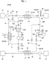
- Fig. 1 is a schematic configuration diagram schematically showing a configuration of a ship 2A or a floating structure 2B provided with a cold recovery system 1 according to an embodiment of the present disclosure.
- the cold recovery system 1 according to some embodiments is installed in the ship 2A or the floating structure 2B.
- the ship 2A or the floating structure 2B is a structure capable of floating on water.
- the ship 2A or the floating structure 2B has a liquefied gas storage device (for example, liquefied gas tank) 21 configured to store a liquefied gas and the cold recovery system 1.
- a liquefied gas storage device for example, liquefied gas tank
- the ship 2A or the floating structure 2B is a structure configured to have a propulsion unit (not shown), such as a propeller, and a propulsion device (not shown) configured to drive the propulsion unit and to drive the propulsion device to be self-propelled.
- a propulsion unit such as a propeller
- a propulsion device not shown
- the present disclosure is also applicable to a case where the ship 2A or the floating structure 2B is a non-self-propelled structure that does not have a propulsion device for self-propelled.
- the cold recovery system 1 is provided with a first heat exchanger 11, a liquefied gas supply line 12 for supplying the liquefied gas from a liquefied gas storage device 21 to a first heat exchanger 11, a vaporized gas supply line 13 for supplying a vaporized gas generated by the vaporization of the liquefied gas in the first heat exchanger 11, a cold recovery cycle 3 configured to circulate a heat medium for cold heat exchanged with the liquefied gas in the first heat exchanger 11, a second heat exchanger 14, and a gas-liquid separator 5.
- the cold recovery cycle 3 is configured to circulate the heat medium for cold under an organic Rankin cycle.
- an upstream side in a circulation direction of the heat medium for cold in the cold recovery cycle 3 may be simply referred to as an upstream side
- a downstream side in the circulation direction may be simply referred to as a downstream side.
- the cold recovery cycle 3 includes a pump for cold 31 to send the heat medium for cold and a turbine for cold 32 configured to be driven by the heat medium for cold.
- the pump for cold 31 is provided on a downstream side of the first heat exchanger 11 and an upstream side of the second heat exchanger 14 in the cold recovery cycle 3.
- the turbine for cold 32 is provided on an upstream side of the first heat exchanger 11 and a downstream side of the second heat exchanger 14 in the cold recovery cycle 3.
- a liquefied natural gas as a specific example of the liquefied gas supplied from the liquefied gas storage device 21, which is a supply source of the liquefied gas, will be described with propane as a specific example of the heat medium for cold circulating in the cold recovery cycle 3 as an example.
- propane a specific example of the heat medium for cold circulating in the cold recovery cycle 3
- propane a specific example of the heat medium for cold circulating in the cold recovery cycle 3
- propane a liquefied natural gas
- propane liquefied petroleum gas, liquid hydrogen, or the like
- the present disclosure is also applicable to a case where a heat medium other than propane (for example, an organic medium) is used as the heat medium for cold that flows in the cold recovery cycle 3.
- propane for example, an organic medium
- the heat medium for cold has a boiling point and a freezing point lower than that of water.
- the first heat exchanger (liquefied gas vaporizer, cold-side condenser) 11 is configured to exchange heat between the liquefied gas sent from the liquefied gas supply line 12 and the heat medium for cold flowing on a downstream side of the turbine for cold 32 and an upstream side of the pump for cold 31 in the cold recovery cycle 3.
- the first heat exchanger 11 includes a first liquefied-gas-side flow path 111 through which the liquefied gas sent from the liquefied gas supply line 12 flows and a first cold-side flow path 112 through which the heat medium for cold circulating in the cold recovery cycle 3 flows.
- a temperature of the liquefied gas flowing through the first liquefied-gas-side flow path 111 is lower than that of the heat medium for cold flowing through the first cold-side flow path 112.
- the first heat exchanger 11 With the heat exchange between the liquefied gas flowing through the first liquefied-gas-side flow path 111 and the heat medium for cold flowing through the first cold-side flow path 112, cold energy of the liquefied gas flowing through the first liquefied-gas-side flow path 111 is transferred to the heat medium for cold flowing through the first cold-side flow path 112. Accordingly, the liquefied gas flowing through the first liquefied-gas-side flow path 111 is heated and vaporized, and the heat medium for cold flowing through the first cold-side flow path 112 is cooled and condensed.
- the second heat exchanger (cold-side evaporator) 14 is configured to exchange heat between external water (heat medium) introduced from the outside of the cold recovery system 1 and the heat medium for cold flowing on a downstream side of the pump for cold 31 and an upstream side of the turbine for cold 32 in the cold recovery cycle 3.
- the second heat exchanger 14 includes a second cold-side flow path 141 through which the heat medium for cold flows and a heat-medium-side flow path 142 through which the external water flows.
- the second cold-side flow path 141 (second heat exchanger 14) is provided on the downstream side of the pump for cold 31 and the upstream side of the turbine for cold 32 in the cold recovery cycle 3.
- a temperature of the external water flowing through the heat-medium-side flow path 142 is higher than that of the heat medium for cold flowing through the second cold-side flow path 141.
- the heat exchanger 14 With the heat exchange between the heat medium for cold flowing through the second cold-side flow path 141 and the external water flowing through the heat-medium-side flow path 142, heat energy of the external water flowing through the heat-medium-side flow path 142 is transferred to the heat medium for cold flowing through the second cold-side flow path 141. Accordingly, the heat medium for cold flowing through the second cold-side flow path 141 is heated and vaporized.
- One side (upstream end) of the liquefied gas supply line 12 is connected to the liquefied gas storage device 21, and the other side (downstream end) of the liquefied gas supply line 12 is connected to an upstream end (gas inlet of the first heat exchanger 11) of the first liquefied-gas-side flow path 111.
- One side (upstream end) of the vaporized gas supply line 13 is connected to a downstream end (gas outlet of the first heat exchanger 11) of the first liquefied-gas-side flow path 111, and the other side (downstream end) of the vaporized gas supply line 13 is connected to a vaporized gas supply destination 22.
- the vaporized gas supply destination 22 may be a facility provided outside the ship 2A or the floating structure 2B (for example, power generation facility or gas storage facility on land) or may be a facility mounted on the ship 2A or the floating structure 2B.
- the cold recovery system 1 is further provided with a pump for liquefied gas 15 provided in the liquefied gas supply line 12.
- the pump for liquefied gas 15 has a rotor blade (not shown) provided in the liquefied gas supply line 12 and is configured to rotate this rotor blade by electric power or the like supplied to the pump for liquefied gas 15 to send the liquefied gas to a downstream side (side where the first heat exchanger 11 is located) of the liquefied gas supply line 12.
- the liquefied gas stored in the liquefied gas storage device 21 is extracted to the liquefied gas supply line 12 and is sent to the first liquefied-gas-side flow path 111 of the first heat exchanger 11 through the liquefied gas supply line 12.
- the vaporized gas generated by the vaporization of the liquefied gas in the first liquefied-gas-side flow path 111 of the first heat exchanger 11 is sent to the gas supply destination 22 through the vaporized gas supply line 13 by the pump for liquefied gas 15.
- the cold recovery system 1 is further provided with an external water supply line 42 for supplying the external water from an external water supply source 41 to a heat exchanger (second heat exchanger 14) using the external water of the cold recovery system 1 as a heat medium, an external water discharge line 44 for discharging the external water discharged from the heat exchanger using the external water as the heat medium to an external water discharge destination 43, and a pump for external water 45 provided in the external water supply line 42.
- an external water supply line 42 for supplying the external water from an external water supply source 41 to a heat exchanger (second heat exchanger 14) using the external water of the cold recovery system 1 as a heat medium
- an external water discharge line 44 for discharging the external water discharged from the heat exchanger using the external water as the heat medium to an external water discharge destination 43
- a pump for external water 45 provided in the external water supply line 42.
- One side (upstream end) of the external water supply line 42 is connected to the external water supply source 41, and the other side (downstream end) of the external water supply line 42 is connected to an upstream end (heat medium inlet of the second heat exchanger 14) of the heat-medium-side flow path 142.
- One side (upstream end) of the external water discharge line 44 is connected to a downstream end (heat medium outlet of the second heat exchanger 14) of the heat-medium-side flow path 142, and the other side (downstream end) of the external water discharge line 44 is connected to the external water discharge destination 43.
- the external water may be any water that can heat a heat exchange target as a heat medium in the heat exchanger (water having a temperature higher than that of the heat exchange target) and may be water at room temperature.
- water for example, outboard water such as seawater or engine cooling water obtained by cooling engine of ship 2A) that is easily available in the ship 2A or the floating structure 2B is preferable.
- the external water supply source 41 may be an intake port provided in the ship 2A or the floating structure 2B to take in the external water (for example, seawater) from the outside of the ship 2A or the floating structure 2B, or may be a facility (for example, water storage tank) provided inside the ship 2A or the floating structure 2B.
- the external water discharge destination 43 may be a drain port provided in the ship 2A or the floating structure 2B for discharging the external water to the outside of the ship 2A or the floating structure 2B, or may be a facility (for example, wastewater tank) provided inside the ship 2A or the floating structure 2B.
- the pump for external water 45 has a rotor blade (not shown) provided in the external water supply line 42 and is configured to rotate this rotor blade by electric power or the like supplied to the pump for external water 45 to send the external water to a downstream side (side where the second heat exchanger 14 is located) of the external water supply line 42.
- a rotor blade not shown
- electric power or the like supplied to the pump for external water 45 to send the external water to a downstream side (side where the second heat exchanger 14 is located) of the external water supply line 42.
- the cold recovery cycle 3 further includes a first connection line 33 and a second connection line 34.
- the first connection line 33 connects a downstream end (outlet of the heat medium for cold of the first heat exchanger 11) of the first cold-side flow path 112 and an upstream end (inlet of the heat medium for cold of the second heat exchanger 14) of the second cold-side flow path 141.
- the pump for cold 31 described above is provided in the first connection line 33.
- the second connection line 34 connects a downstream end (outlet of the heat medium for cold of the second heat exchanger 14) of the second cold-side flow path 141 and an upstream end (inlet of the heat medium for cold of the first heat exchanger 11) of the first cold-side flow path 112.
- the turbine for cold 32 described above is provided in the second connection line 34.
- the gas-liquid separator 5 is configured to separate the heat medium for cold into a gas phase and a liquid phase.
- the gas-liquid separator 5 is provided on a downstream side of the first cold-side flow path 112 (the first heat exchanger 11) and on the upstream side of the pump for cold 31 in the cold recovery cycle 3. Specifically, the gas-liquid separator 5 is provided on the upstream side of the pump for cold 31 in the first connection line 33.
- the gas-liquid separator 5 includes a main body portion 52 configured to internally define an internal space 51 into which the heat medium for cold, which has been sent from the first cold-side flow path 112 (the first heat exchanger 11), is introduced through the first connection line 33, an introduction inlet 53 for introducing the heat medium for cold into the internal space 51, and a liquid-phase discharge port 54 for discharging a liquid-phase heat medium for cold to the outside of the gas-liquid separator 5 from the internal space 51.
- the internal space 51 includes a lower-side storage space 51B in which the liquid-phase heat medium for cold is stored and an upper-side storage space 51A, which is provided to communicate with the lower-side storage space 51B above the lower-side storage space 51B, in which a gas-phase heat medium for cold is stored.
- the liquid-phase discharge port 54 communicates with the lower-side storage space 51B.
- the first connection line 33 described above includes a first upper-stage connection line 33A connecting the downstream end of the first cold-side flow path 112 and the introduction inlet 53, a first middle-stage connection line 33B connecting the liquid-phase discharge port 54 and a pump inlet 311 of the pump for cold 31, and a first lower-stage connection line 33C connecting a pump outlet 312 of the pump for cold 31 and the upstream end of the second cold-side flow path 141.
- the heat medium for cold cooled by the first heat exchanger 11 is guided to the gas-liquid separator 5 through the first upper-stage connection line 33A.
- the heat medium for cold that has flowed into the internal space 51 from the introduction inlet 53 is separated into a liquid phase and a gas phase in the internal space 51.
- the pump for cold 31 is configured to send the heat medium for cold to the downstream side (side where the second heat exchanger 14 is located) of the cold recovery cycle 3.
- the pump for cold 31 has a rotor blade (not shown) provided in the first connection line 33 and is configured to rotate this rotor blade by electric power or the like supplied to the pump for cold 31 to send the liquid-phase heat medium for cold to a downstream side of the first connection line 33.
- the liquid-phase heat medium for cold stored in the lower-side storage space 51B is guided to the pump for cold 31 through the liquid-phase discharge port 54 and the first middle-stage connection line 33B to be pressurized by the pump for cold 31.
- the liquid-phase heat medium for cold pressurized by the pump for cold 31 is sent to the second cold-side flow path 141 (second heat exchanger 14) through the first lower-stage connection line 33C by the pump for cold 31.
- the cold recovery system 1 is further provided with a liquid return line 6 for returning the liquid-phase heat medium for cold to the gas-liquid separator 5 from the downstream side of the pump for cold 31 and the upstream side of the second heat exchanger 14 in the cold recovery cycle 3 and a first flow regulation valve 35 provided between a connecting portion P1 with an upstream end of the liquid return line 6 and the second heat exchanger 14 in the cold recovery cycle 3.
- the first flow regulation valve 35 is configured to regulate a flow rate of the liquid-phase heat medium for cold guided to the second heat exchanger 14.
- the gas-liquid separator 5 further includes a liquid return port 55 for introducing the liquid-phase heat medium for cold from the liquid return line 6 into the internal space 51.
- the liquid return port 55 communicates with the internal space 51.
- One side (upstream end) of the liquid return line 6 is connected to the connecting portion P1 of the first lower-stage connection line 33C, and the other side (downstream end) of the liquid return line 6 is connected to the liquid return port 55.
- the first flow regulation valve 35 is provided on a downstream side of the connecting portion P1 of the first lower-stage connection line 33C.
- the first flow regulation valve 35 moves a valve body (not shown) that opens and closes a flow path of the heat medium for cold to be able to regulate the flow rate of the heat medium for cold to be supplied to a downstream side (second heat exchanger 14 side) of the valve body.
- the first flow regulation valve 35 may be an opening-closing valve whose opening degree can be regulated to be fully closed and fully open, or may be an opening degree regulation valve whose opening degree can be regulated to be fully closed, fully open, and at least one intermediate opening degree between the fully closed and fully open.
- the heat medium for cold which is pressurized by the pump for cold 31 and whose temperature is raised by the second heat exchanger 14, is introduced into the turbine for cold 32 as a working fluid.
- the turbine for cold 32 includes a rotary shaft 321, a turbine blade 322 attached to the rotary shaft 321, and a casing 323 that rotatably accommodates the turbine blade 322.
- An introduction inlet 324 for introducing the heat medium for cold into the inside of the casing 323 and a discharge port 325 for discharging the heat medium for cold that has passed through the turbine blade 322 to the outside of the casing 323 are formed in the casing 323.
- the turbine for cold 32 is configured to rotate the turbine blade 322 by energy of the heat medium for cold introduced into the inside of the casing 323 through the introduction inlet 324.
- the heat medium for cold that has passed through the turbine blade 322 is discharged to the outside of the casing 323 through the discharge port 325.
- the cold recovery cycle 3 is configured to recover a rotational force generated by the turbine blade 322 as power.
- the cold recovery cycle 3 further includes a generator for cold 326 configured to generate power with drive of the turbine for cold 32.
- the generator for cold 326 is mechanically connected to the rotary shaft 321 and is configured to convert the rotational force of the turbine blade 322 into electric power.
- the cold recovery cycle 3 may not convert the rotational force generated by the turbine blade 322 into electric power and may recover the rotational force as it is, as power, by a power transmission device (for example, coupling, belt, pulley, or the like).
- the second connection line 34 described above includes a second upper-stage connection line 34A connecting the downstream end of the second cold-side flow path 141 and the introduction inlet 324 of the turbine for cold 32, and a second lower-stage connection line 34B connecting the discharge port 325 of the turbine for cold 32 and the upstream end of the first cold-side flow path 112.
- the cold recovery cycle 3 further includes a turbine bypass line 36 connecting the upstream side and the downstream side of the turbine for cold 32 of the second connection line 34 by bypassing the turbine for cold 32, a turbine-side flow regulation valve 37, and a turbine-bypass-side flow regulation valve 38.
- One side (upstream end) of the turbine bypass line 36 is connected to a branching portion P2 of the second upper-stage connection line 34A, and the other side (downstream end) of the turbine bypass line 36 is connected to a merging portion P3 of the second lower-stage connection line 34B.
- the turbine-side flow regulation valve 37 is provided on a downstream side (turbine for cold 32 side) of the branching portion P2 of the second upper-stage connection line 34A.
- the turbine-bypass-side flow regulation valve 38 is provided in the turbine bypass line 36.
- Each of the turbine-side flow regulation valve 37 and the turbine-bypass-side flow regulation valve 38 moves a valve body (not shown) that opens and closes the flow path of the heat medium for cold to be able to regulate the flow rate of the heat medium for cold to be supplied to a downstream side of the valve body.
- Each of the turbine-side flow regulation valve 37 and the turbine-bypass-side flow regulation valve 38 may be an opening-closing valve whose opening degree can be regulated to be fully closed or fully open, or may be an opening degree regulation valve whose opening degree can be regulated to be fully closed, fully open, and at least one intermediate opening degree between the fully closed and fully open.
- the cold recovery system 1 is further provided with a third heat exchanger 7 configured to transfer the cold energy of the liquefied gas extracted from the liquefied gas storage device 21 to any one of the liquid-phase heat medium for cold that is returned to the gas-liquid separator 5 via the liquid return line 6 or the heat mediums for cold that is present inside the gas-liquid separator 5.
- the third heat exchanger (precooler) 7 is configured to exchange heat between the liquefied gas extracted from the liquefied gas storage device 21 and the heat medium for cold circulating via the gas-liquid separator 5 or the liquid return line 6.
- the third heat exchanger 7 (7A) includes a third cold-side flow path 71 through which the heat medium for cold provided in the liquid return line 6 flows and a second liquefied-gas-side flow path 72 through which the liquefied gas flows.
- the heat medium for cold flowing through the third cold-side flow path 71 has a higher temperature than that of the liquefied gas flowing through the second liquefied-gas-side flow path 72.
- the third heat exchanger 7 (7A) With the heat exchange between the heat medium for cold flowing through the third cold-side flow path 71 and the liquefied gas flowing through the second liquefied-gas-side flow path 72, cold energy of the liquefied gas flowing through the second liquefied-gas-side flow path 72 is transferred to the heat medium for cold flowing through the third cold-side flow path 71. Accordingly, the heat medium for cold flowing through the third cold-side flow path 71 is cooled.
- the cold recovery system 1 is further provided with a liquefied gas introduction line 81 for guiding the liquefied gas from the liquefied gas storage device 21 to the third heat exchanger 7 and a gas discharge line 82 for guiding the vaporized gas in which the liquefied gas is vaporized from the third heat exchanger 7.
- one side (upstream end) of the liquefied gas introduction line 81 is connected to a connection position P4 on a downstream side of the pump for liquefied gas 15 of the liquefied gas supply line 12.
- the other side (downstream end) of the liquefied gas introduction line 81 is connected to an upstream end (gas inlet of the third heat exchanger 7) of the second liquefied-gas-side flow path 72.
- One side (upstream end) of the gas discharge line 82 (82A) is connected to a downstream end (gas outlet of the third heat exchanger 7) of the second liquefied-gas-side flow path 72.
- the other side (downstream end) of the gas discharge line 82 (82A) is connected to a connection position P5 of the vaporized gas supply line 13.
- the liquefied gas stored in the liquefied gas storage device 21 is extracted to the liquefied gas supply line 12 and is sent to a portion on an upstream side of the connection position P4 of the liquefied gas supply line 12 and the second liquefied-gas-side flow path 72 of the third heat exchanger 7 through the liquefied gas introduction line 81.
- the vaporized gas generated by the vaporization of the liquefied gas in the second liquefied-gas-side flow path 72 of the third heat exchanger 7 is sent, by the pump for liquefied gas 15, to the gas supply destination 22 through the gas discharge line 82 (82A) and a portion on a downstream side of the connection position P5 of the vaporized gas supply line 13.
- the cold recovery system 1 is further provided with a second flow regulation valve 83, a third flow regulation valve 84, a fourth flow regulation valve 85, and a fifth flow regulation valve 86.
- the second flow regulation valve 83 is an opening degree regulation valve whose opening degree can be regulated to be fully closed, fully open, and at least one intermediate opening degree between the fully closed and fully open.
- Each of the flow regulation valves 84, 85, and 86 may be an opening-closing valve whose opening degree can be regulated to be fully closed and fully open, or may be an opening degree regulation valve whose opening degree can be regulated to be fully closed, fully open, and at least one intermediate opening degree between the fully closed and fully open.
- the second flow regulation valve 83 is provided in the liquefied gas introduction line 81 and is configured to regulate the flow rate of the liquefied gas guided to the third heat exchanger 7.
- the third flow regulation valve 84 is provided on a downstream side of the connection position P4 of the liquefied gas supply line 12 and is configured to regulate the flow rate of the liquefied gas guided to the first heat exchanger 11. With opening (full opening or intermediate opening degree) of the second flow regulation valve 83 and full closing of the third flow regulation valve 84, it is possible to send the liquefied gas to the third heat exchanger 7 from the liquefied gas storage device 21 by the pump for liquefied gas 15.
- the fourth flow regulation valve 85 is provided on an upstream side of the connection position P5 of the vaporized gas supply line 13 and is configured to regulate the flow rate of the vaporized gas guided to the gas supply destination 22.
- the fifth flow regulation valve 86 is provided in the gas discharge line 82 and is configured to regulate the flow rate of the vaporized gas guided to the gas supply destination 22. With opening (full opening or intermediate opening degree) of the fourth flow regulation valve 85 and full closing of the fifth flow regulation valve 86, it is possible to send the heat medium for cold to the gas supply destination 22 from the first heat exchanger 11 by the pump for liquefied gas 15.
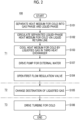
- Fig. 2 is a flowchart of a startup method for the cold recovery system according to an embodiment of the present disclosure.
- Fig. 3 is an explanatory diagram for describing an example of control in the cold recovery system according to an embodiment of the present disclosure.
- a period from the startup of the cold recovery system 1 to a steady operation is classified into a first period (precooling period) T1, a second period (transition period) T2, and a third period T3 (cold recovery period).
- the second period T2 is a period after the first period T1 and is a period before the third period T3.
- the liquefied gas extracted from the liquefied gas storage device 21 is sent to the third heat exchanger 7.
- the liquefied gas extracted from the liquefied gas storage device 21 is sent to the first heat exchanger 11.
- a destination of the liquefied gas extracted from the liquefied gas storage device 21 is changed from the third heat exchanger 7 to the first heat exchanger 11.
- a startup method 100 of the cold recovery system 1 is provided with a gas-liquid separation step S101, a circulation step S102, and a cooling step S103.
- the gas-liquid separator 5 described above separates the heat medium for cold into a gas phase and a liquid phase.
- the gas-liquid separation step S101 is continuously performed during the period from the startup of the cold recovery system 1 to the steady operation and during the steady operation.
- the heat medium for cold may be vaporized in the cold recovery cycle 3 due to heat input from the ambient air to the cold recovery cycle 3 or the gas-liquid separator 5 when the cold recovery system 1 is stopped. For this reason, at the time of startup of the cold recovery system 1, a ratio of the gas-phase heat medium for cold is large on the downstream side of the first heat exchanger 11 in the cold recovery cycle 3, such as the gas-liquid separator 5 or the pump for cold 31, and in the second heat exchanger 14, as compared with the steady operation of the cold recovery system 1. When the ratio of the gas-phase heat medium for cold in the pump for cold 31 is large, the capacity of the pump for cold 31 may be decreased due to gas entrainment.
- the pump for cold 31 is driven to return the liquid-phase heat medium for cold separated in the gas-liquid separation step S101 to the gas-liquid separator 5 via the liquid return line 6. Accordingly, the liquid-phase heat medium for cold circulates through the gas-liquid separator 5, the pump for cold 31, and the liquid return line 6.
- the circulation step S102 is started in the first period T1 and continuously performed until the second period T2.
- the pump for cold 31 is driven in a state where the first flow regulation valve 35 is fully closed to extract the liquid-phase heat medium for cold from the gas-liquid separator 5 via the liquid-phase discharge port 54.
- the liquid-phase heat medium for cold extracted from the gas-liquid separator 5 passes through the first middle-stage connection line 33B, the pump for cold 31, an upstream side of the connecting portion P1 of the first lower-stage connection line 33C, and the liquid return line 6, and then sent to the gas-liquid separator 5 by the pump for cold 31.
- the cold energy of the liquefied gas extracted from the liquefied gas storage device 21 is transferred, for cooling, to any one of the liquid-phase heat medium for cold returned to the gas-liquid separator 5 via the liquid return line 6 in the circulation step S102 or the heat medium for cold inside the gas-liquid separator 5.
- the cooling step S103 the liquefied gas is sent from the liquefied gas storage device 21 to the third heat exchanger 7, and the heat medium for cold is cooled by the liquefied gas in the third heat exchanger 7. Accordingly, the liquid-phase heat medium for cold, which circulates through the gas-liquid separator 5, the pump for cold 31, and the liquid return line 6, is cooled.
- the cooling step S103 is started after the circulation step S102 in the first period T1. As shown in Fig. 3 , the pump for liquefied gas 15 is driven after the pump for cold 31 is driven.
- the pump for liquefied gas 15 is driven in a state where the second flow regulation valve 83 or the fifth flow regulation valve 86 is open (fully open or intermediate opening degree) and the third flow regulation valve 84 or the fourth flow regulation valve 85 is fully closed. Accordingly, it is possible to send the liquefied gas from the liquefied gas storage device 21 to the third heat exchanger 7 and to send the vaporized gas from the third heat exchanger 7 to the gas supply destination 22.
- the cooling step S103 With the cooling of the liquid-phase heat medium for cold circulating through the gas-liquid separator 5, the pump for cold 31, and the liquid return line 6, a temperature inside the gas-liquid separator 5 can be lowered. Therefore, it is possible to condense the gas-phase heat medium for cold inside the gas-liquid separator 5. Accordingly, it is possible to increase the ratio of the liquid-phase heat medium for cold at an early stage on the downstream side of the first heat exchanger 11 in the cold recovery cycle 3, such as the gas-liquid separator 5 or the pump for cold 31, and the upstream side of the second heat exchanger 14. With the increase in the ratio of the liquid-phase heat medium for cold in the pump for cold 31, it is possible to suppress the decrease in the capacity of the pump for cold 31 due to gas entrainment and thus to exert the capacity of the pump for cold 31 from an early stage.
- the startup method 100 of the cold recovery system 1 is further provided with a valve opening step S104 of opening (changing from full closing to full opening or intermediate opening degree) the first flow regulation valve 35 after the start of the cooling step S103 to send the heat medium for cold to the first heat exchanger 11 by the pump for cold 31, a change step S105 of changing the destination of the liquefied gas extracted from the liquefied gas storage device 21 to the first heat exchanger 11 from the third heat exchanger 7 after the valve opening step S104, a turbine for cold drive step S106 of guiding the heat medium for cold to the turbine for cold 32 after the change step S105 to drive the turbine for cold 32, and a pump for external water drive step S107 of driving the pump for external water 45 before the valve opening step S104.
- a valve opening step S104 of opening (changing from full closing to full opening or intermediate opening degree) the first flow regulation valve 35 after the start of the cooling step S103 to send the heat medium for cold to the first heat exchanger 11 by the pump for cold 31
- a change step S105 of changing
- the valve opening step S104 is performed, for example, when the temperature inside the gas-liquid separator 5 becomes equal to or lower than a predetermined temperature (temperature at which the heat medium for cold condenses).
- a predetermined temperature temperature at which the heat medium for cold condenses.
- the second flow regulation valve 83 is regulated to maintain the temperature inside the gas-liquid separator 5 within a predetermined range with the predetermined temperature as an upper limit.
- the liquid-phase heat medium for cold that has passed through the first flow regulation valve 35 is heated by the second heat exchanger 14, vaporized, and then sent to the first heat exchanger 11.
- the liquid-phase heat medium for cold that has passed through the first flow regulation valve 35 passes through a downstream side of the first flow regulation valve 35 of the first lower-stage connection line 33C, the second cold-side flow path 141 (second heat exchanger 14), an upstream side of the branching portion P2 of the second upper-stage connection line 34A, and a downstream side of the merging portion P3 of the turbine bypass line 36 and the second lower-stage connection line 34B, and is sent to the first cold-side flow path 112 (first heat exchanger 11).
- first heat exchanger 11 first heat exchanger 11
- the pump for external water 45 is driven before the valve opening step S104 (S107), and the external water is supplied to the heat-medium-side flow path 142 of the second heat exchanger 14.
- the liquid-phase heat medium for cold that has passed through the first flow regulation valve 35 is heated, for vaporization, by the second heat exchanger 14 with the external water (heat medium).
- the heat exchange between the liquefied gas and the heat medium for cold is not performed in the first heat exchanger 11.
- the gas-phase heat medium for cold that has passed through the first heat exchanger 11 is condensed in the gas-liquid separator 5 whose inside is cooled by the third heat exchanger 7.
- valve opening step S104 with regulation of an opening degree of the first flow regulation valve 35, it is possible to stabilize an amount of the liquid-phase heat medium for cold inside the gas-liquid separator 5.
- the destination of the liquefied gas extracted from the liquefied gas storage device 21 is changed from the third heat exchanger 7 to the first heat exchanger 11.
- the turbine for cold drive step S106 is performed during the third period T3 described above. That is, the turbine for cold drive step S106 is performed after the change step S105.
- the change step S105 is performed, for example, when the flow rate (amount of the liquid-phase heat medium for cold stored in the lower-side storage space 51B) of the heat medium for cold that can be sent to the first heat exchanger 11 by the pump for cold 31 with the circulation of the liquid-phase heat medium for cold by the pump for cold 31 is equal to or larger than a certain amount.
- the second flow regulation valve 83 or the fifth flow regulation valve 86 is closed (changed from full opening or intermediate opening degree to full closing), and the third flow regulation valve 84 or the fourth flow regulation valve 85 is open (changed from full closing to full opening or intermediate opening degree) .
- the turbine-side flow regulation valve 37 is open (changed from full closing to full opening or intermediate opening degree), and the turbine-bypass-side flow regulation valve 38 is closed (changed from full opening or intermediate opening degree to full closing). Accordingly, the heat medium for cold, which is pressurized by the pump for cold 31 and whose temperature is raised by the second heat exchanger 14, is introduced into the turbine for cold 32, and the turbine blade 322 of the turbine for cold 32 rotate to drive the turbine for cold 32.
- the cooling step S103 with the cooling of the liquid-phase heat medium for cold circulating through the gas-liquid separator 5, the pump for cold 31, and the liquid return line 6 by the liquefied gas in the third heat exchanger 7 (cooling step S103), it is possible to increase the ratio of the liquid-phase heat medium for cold at an early stage on the downstream side of the first heat exchanger 11 in the cold recovery cycle 3, such as the gas-liquid separator 5 or the pump for cold 31.
- the increase in the ratio of the liquid-phase heat medium for cold in the pump for cold 31 it is possible to suppress the decrease in the capacity of the pump for cold 31 due to gas entrainment and thus to exert the capacity of the pump for cold 31 from an early stage. Accordingly, it is possible to shift the cold recovery system 1 to the steady operation at an early stage.
- the heat exchange in the first heat exchanger 11 is not performed until the flow rate of the heat medium for cold supplied to the first heat exchanger 11 becomes a large flow rate that does not cause the first heat exchanger 11 to be blocked, and thus it is possible to suppress the blockage of the first heat exchanger 11 at the time of startup of the cold recovery system 1.
- the cold recovery system 1 is provided with the first heat exchanger 11 described above, the second heat exchanger 14 described above, the cold recovery cycle 3 described above, the gas-liquid separator 5 described above, the liquid return line 6 described above, and the third heat exchanger 7 described above.
- the heat exchange in the first heat exchanger 11 is not performed until the flow rate of the heat medium for cold supplied to the first heat exchanger 11 becomes a large flow rate that does not cause the first heat exchanger 11 to be blocked, and thus it is possible to suppress the blockage of the first heat exchanger 11 at the time of startup of the cold recovery system 1.
- the cold recovery system 1 described above is provided with the first flow regulation valve 35 described above.
- the first flow regulation valve 35 it is possible to form a closed circuit including the gas-liquid separator 5, the pump for cold 31, and the liquid return line 6 with the closing of the first flow regulation valve 35.
- the third heat exchanger 7 (7A) described above is configured to transfer the cold energy of the liquefied gas extracted from the liquefied gas storage device 21 to the liquid-phase heat medium for cold flowing through the liquid return line 6.
- the third heat exchanger 7 (7A) can cool the heat medium for cold flowing through the liquid return line 6 by the liquefied gas. Therefore, it is possible to quickly lower the temperature inside the gas-liquid separator 5 to the predetermined temperature or lower. Accordingly, it is possible to shift the cold recovery system 1 to the steady operation at an early stage.
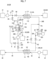
- FIG. 4 to 8 is a schematic configuration diagram schematically showing a configuration of a ship or a floating structure provided with a cold recovery system according to an embodiment of the present disclosure.
- the liquid return line 6 described above includes a first liquid return line 6A provided with the third heat exchanger 7 and a second liquid return line 6B that bypasses the third heat exchanger 7.
- one side (upstream end) of the first liquid return line 6A is connected to the connecting portion P1 of the first lower-stage connection line 33C, and the other side (downstream end) thereof is connected to the liquid return port 55.
- One side (upstream end) of the second liquid return line 6B is connected to a branching portion P6 located on an upstream side of the third heat exchanger 7 of the first liquid return line 6A, and the other side (downstream end) thereof is connected to a merging portion P7 located on a downstream side of the third heat exchanger 7 of the first liquid return line 6A.
- the liquid return line 6 described above may further include a first opening-closing valve 61 provided between the branching portion P6 of the first liquid return line 6A and the third heat exchanger 7 and a second opening-closing valve 62 provided in the second liquid return line 6B.
- a first opening-closing valve 61 provided between the branching portion P6 of the first liquid return line 6A and the third heat exchanger 7
- a second opening-closing valve 62 provided in the second liquid return line 6B.
- the pump for cold 31 is rotated at a steady rotation speed. Even after the valve opening step S104 is executed, the heat medium for cold is circulated through the liquid return line 6.
- the third heat exchanger 7 (7B) is configured to transfer the cold energy of the liquefied gas extracted from the liquefied gas storage device 21 to the heat medium for cold inside the gas-liquid separator 5.
- the third heat exchanger 7 (7B) includes a third liquefied-gas-side flow path 73 through which the liquefied gas disposed in the internal space 51 of the gas-liquid separator 5 flows.
- the third liquefied-gas-side flow path 73 may be a pipeline through which the liquefied gas can flow and a pipeline whose outer surface faces the internal space 51.
- the other side (downstream end) of the liquefied gas introduction line 81 is connected to an upstream end (gas inlet of the third heat exchanger 7) of the third liquefied-gas-side flow path 73.
- One side (upstream end) of the gas discharge line 82 is connected to a downstream end (gas outlet of the third heat exchanger 7) of the third liquefied-gas-side flow path 73.
- the heat medium for cold in the internal space 51 has a higher temperature than that of the liquefied gas flowing through the third liquefied-gas-side flow path 73.
- the heat exchanger 7 (7B) With the heat exchange between the heat medium for cold in the internal space 51 and the liquefied gas flowing through the third liquefied-gas-side flow path 73, cold energy of the liquefied gas flowing through the third liquefied-gas-side flow path 73 is transferred to the heat medium for cold in the internal space 51. Accordingly, the heat medium for cold in the internal space 51 is cooled.
- the third heat exchanger 7 (7B) can cool the heat medium for cold inside the gas-liquid separator 5 by the liquefied gas. Therefore, it is possible to quickly lower the temperature inside the gas-liquid separator 5 to the predetermined temperature or lower. Accordingly, it is possible to shift the cold recovery system 1 to the steady operation at an early stage.
- the gas supply destination 22 described above includes a main engine 22A of the ship 2A or the floating structure 2B.
- the main engine 22A is configured to generate a driving force (thrust) for driving a propulsion unit (not shown) such as a propeller by using energy of the supplied vaporized gas.
- the vaporized gas supply line 13 described above includes a fuel supply line 13A for supplying the liquefied gas vaporized by the first heat exchanger 11 to the main engine 22A of the ship 2A or the floating structure 2B.
- the gas discharge line 82 (82A) described above includes a flow path for guiding the vaporized gas obtained by vaporizing the liquefied gas from the third heat exchanger 7 to the main engine 22A.
- the vaporized gas that has passed through the third heat exchanger 7 is guided to the main engine 22A via the gas discharge line 82 (82A) or the like.
- the gas discharge line 82 includes a startup gas supply line 82B for guiding the vaporized gas obtained by vaporizing the liquefied gas from the third heat exchanger 7 to a gas combustion device 23 configured separately from the main engine 22A.
- the gas combustion device 23 is configured to combust the supplied gas.
- One side (downstream end) of the startup gas supply line 82B is connected to a gas inlet of the gas combustion device 23.
- the other side (upstream end) of the startup gas supply line 82B is connected to the downstream end (gas outlet of the third heat exchanger 7) of the second liquefied-gas-side flow path 72.
- the other side (upstream end) of the startup gas supply line 82B is connected to the downstream end (gas outlet of the third heat exchanger 7) of the third liquefied-gas-side flow path 73.
- the flow rate of the heat medium for cold circulating in the cold recovery cycle 3 is small at the time of startup of the cold recovery system 1.
- the liquefied gas is supplied to the main engine 22A without being sufficiently vaporized and a failure or malfunction of the main engine 22A may occur.
- the vaporized gas or the liquefied gas can be combusted in the gas combustion device 23 by being guided to the gas combustion device 23 via the startup gas supply line 82B. Accordingly, the supply of the liquefied gas to the main engine 22A without being sufficiently vaporized can be suppressed, and thus it is possible to suppress a failure or malfunction of the main engine 22A.
- the cold recovery system 1 described above may be configured to not perform the heat exchange between the heat medium for cold and the external water in the second heat exchanger 14 when the pump for external water 45 is in a drive state.
- the cold recovery system 1 is further provided with a heat-exchanger-side bypass line 46 that connects the external water supply line 42 and the external water discharge line 44 by bypassing the second heat exchanger 14.
- One side (upstream end) of the heat-exchanger-side bypass line 46 is connected to a branching portion P8 of the external water supply line 42.
- the other side (downstream end) of the heat-exchanger-side bypass line 46 is connected to a merging portion P9 of the external water discharge line 44.
- the cold recovery system 1 described above may be further provided with a first external-water-side opening-closing valve 47 provided on a downstream side of the branching portion P8 of the external water supply line 42 and a second external-water-side opening-closing valve 48 provided in the heat-exchanger-side bypass line 46.
- a first external-water-side opening-closing valve 47 provided on a downstream side of the branching portion P8 of the external water supply line 42
- a second external-water-side opening-closing valve 48 provided in the heat-exchanger-side bypass line 46.
- a period until the pump for external water 45 transits to a steady state is required from the start of driving the pump for external water 45, and the flow rate of the external water supplied to the second heat exchanger 14 is not stable during this period.
- the external water is caused to pass through the heat-exchanger-side bypass line 46 during the period until the pump for external water 45 transits to the steady state, and thus a stable operation becomes possible when the cold recovery system 1 transits to the steady operation.
- the external water may be caused to pass through the heat-exchanger-side bypass line 46 for a predetermined period from the start of the pump for external water drive step S107.
- the valve opening step S104 may be started during the predetermined period.
- the cold recovery system 1 may be provided with, instead of the heat-exchanger-side bypass line 46, a bypass line that connects a portion on the downstream side of the connecting portion P1 of the first lower-stage connection line 33C and a portion on the upstream side of the branching portion P2 of the second upper-stage connection line 34A by bypassing the second heat exchanger 14.
- Fig. 9 is an explanatory diagram for describing a control device for a cold recovery system according to an embodiment of the present disclosure.
- the cold recovery system 1 is further provided with a temperature acquisition device (temperature sensor in the illustrated example) 87 configured to acquire the temperature of the heat medium for cold inside the gas-liquid separator 5 and a valve opening degree control device 88 that controls the opening degree of the second flow regulation valve 83 such that the temperature of the heat medium for cold acquired by the temperature acquisition device 87 falls within a predetermined range.
- a temperature acquisition device temperature sensor in the illustrated example
- a valve opening degree control device 88 that controls the opening degree of the second flow regulation valve 83 such that the temperature of the heat medium for cold acquired by the temperature acquisition device 87 falls within a predetermined range.
- the valve opening degree control device 88 is mounted on a control device 9 configured to perform operation control of a pump provided in the cold recovery system 1 and opening degree control of a valve provided in the cold recovery system 1.
- the pump (pump for cold 31 or the like) provided in the cold recovery system 1 is configured to be driven or stopped in accordance with an operation instruction of the control device 9.
- the valve (first flow regulation valve 35 or the like) provided in the cold recovery system 1 is configured to regulate the valve opening degree in accordance with an opening degree instruction of the control device 9.
- the cold recovery system 1 is provided with the control device 9.
- the control device 9 is an electronic control unit that controls the cold recovery system 1.
- the control device 9 is configured as a microcomputer consisting of a CPU (processor) (not shown), a memory such as a ROM or a RAM, a storage device such as an external storage device, an I/O interface, a communication interface, and the like.
- the CPU may operate (for example, data calculation) in accordance with a command of a program loaded in a main storage device of the memory to realize the control in the valve opening degree control device 88.
- the valve opening degree of the second flow regulation valve 83 by the valve opening degree control device 88 and the maintaining of the temperature of the heat medium for cold acquired by the temperature acquisition device 87 within the predetermined range, it is possible to suppress the decrease in the capacity of the pump for cold 31 due to gas entrainment at an early stage and to stabilize the temperature of the heat medium for cold flowing in a circulation cycle or the cold recovery cycle 3 including the gas-liquid separator 5, the pump for cold 31, and the liquid return line 6 at an early stage. Accordingly, since the valve opening step S104, the change step S105, or the like can be executed at an early stage, the cold recovery system 1 can be transferred to the steady operation at an early stage.
- the present disclosure is not limited to the embodiments described above and includes a form in which a modification is added to the embodiments described above or a form in which the above forms are combined as appropriate.
- the heat exchange in the first heat exchanger (11) is not performed until the flow rate of the heat medium for cold supplied to the first heat exchanger (11) becomes a large flow rate that does not cause the first heat exchanger (11) to be blocked, and thus it is possible to suppress the blockage of the first heat exchanger (11) at the time of startup of the cold recovery system (1).
- the cold recovery system (1) according to 1) above, in which the third heat exchanger (7) is configured to transfer the cold energy of the liquefied gas extracted from the liquefied gas storage device (21) to the liquid-phase heat medium for cold flowing through the liquid return line (6) .
- the third heat exchanger (7) can cool the heat medium for cold flowing through the liquid return line (6) by the liquefied gas. Therefore, it is possible to quickly lower the temperature inside the gas-liquid separator (5) to the predetermined temperature or lower. Accordingly, it is possible to shift the cold recovery system (1) to the steady operation at an early stage.
- the cold recovery system (1) according to 1) above, in which the third heat exchanger (7) is configured to transfer the cold energy of the liquefied gas extracted from the liquefied gas storage device (21) to the heat medium for cold inside the gas-liquid separator (5).
- the third heat exchanger (7) can cool the heat medium for cold inside the gas-liquid separator (5) by the liquefied gas. Therefore, it is possible to quickly lower the temperature inside the gas-liquid separator (5) to the predetermined temperature or lower. Accordingly, it is possible to shift the cold recovery system (1) to the steady operation at an early stage.
- the cold recovery system (1) according to any one of 1) to 4) above, further including
- the flow rate of the heat medium for cold circulating in the cold recovery cycle (3) is small at the time of startup of the cold recovery system (1).
- the liquefied gas is supplied to the main engine (22A) without being sufficiently vaporized and a failure or malfunction of the main engine (22A) may occur.
- the vaporized gas or the liquefied gas can be combusted in the gas combustion device (23) by being guided to the gas combustion device (23) via the startup gas supply line (82B). Accordingly, the supply of the liquefied gas to the main engine (22A) without being sufficiently vaporized can be suppressed, and thus it is possible to suppress a failure or malfunction of the main engine (22A).
- the cold recovery system (1) according to any one of 1) to 5) above, further including a first flow regulation valve (35) that is provided between a connecting portion (P1) with an upstream end of the liquid return line (6) and the second heat exchanger (14) in the cold recovery cycle (3) and is configured to regulate a flow rate of the liquid-phase heat medium for cold guided to the second heat exchanger (14).
- a first flow regulation valve (35) that is provided between a connecting portion (P1) with an upstream end of the liquid return line (6) and the second heat exchanger (14) in the cold recovery cycle (3) and is configured to regulate a flow rate of the liquid-phase heat medium for cold guided to the second heat exchanger (14).
- the cold recovery system (1) according to any one of 1) to 6) above, further including
- a startup method (100) for a cold recovery system is
- the method of 8) above with the cooling of the liquid-phase heat medium for cold circulating through the gas-liquid separator (5), the pump for cold (31), and the liquid return line (6) by the liquefied gas (cooling step S103), it is possible to increase the ratio of the liquid-phase heat medium for cold at an early stage on the downstream side of the first heat exchanger (11) in the cold recovery cycle (3), such as the gas-liquid separator (5) or the pump for cold (31).
- the increase in the ratio of the liquid-phase heat medium for cold in the pump for cold (31) it is possible to suppress the decrease in the capacity of the pump for cold (31) due to gas entrainment and thus to exert the capacity of the pump for cold (31) from an early stage. Accordingly, it is possible to shift the cold recovery system (1) to the steady operation at an early stage.
- the heat exchange in the first heat exchanger (11) is not performed until the flow rate of the heat medium for cold supplied to the first heat exchanger (11) becomes a large flow rate that does not cause the first heat exchanger (11) to be blocked, and thus it is possible to suppress the blockage of the first heat exchanger (11) at the time of startup of the cold recovery system (1).
Landscapes
- Engineering & Computer Science (AREA)
- Mechanical Engineering (AREA)
- Chemical & Material Sciences (AREA)
- Combustion & Propulsion (AREA)
- General Engineering & Computer Science (AREA)
- Ocean & Marine Engineering (AREA)
- Physics & Mathematics (AREA)
- Thermal Sciences (AREA)
- Analytical Chemistry (AREA)
- Power Engineering (AREA)
- Filling Or Discharging Of Gas Storage Vessels (AREA)
Applications Claiming Priority (2)
| Application Number | Priority Date | Filing Date | Title |
|---|---|---|---|
| JP2021125923A JP7685903B2 (ja) | 2021-07-30 | 2021-07-30 | 冷熱回収システムおよび冷熱回収システムの起動方法 |
| PCT/JP2022/027533 WO2023008196A1 (fr) | 2021-07-30 | 2022-07-13 | Système de récupération de froid et procédé de démarrage pour système de récupération de froid |
Publications (3)
| Publication Number | Publication Date |
|---|---|
| EP4357701A1 true EP4357701A1 (fr) | 2024-04-24 |
| EP4357701A4 EP4357701A4 (fr) | 2024-10-30 |
| EP4357701B1 EP4357701B1 (fr) | 2026-04-15 |
Family
ID=85086754
Family Applications (1)
| Application Number | Title | Priority Date | Filing Date |
|---|---|---|---|
| EP22849260.9A Active EP4357701B1 (fr) | 2021-07-30 | 2022-07-13 | Système de récupération de froid et procédé de démarrage pour système de récupération de froid |
Country Status (5)
| Country | Link |
|---|---|
| EP (1) | EP4357701B1 (fr) |
| JP (1) | JP7685903B2 (fr) |
| KR (1) | KR20240021882A (fr) |
| CN (1) | CN117529632A (fr) |
| WO (1) | WO2023008196A1 (fr) |
Families Citing this family (2)
| Publication number | Priority date | Publication date | Assignee | Title |
|---|---|---|---|---|
| JP7685902B2 (ja) * | 2021-07-30 | 2025-05-30 | 三菱重工マリンマシナリ株式会社 | 冷熱回収システムおよび冷熱回収システムの起動方法 |
| CN116123921A (zh) * | 2023-02-14 | 2023-05-16 | 上海亿钶气体有限公司 | 一种水浴式低温液体气化系统及流量控制方法 |
Family Cites Families (7)
| Publication number | Priority date | Publication date | Assignee | Title |
|---|---|---|---|---|
| JPS6159803U (fr) * | 1984-09-26 | 1986-04-22 | ||
| JP4677338B2 (ja) * | 2005-12-15 | 2011-04-27 | 石油コンビナート高度統合運営技術研究組合 | 冷熱供給方法 |
| FI121745B (fi) * | 2005-12-28 | 2011-03-31 | Waertsilae Finland Oy | Järjestely ja menetelmä jäähdytysenergian tuottamiseksi vesialuksen jäähdytysväliainepiiriin |
| CN103712366B (zh) * | 2013-12-14 | 2015-10-28 | 华中科技大学 | 一种低温流体冷能利用系统 |
| KR20210021179A (ko) * | 2019-08-14 | 2021-02-25 | 삼성중공업 주식회사 | 액화가스 재기화 및 냉열 발전 시스템 및 이를 갖는 선박 |
| JP7288842B2 (ja) * | 2019-11-26 | 2023-06-08 | 三菱重工マリンマシナリ株式会社 | 冷熱回収システム、冷熱回収システムを備える船舶、および冷熱回収方法 |
| JP7378307B2 (ja) | 2020-02-03 | 2023-11-13 | 大阪瓦斯株式会社 | 系統解列装置 |
-
2021
- 2021-07-30 JP JP2021125923A patent/JP7685903B2/ja active Active
-
2022
- 2022-07-13 CN CN202280042682.5A patent/CN117529632A/zh active Pending
- 2022-07-13 EP EP22849260.9A patent/EP4357701B1/fr active Active
- 2022-07-13 KR KR1020247001140A patent/KR20240021882A/ko active Pending
- 2022-07-13 WO PCT/JP2022/027533 patent/WO2023008196A1/fr not_active Ceased
Also Published As
| Publication number | Publication date |
|---|---|
| EP4357701B1 (fr) | 2026-04-15 |
| CN117529632A (zh) | 2024-02-06 |
| JP2023020523A (ja) | 2023-02-09 |
| EP4357701A4 (fr) | 2024-10-30 |
| KR20240021882A (ko) | 2024-02-19 |
| WO2023008196A1 (fr) | 2023-02-02 |
| JP7685903B2 (ja) | 2025-05-30 |
Similar Documents
| Publication | Publication Date | Title |
|---|---|---|
| EP4357701B1 (fr) | Système de récupération de froid et procédé de démarrage pour système de récupération de froid | |
| JP6876826B2 (ja) | 燃料ガス供給システム | |
| JPH10332090A (ja) | 深冷冷却された液体ガスの処理方法 | |
| JP7684322B2 (ja) | ガス処理システム及びそれを含む船舶 | |
| KR102560206B1 (ko) | 액화 가스 기화 장치 및 이것을 구비한 부체 설비 | |
| JP2024511643A (ja) | 船舶のガス消費装置用ガス供給システムの熱交換器を冷却するための方法 | |
| EP4227500B1 (fr) | Installation de récupération d'énergie froide et navire | |
| JP7685902B2 (ja) | 冷熱回収システムおよび冷熱回収システムの起動方法 | |
| CN118728506A (zh) | 船舶用发电系统 | |
| JP7715617B2 (ja) | 排熱回収システム | |
| CN118728508A (zh) | 船舶用发电系统 | |
| EP4227499B1 (fr) | Système de récupération de chaleur froide et navire ou corps flottant | |
| KR102511198B1 (ko) | 액화 가스 기화 장치 및 이것을 구비한 부체 설비 | |
| JP7680856B2 (ja) | 冷熱回収システムおよび船舶又は浮体 | |
| EP4227498A1 (fr) | Installation de récupération de froid et navire | |
| CN120777470A (zh) | 用于高和低压气体消耗器设备的气体供应系统 | |
| JP2024143501A (ja) | 船舶用発電システム | |
| CN118056106A (zh) | 处理来自构造成将天然气作为燃料供应到天然气消耗设备的浮式结构的罐的天然气的系统 | |
| KR20150129531A (ko) | 해양구조물의 코퍼댐 히팅시스템 및 코퍼댐 히팅 방법 |
Legal Events
| Date | Code | Title | Description |
|---|---|---|---|
| STAA | Information on the status of an ep patent application or granted ep patent |
Free format text: STATUS: THE INTERNATIONAL PUBLICATION HAS BEEN MADE |
|
| PUAI | Public reference made under article 153(3) epc to a published international application that has entered the european phase |
Free format text: ORIGINAL CODE: 0009012 |
|
| STAA | Information on the status of an ep patent application or granted ep patent |
Free format text: STATUS: REQUEST FOR EXAMINATION WAS MADE |
|
| 17P | Request for examination filed |
Effective date: 20240118 |
|
| AK | Designated contracting states |
Kind code of ref document: A1 Designated state(s): AL AT BE BG CH CY CZ DE DK EE ES FI FR GB GR HR HU IE IS IT LI LT LU LV MC MK MT NL NO PL PT RO RS SE SI SK SM TR |
|
| A4 | Supplementary search report drawn up and despatched |
Effective date: 20241001 |
|
| RIC1 | Information provided on ipc code assigned before grant |
Ipc: F01K 25/10 20060101ALI20240925BHEP Ipc: F28F 27/00 20060101ALI20240925BHEP Ipc: F25B 43/00 20060101ALI20240925BHEP Ipc: F01K 9/00 20060101ALI20240925BHEP Ipc: F01D 25/32 20060101ALI20240925BHEP Ipc: B63B 25/16 20060101ALI20240925BHEP Ipc: F25B 27/00 20060101AFI20240925BHEP |
|
| DAV | Request for validation of the european patent (deleted) | ||
| DAX | Request for extension of the european patent (deleted) | ||
| GRAP | Despatch of communication of intention to grant a patent |
Free format text: ORIGINAL CODE: EPIDOSNIGR1 |
|
| STAA | Information on the status of an ep patent application or granted ep patent |
Free format text: STATUS: GRANT OF PATENT IS INTENDED |
|
| RIC1 | Information provided on ipc code assigned before grant |
Ipc: F25B 27/00 20060101AFI20251127BHEP Ipc: B63B 25/16 20060101ALI20251127BHEP Ipc: F01D 25/32 20060101ALI20251127BHEP Ipc: F01K 9/00 20060101ALI20251127BHEP Ipc: F25B 43/00 20060101ALI20251127BHEP Ipc: F28F 27/00 20060101ALI20251127BHEP Ipc: F01K 25/10 20060101ALI20251127BHEP |
|
| INTG | Intention to grant announced |
Effective date: 20251211 |
|
| GRAS | Grant fee paid |
Free format text: ORIGINAL CODE: EPIDOSNIGR3 |
|
| GRAA | (expected) grant |
Free format text: ORIGINAL CODE: 0009210 |
|
| STAA | Information on the status of an ep patent application or granted ep patent |
Free format text: STATUS: THE PATENT HAS BEEN GRANTED |
|
| AK | Designated contracting states |
Kind code of ref document: B1 Designated state(s): AL AT BE BG CH CY CZ DE DK EE ES FI FR GB GR HR HU IE IS IT LI LT LU LV MC MK MT NL NO PL PT RO RS SE SI SK SM TR |
|
| P01 | Opt-out of the competence of the unified patent court (upc) registered |
Free format text: CASE NUMBER: UPC_APP_0009003_4357701/2026 Effective date: 20260306 |
|
| REG | Reference to a national code |
Ref country code: CH Ref legal event code: F10 Free format text: ST27 STATUS EVENT CODE: U-0-0-F10-F00 (AS PROVIDED BY THE NATIONAL OFFICE) Effective date: 20260415 |
|
| REG | Reference to a national code |
Ref country code: DE Ref legal event code: R096 Ref document number: 602022034757 Country of ref document: DE |