EP4357713A1 - Doppelversorgungssystem für öfen - Google Patents
Doppelversorgungssystem für öfen Download PDFInfo
- Publication number
- EP4357713A1 EP4357713A1 EP23204567.4A EP23204567A EP4357713A1 EP 4357713 A1 EP4357713 A1 EP 4357713A1 EP 23204567 A EP23204567 A EP 23204567A EP 4357713 A1 EP4357713 A1 EP 4357713A1
- Authority
- EP
- European Patent Office
- Prior art keywords
- inlet opening
- occlusion means
- selective occlusion
- air
- oven
- Prior art date
- Legal status (The legal status is an assumption and is not a legal conclusion. Google has not performed a legal analysis and makes no representation as to the accuracy of the status listed.)
- Pending
Links
- 230000009977 dual effect Effects 0.000 title claims abstract description 19
- 239000012530 fluid Substances 0.000 claims abstract description 6
- 238000004891 communication Methods 0.000 claims abstract description 5
- XLYOFNOQVPJJNP-UHFFFAOYSA-N water Substances O XLYOFNOQVPJJNP-UHFFFAOYSA-N 0.000 claims description 2
- 238000010438 heat treatment Methods 0.000 description 13
- 238000004519 manufacturing process Methods 0.000 description 12
- 238000002360 preparation method Methods 0.000 description 6
- 238000004140 cleaning Methods 0.000 description 5
- 238000012423 maintenance Methods 0.000 description 5
- 238000011161 development Methods 0.000 description 4
- 239000012535 impurity Substances 0.000 description 4
- 238000011282 treatment Methods 0.000 description 4
- 238000000034 method Methods 0.000 description 3
- 230000008569 process Effects 0.000 description 3
- 239000004753 textile Substances 0.000 description 3
- 230000009467 reduction Effects 0.000 description 2
- 229920006395 saturated elastomer Polymers 0.000 description 2
- 239000007787 solid Substances 0.000 description 2
- 229920001410 Microfiber Polymers 0.000 description 1
- 230000008859 change Effects 0.000 description 1
- 238000010276 construction Methods 0.000 description 1
- 238000011109 contamination Methods 0.000 description 1
- 230000001419 dependent effect Effects 0.000 description 1
- 239000002283 diesel fuel Substances 0.000 description 1
- 230000000694 effects Effects 0.000 description 1
- 238000005265 energy consumption Methods 0.000 description 1
- 239000000835 fiber Substances 0.000 description 1
- -1 fluff Substances 0.000 description 1
- 239000000446 fuel Substances 0.000 description 1
- 238000009434 installation Methods 0.000 description 1
- 239000000463 material Substances 0.000 description 1
- 239000003658 microfiber Substances 0.000 description 1
- 238000012986 modification Methods 0.000 description 1
- 230000004048 modification Effects 0.000 description 1
- 238000005457 optimization Methods 0.000 description 1
- 230000003647 oxidation Effects 0.000 description 1
- 238000007254 oxidation reaction Methods 0.000 description 1
- 230000001105 regulatory effect Effects 0.000 description 1
- 238000012546 transfer Methods 0.000 description 1
Images



Classifications
-
- F—MECHANICAL ENGINEERING; LIGHTING; HEATING; WEAPONS; BLASTING
- F27—FURNACES; KILNS; OVENS; RETORTS
- F27D—DETAILS OR ACCESSORIES OF FURNACES, KILNS, OVENS OR RETORTS, IN SO FAR AS THEY ARE OF KINDS OCCURRING IN MORE THAN ONE KIND OF FURNACE
- F27D99/00—Subject matter not provided for in other groups of this subclass
- F27D99/0001—Heating elements or systems
- F27D99/0033—Heating elements or systems using burners
-
- F—MECHANICAL ENGINEERING; LIGHTING; HEATING; WEAPONS; BLASTING
- F27—FURNACES; KILNS; OVENS; RETORTS
- F27D—DETAILS OR ACCESSORIES OF FURNACES, KILNS, OVENS OR RETORTS, IN SO FAR AS THEY ARE OF KINDS OCCURRING IN MORE THAN ONE KIND OF FURNACE
- F27D7/00—Forming, maintaining or circulating atmospheres in heating chambers
- F27D7/02—Supplying steam, vapour, gases or liquids
Definitions
- the present invention concerns a dual supply system for ovens.
- the present invention concerns a dual supply system for ovens with different possible configurations of use in relation to specific production needs.
- Some non-limiting examples of such equipment are textile dryers and stenters, which typically include a tunnel-shaped oven through which the product to be treated is passed: a flow of hot recirculation air passes inside the oven, having a temperature suitable for the specific type of treatment to be carried out.
- the aforementioned equipment usually also includes an oven supply system, which heats the air flow to carry out the treatment.
- Some of the aforementioned supply systems are of the combined type, that is, they are configured to heat the air flow using several energy sources operating together. This choice is dictated by the need to have a supply system that is as flexible and versatile as possible, capable of meeting different operational needs efficiently, with particular attention also to the aspect of resource optimization, and therefore of the energy consumption of the equipment.
- the combined system includes a burner and a steam-powered exchanger/battery.
- the different heating devices, or exchangers are positioned in sequence, i.e. one after the other, with reference to the direction of the air flow that passes through the oven.
- This configuration of the power system, and therefore this arrangement of the heating/exchanger devices allows, in some cases, to operate both devices simultaneously, so as to therefore operate in series, in the case of high energy demands.
- the operation of the two devices can, of course, be appropriately regulated so as to dose the thermal power generated by each of them, in relation to the effect one intends to obtain inside the oven.
- this positioning, in sequence, of the two different heating/exchanger devices is often penalizing from the point of view of maintenance and cleaning, since these devices are preferably installed close to each other (especially in the case combined systems that do not require the use of a burner are used).
- the technical aim of the present invention is to improve the state of the art in the field of supply systems for ovens.
- Another object of the present invention is to create a dual supply system for ovens which allows solving the compatibility problems between the different heating/exchanger devices which afflict known systems.
- the system according to the invention includes a substantially box-shaped element, which can be associated with an inlet mouth of an oven, with which it is placed in fluid communication.
- the substantially box-shaped element includes a first inlet opening and a second inlet opening, for respective air flows directed towards the inside of the oven.
- the system also includes at least one burner, powered by gas, or LPG, or diesel, positioned so as to intercept the flow of air entering through the first inlet opening of the substantially box-shaped element.
- at least one burner powered by gas, or LPG, or diesel, positioned so as to intercept the flow of air entering through the first inlet opening of the substantially box-shaped element.
- the system also includes at least one heat exchanger, positioned so as to intercept the flow of air entering through the second inlet opening of the substantially box-shaped element.
- the system also includes first selective occlusion means of the first inlet opening, and second selective occlusion means of the second inlet opening.
- both the burner and the heat exchanger are operational, and the air enters the oven duct both through the first inlet opening and through the second inlet opening.
- both the first selective occlusion means and the second selective occlusion means are inactive (i.e. removed from the supply system).
- the air enters the oven duct through the first inlet opening, and intercepts the burner since the first selective occlusion means are inactive, while the second selective occlusion means are active, and prevent the entry of air through the second opening.
- a third configuration of use of the system also characterized by a single supply
- only the heat exchanger is operational; the air enters the oven duct through the second inlet opening, since the second selective occlusion means are inactive, while the first selective occlusion means prevent the entry of air through the second opening.
- the dual supply system solution according to the invention allows the burner or the heat exchanger to be used in certain production situations as an alternative to each other (in the second and third use configurations respectively).
- both devices can also be used simultaneously (in the first use configuration).
- the solution according to the present invention is advantageous from multiple points of view, as will be seen below.
- the reference number 1 generally indicates a dual supply system for ovens according to the present invention.
- the system 1 according to the present invention can be associated with ovens F of industrial equipment of any type, without specific limitations.
- the system can be associated with the oven F of an equipment in the textile field, such as dryers, stenters, or similar.
- FIG 1 shows an oven F (for example the oven of an equipment in the textile field) in which at least one system 1 according to the present invention is installed.
- an oven F for example the oven of an equipment in the textile field
- the oven F includes two coupled M modules, but which can also work individually.
- a duct C is installed, for supplying the air which enters through the system 1 according to the invention, so as to convey it towards the product treatment areas.
- the system 1 includes a substantially box-shaped element 2.
- the substantially box-shaped element 2 can be associated with the inlet mouth 3 of the air supply duct C inside the oven F, with which it is in fluid communication.
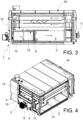
- the supply duct C includes fans V which circulate the air in the area of the oven F (the upper one in figure 3 ) through which the products to be treated pass.
- the substantially box-shaped element 2 includes a first inlet opening 4 and at least a second inlet opening 5, for respective (recirculation) air flows directed towards the inside of the oven F.
- system 1 includes at least one burner 6, powered by gas, or LPG, or diesel (which constitutes the first type of fuel supply of system 1).
- the burner 6 is associated with the substantially box-shaped element 2, so as to intercept the flow of air entering through the first inlet opening 4.
- the system 1 also includes at least one heat exchanger 7, or battery (more in detail, a battery of tubes inside which a heating fluid flows); the exchanger 7 constitutes the second type of supply of system 1.
- the exchanger 7 is associated with the substantially box-shaped element 2, so as to intercept the flow of air entering through the second inlet opening 5.
- the system 1 includes first selective occlusion means 8 of the first inlet opening 4.
- system 1 includes second selective occlusion means 9 of the at least one second inlet opening 5.
- the features of the present invention, and in particular the first, second selective occlusion means 8, 9 allow the supply system 1 to be used in multiple configurations of use, and therefore with different supplying modes.
- the air enters duct C both through the first inlet opening 4, intercepting the burner 6, and through the second inlet opening 5, intercepting the exchanger 7.
- both the first selective occlusion means 8 and the second selective occlusion means 9 are inactive.
- the recirculation air enters the duct C only through the first inlet opening 4 (since the first selective occlusion means 8 are inactive), and therefore intercepts the burner 6.
- the second selective occlusion means 9 are instead active, and therefore they prevent the air from entering the oven F through the second inlet opening 5.
- This second configuration of use therefore, can be used in production situations in which it is intended to exploit the peculiar characteristics of air heating obtained with burner 6, powered by gas, or LPG, or diesel (for example, the possibility of quickly reaching high air temperatures).
- the at least one heat exchanger 7 is operational (further single power condition).
- the recirculation air enters the duct C through the second inlet opening 5 (since the second selective occlusion means 9 are inactive), and therefore intercepts the exchanger 7.
- the first selective occlusion means 8 are instead active, and therefore they prevent the air from entering the oven F through the first inlet opening 4.
- This third configuration of use therefore, can be used in production situations in which it is intended to exploit the peculiar characteristics of air heating obtained with at least one heat exchanger 7 of a specific type.
- the heat exchanger 7, or battery, of the system 1 according to the present invention can be of different types, in relation to the specific production needs.
- the exchanger 7 can be of the type powered by oil, steam, superheated water, or other types, without limitations to the purposes of the present invention.
- the substantially box-shaped element 2 includes a first wall 10.
- this first wall 10 can be a front (or possibly rear) wall, with reference to the main direction of development of the oven F to which the system 1 is associated.
- the burner 6 penetrates inside the volume enclosed by the substantially box-shaped element 2, which is, in turn, in fluid communication with the duct C.
- the substantially box-shaped element 2 also includes at least a second wall 11.
- At least a second wall 11 can be a side wall, with reference to the main direction of development of the oven F to which the system 1 is associated.
- At least a second wall 11 can be perpendicular to the first wall 10.
- the second inlet opening 5 is created in the at least one second wall 11.
- the exchanger 7 is associated, with the substantially box-shaped element 2, at such second wall 11, in such a way as to be hit by the air flow which circulates inside the oven F and enters the duct C through the second inlet opening 5.
- the substantially box-shaped element 2 also includes a third wall 12.
- This third wall 12 can be an upper wall, with reference to the main direction of development of the oven F to which the system 1 is associated.
- the third wall 12 can therefore be perpendicular to both the first wall 10 and the second wall 11.
- the first inlet opening 4 is made in the third wall 12 of the substantially box-shaped element 2.
- the system 1 comprises a first filter 13.
- the first filter 13 can be associated, in a removable manner, with the first inlet opening 4.
- the first filter 13 is therefore arranged, in use, along a horizontal plane.
- the first filter 13 is preferably of the mesh type; it has the function of preventing impurities (such as fluff, fiber residues) or foreign bodies from entering the duct C through the first inlet opening 4.
- the first filter 13 may include a handle portion, to be able to be inserted/extracted into/from the first inlet opening 4 (for example via sliding guides), for cleaning and maintenance reasons.
- the system 1 comprises a second filter 14.
- the second filter 14 can be associated, in a removable manner, with the second inlet opening 5.
- the second filter 14 is therefore arranged, in use, according to a vertical plane.
- the second filter 14 is preferably of the mesh type; it has the function of preventing impurities or foreign bodies from entering the duct C through the second inlet opening 5.
- the second filter 14 may include a handle portion, to be able to be inserted/extracted into/from the second inlet opening 5 (for example via sliding guides), for cleaning and maintenance reasons.
- the first selective occlusion means 8 comprise a first screen 15.
- the first screen 15 can be associated, in a removable manner, with the first inlet opening 4.
- the first screen 15 includes a solid body with a substantially laminar shape, which completely prevents the passage of air.
- the first screen 15 slides along respective guides: it can be moved towards the center of the duct C, to open the first inlet opening 4 without the need to extract it.
- the second selective occlusion means 9 comprise a second screen 16.
- the second screen 16 can be associated, in a removable manner, with the second inlet opening 5.
- the second screen 16 is hinged at the second inlet opening 5, and can be moved using a special handle 17, accessible from the outside of the oven F.
- the second screen 16 is therefore mobile between a raised closing position of the second inlet opening 5, and a lowered opening position of the second inlet opening 5.
- the second screen 16 includes a solid body with a substantially laminar shape, which completely prevents the passage of air.
- both the burner 6 and the at least one exchanger 7 are operational (dual power supply active).
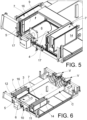
- both the first selective occlusion means 8 and the second selective occlusion means 9 are inactive (i.e. the first screen 15 and the second screen 16 are removed, respectively, from the first inlet opening 4 and from the second inlet opening 5).
- the first filter 13 and the second filter 14 are inserted respectively at the first inlet opening 4 and the second inlet opening 5, to prevent impurities from entering the duct C.
- the second screen 16 (or each screen 16) is raised to occlude the second inlet opening 5 (or each inlet opening 5) so as to prevent the passage of air through it.
- the recirculated air can enter the duct C of the oven F only through the first inlet opening 4, thus intercepting the burner 6.
- the second screen 16 is lowered from the second inlet opening 5 (or each screen 16 from each inlet opening 5).
- the first screen 15 is inserted at the first inlet opening 4, which prevents the passage of air through the aforementioned first inlet opening 4.
- FIG. 10-14 Another embodiment of system 1 according to the invention is illustrated in figures 10-14 .
- This embodiment differs from the previous one due to the conformation and configuration of the first and second selective occlusion means 8, 9.
- the first selective occlusion means 8 comprise a first filter 13 and a second filter 15 which are extractable and constructionally similar, and therefore interchangeable with each other.
- the second selective occlusion means 9 comprise a second filter 14 and a second filter 16 which are also extractable and constructionally similar, and therefore interchangeable with each other.
- Figure 10 refers to the first configuration of use of the system 1 according to the invention, in which both the burner 6 and the exchanger 7 are operational (dual power supply active).
- both the first selective occlusion means 8 and the second selective occlusion means 9 are inactive (i.e. the first screen 15 and the second screen 16 are removed, respectively, from the first inlet opening 4 and from the second inlet opening 5).
- the first filter 13 and the second filter 14 are inserted respectively at the first inlet opening 4 and the second inlet opening 5, to prevent impurities from entering the oven.
- FIGs 11 , 12 refer instead to two successive phases of the preparation of the system 1 in the second configuration of use, in which only the burner 6 is operational (single power supply condition).
- the first filter 13 and the second filter 14 are removed respectively from the first inlet opening 4 and from the second inlet opening 5 (as indicated by the arrows).
- the second screen 16 is inserted at the second inlet opening 5 (as indicated by the arrows), which prevents the passage of air through the aforementioned second inlet opening 5.
- the recirculated air can enter the duct C of the oven F only through the first inlet opening 4, thus intercepting the burner 6.
- FIGS 13 , 14 refer instead to two subsequent phases of the preparation of the system 1 in the third configuration of use, in which only the heat exchanger 7 is operational (further single power supply condition).
- the first screen 15 is inserted at the first inlet opening 4, which prevents the passage of air through the aforementioned first inlet opening 4, while the second filter 14 is inserted at the second inlet opening 5 (as indicated by the arrows).
- the recirculation air can enter the duct C of the oven F only through the second inlet opening 5, thus intercepting the exchanger 7.
- the system 1 according to the invention therefore allows the heating of the oven F to be managed as needed, completely independently, without interference, without load losses and with a notable reduction in process energy costs, also eliminating any residual risk and/or contamination between the two heating devices.
- the user can advantageously carry out both processes on the same system, in particular by operating with the second use configuration, in which only the burner 6 is operational: the burner 6, in fact, allows to reach the temperature of 200°C without any particular problems.
- burner 6 instead of exchanger 7, allows the industrial plant (and therefore oven F) to function even during the third shift, in which steam is not available.
- the system 1 therefore allows the use of a double supply system, maintaining the technical conditions of a single supply machine unchanged. Furthermore, the system 1 allows to obtain a high versatility of use without generating, for the same energy used, any load loss, and without penalizing the energy used/production ratio.
- the system 1 does not present clogging problems greater than those of systems with a single battery or exchanger.
- the system 1 also eliminates:
- the system 1 according to the invention is also configured to switch in a very practical and quick way from one configuration to another (and therefore from one power system to another).
- the system 1 can include two exchangers 7 (of the same type or different types) arranged symmetrically with respect to the burner 6.
Landscapes
- Engineering & Computer Science (AREA)
- Mechanical Engineering (AREA)
- General Engineering & Computer Science (AREA)
- Drying Of Solid Materials (AREA)
- Feeding And Controlling Fuel (AREA)
Applications Claiming Priority (1)
| Application Number | Priority Date | Filing Date | Title |
|---|---|---|---|
| IT102022000021555A IT202200021555A1 (it) | 2022-10-19 | 2022-10-19 | Sistema a doppia alimentazione per forni |
Publications (1)
| Publication Number | Publication Date |
|---|---|
| EP4357713A1 true EP4357713A1 (de) | 2024-04-24 |
Family
ID=84943558
Family Applications (1)
| Application Number | Title | Priority Date | Filing Date |
|---|---|---|---|
| EP23204567.4A Pending EP4357713A1 (de) | 2022-10-19 | 2023-10-19 | Doppelversorgungssystem für öfen |
Country Status (2)
| Country | Link |
|---|---|
| EP (1) | EP4357713A1 (de) |
| IT (1) | IT202200021555A1 (de) |
Citations (4)
| Publication number | Priority date | Publication date | Assignee | Title |
|---|---|---|---|---|
| US4240787A (en) * | 1979-06-19 | 1980-12-23 | Jamaluddin Aziz A | Drying oven with heat reclamation and air pollution control system |
| US4878839A (en) * | 1987-09-08 | 1989-11-07 | Ws Warmeprozesstechnik Gmbh | Non-polluting hot gas generating system |
| US5375586A (en) * | 1993-08-11 | 1994-12-27 | Inter-City Products Corporation (Usa) | Condensate isolator and drainage system for furnace |
| AU2020342698A1 (en) * | 2019-09-03 | 2022-04-07 | Sl-Technik Gmbh | Biomass heating plant with optimised flue gas treatment |
-
2022
- 2022-10-19 IT IT102022000021555A patent/IT202200021555A1/it unknown
-
2023
- 2023-10-19 EP EP23204567.4A patent/EP4357713A1/de active Pending
Patent Citations (4)
| Publication number | Priority date | Publication date | Assignee | Title |
|---|---|---|---|---|
| US4240787A (en) * | 1979-06-19 | 1980-12-23 | Jamaluddin Aziz A | Drying oven with heat reclamation and air pollution control system |
| US4878839A (en) * | 1987-09-08 | 1989-11-07 | Ws Warmeprozesstechnik Gmbh | Non-polluting hot gas generating system |
| US5375586A (en) * | 1993-08-11 | 1994-12-27 | Inter-City Products Corporation (Usa) | Condensate isolator and drainage system for furnace |
| AU2020342698A1 (en) * | 2019-09-03 | 2022-04-07 | Sl-Technik Gmbh | Biomass heating plant with optimised flue gas treatment |
Also Published As
| Publication number | Publication date |
|---|---|
| IT202200021555A1 (it) | 2024-04-19 |
Similar Documents
| Publication | Publication Date | Title |
|---|---|---|
| US20120074124A1 (en) | Heating cooking appliance | |
| EP4357713A1 (de) | Doppelversorgungssystem für öfen | |
| EP3176297B1 (de) | Waschtrockner | |
| CN108087049A (zh) | 一种工业供汽系统 | |
| CN102080818A (zh) | 一种模块组合式余热锅炉 | |
| CN102536361A (zh) | 烧结余热与饱和蒸汽综合利用系统 | |
| CA2962125C (en) | A heat recovery unit and power plant | |
| CN109084290B (zh) | 一种节能模块蒸汽炉 | |
| BR102023021726A2 (pt) | Sistema de fornecimento duplo para fornos | |
| JP5740887B2 (ja) | 耐炎化炉熱媒加熱システム | |
| CN215572299U (zh) | 一种组合型节能换热系统 | |
| EP3257422B1 (de) | Geschirrspülmaschine | |
| CN201981407U (zh) | 一种工业烘干机空气加热装置 | |
| EP3257423B1 (de) | Geschirrspülmaschine | |
| CN214406504U (zh) | 一种便于温控调节的新型导热油炉 | |
| CN211432264U (zh) | 一种蒸汽发生器及烹饪设备 | |
| CN208333103U (zh) | 一种铝棒热剪炉 | |
| CN214736830U (zh) | 一种具有独立烘干装置的衣物洗护系统 | |
| US20180306518A1 (en) | Heat exchanger arrangement for an industrial production plant | |
| CN110250902A (zh) | 环保型双门蒸柜 | |
| CN112294118A (zh) | 换热器、排出容器和咖啡分配机 | |
| KR101006761B1 (ko) | 증기보일러 부설 과열기 겸 온수가열기 | |
| NL8005326A (nl) | Inrichting voor het stomen van textielstoffen. | |
| CN218442998U (zh) | 一种新型的减温减压装置 | |
| CN100476064C (zh) | 全自动可调高温定型箱 |
Legal Events
| Date | Code | Title | Description |
|---|---|---|---|
| PUAI | Public reference made under article 153(3) epc to a published international application that has entered the european phase |
Free format text: ORIGINAL CODE: 0009012 |
|
| STAA | Information on the status of an ep patent application or granted ep patent |
Free format text: STATUS: THE APPLICATION HAS BEEN PUBLISHED |
|
| AK | Designated contracting states |
Kind code of ref document: A1 Designated state(s): AL AT BE BG CH CY CZ DE DK EE ES FI FR GB GR HR HU IE IS IT LI LT LU LV MC ME MK MT NL NO PL PT RO RS SE SI SK SM TR |
|
| STAA | Information on the status of an ep patent application or granted ep patent |
Free format text: STATUS: REQUEST FOR EXAMINATION WAS MADE |
|
| 17P | Request for examination filed |
Effective date: 20241024 |
|
| RBV | Designated contracting states (corrected) |
Designated state(s): AL AT BE BG CH CY CZ DE DK EE ES FI FR GB GR HR HU IE IS IT LI LT LU LV MC ME MK MT NL NO PL PT RO RS SE SI SK SM TR |