EP4357730A1 - Abweichungsmessvorrichtung - Google Patents
Abweichungsmessvorrichtung Download PDFInfo
- Publication number
- EP4357730A1 EP4357730A1 EP22824010.7A EP22824010A EP4357730A1 EP 4357730 A1 EP4357730 A1 EP 4357730A1 EP 22824010 A EP22824010 A EP 22824010A EP 4357730 A1 EP4357730 A1 EP 4357730A1
- Authority
- EP
- European Patent Office
- Prior art keywords
- substrate
- center
- positioning claw
- arm
- moving arm
- Prior art date
- Legal status (The legal status is an assumption and is not a legal conclusion. Google has not performed a legal analysis and makes no representation as to the accuracy of the status listed.)
- Pending
Links
Images






Classifications
-
- G—PHYSICS
- G01—MEASURING; TESTING
- G01B—MEASURING LENGTH, THICKNESS OR SIMILAR LINEAR DIMENSIONS; MEASURING ANGLES; MEASURING AREAS; MEASURING IRREGULARITIES OF SURFACES OR CONTOURS
- G01B21/00—Measuring arrangements or details thereof, where the measuring technique is not covered by the other groups of this subclass, unspecified or not relevant
- G01B21/02—Measuring arrangements or details thereof, where the measuring technique is not covered by the other groups of this subclass, unspecified or not relevant for measuring length, width, or thickness
- G01B21/04—Measuring arrangements or details thereof, where the measuring technique is not covered by the other groups of this subclass, unspecified or not relevant for measuring length, width, or thickness by measuring coordinates of points
-
- H—ELECTRICITY
- H10—SEMICONDUCTOR DEVICES; ELECTRIC SOLID-STATE DEVICES NOT OTHERWISE PROVIDED FOR
- H10P—GENERIC PROCESSES OR APPARATUS FOR THE MANUFACTURE OR TREATMENT OF DEVICES COVERED BY CLASS H10
- H10P74/00—Testing or measuring during manufacture or treatment of wafers, substrates or devices
- H10P74/20—Testing or measuring during manufacture or treatment of wafers, substrates or devices characterised by the properties tested or measured, e.g. structural or electrical properties
- H10P74/203—Structural properties, e.g. testing or measuring thicknesses, line widths, warpage, bond strengths or physical defects
-
- G—PHYSICS
- G01—MEASURING; TESTING
- G01B—MEASURING LENGTH, THICKNESS OR SIMILAR LINEAR DIMENSIONS; MEASURING ANGLES; MEASURING AREAS; MEASURING IRREGULARITIES OF SURFACES OR CONTOURS
- G01B21/00—Measuring arrangements or details thereof, where the measuring technique is not covered by the other groups of this subclass, unspecified or not relevant
- G01B21/02—Measuring arrangements or details thereof, where the measuring technique is not covered by the other groups of this subclass, unspecified or not relevant for measuring length, width, or thickness
- G01B21/06—Measuring arrangements or details thereof, where the measuring technique is not covered by the other groups of this subclass, unspecified or not relevant for measuring length, width, or thickness specially adapted for measuring length or width of objects while moving
-
- H—ELECTRICITY
- H10—SEMICONDUCTOR DEVICES; ELECTRIC SOLID-STATE DEVICES NOT OTHERWISE PROVIDED FOR
- H10P—GENERIC PROCESSES OR APPARATUS FOR THE MANUFACTURE OR TREATMENT OF DEVICES COVERED BY CLASS H10
- H10P72/00—Handling or holding of wafers, substrates or devices during manufacture or treatment thereof
- H10P72/06—Apparatus for monitoring, sorting, marking, testing or measuring
- H10P72/0606—Position monitoring, e.g. misposition detection or presence detection
-
- H—ELECTRICITY
- H10—SEMICONDUCTOR DEVICES; ELECTRIC SOLID-STATE DEVICES NOT OTHERWISE PROVIDED FOR
- H10P—GENERIC PROCESSES OR APPARATUS FOR THE MANUFACTURE OR TREATMENT OF DEVICES COVERED BY CLASS H10
- H10P72/00—Handling or holding of wafers, substrates or devices during manufacture or treatment thereof
- H10P72/50—Handling or holding of wafers, substrates or devices during manufacture or treatment thereof for positioning, orientation or alignment
-
- H—ELECTRICITY
- H10—SEMICONDUCTOR DEVICES; ELECTRIC SOLID-STATE DEVICES NOT OTHERWISE PROVIDED FOR
- H10P—GENERIC PROCESSES OR APPARATUS FOR THE MANUFACTURE OR TREATMENT OF DEVICES COVERED BY CLASS H10
- H10P72/00—Handling or holding of wafers, substrates or devices during manufacture or treatment thereof
- H10P72/70—Handling or holding of wafers, substrates or devices during manufacture or treatment thereof for supporting or gripping
- H10P72/76—Handling or holding of wafers, substrates or devices during manufacture or treatment thereof for supporting or gripping using mechanical means, e.g. clamps or pinches
- H10P72/7602—Handling or holding of wafers, substrates or devices during manufacture or treatment thereof for supporting or gripping using mechanical means, e.g. clamps or pinches the wafers being placed on a robot blade or gripped by a gripper for conveyance
-
- H—ELECTRICITY
- H10—SEMICONDUCTOR DEVICES; ELECTRIC SOLID-STATE DEVICES NOT OTHERWISE PROVIDED FOR
- H10P—GENERIC PROCESSES OR APPARATUS FOR THE MANUFACTURE OR TREATMENT OF DEVICES COVERED BY CLASS H10
- H10P72/00—Handling or holding of wafers, substrates or devices during manufacture or treatment thereof
- H10P72/70—Handling or holding of wafers, substrates or devices during manufacture or treatment thereof for supporting or gripping
- H10P72/76—Handling or holding of wafers, substrates or devices during manufacture or treatment thereof for supporting or gripping using mechanical means, e.g. clamps or pinches
- H10P72/7604—Handling or holding of wafers, substrates or devices during manufacture or treatment thereof for supporting or gripping using mechanical means, e.g. clamps or pinches the wafers being placed on a susceptor, stage or support
- H10P72/7606—Handling or holding of wafers, substrates or devices during manufacture or treatment thereof for supporting or gripping using mechanical means, e.g. clamps or pinches the wafers being placed on a susceptor, stage or support characterised by edge clamping, e.g. clamping ring
-
- H—ELECTRICITY
- H10—SEMICONDUCTOR DEVICES; ELECTRIC SOLID-STATE DEVICES NOT OTHERWISE PROVIDED FOR
- H10P—GENERIC PROCESSES OR APPARATUS FOR THE MANUFACTURE OR TREATMENT OF DEVICES COVERED BY CLASS H10
- H10P74/00—Testing or measuring during manufacture or treatment of wafers, substrates or devices
- H10P74/20—Testing or measuring during manufacture or treatment of wafers, substrates or devices characterised by the properties tested or measured, e.g. structural or electrical properties
-
- H—ELECTRICITY
- H10—SEMICONDUCTOR DEVICES; ELECTRIC SOLID-STATE DEVICES NOT OTHERWISE PROVIDED FOR
- H10W—GENERIC PACKAGES, INTERCONNECTIONS, CONNECTORS OR OTHER CONSTRUCTIONAL DETAILS OF DEVICES COVERED BY CLASS H10
- H10W46/00—Marks applied to devices, e.g. for alignment or identification
-
- H—ELECTRICITY
- H10—SEMICONDUCTOR DEVICES; ELECTRIC SOLID-STATE DEVICES NOT OTHERWISE PROVIDED FOR
- H10W—GENERIC PACKAGES, INTERCONNECTIONS, CONNECTORS OR OTHER CONSTRUCTIONAL DETAILS OF DEVICES COVERED BY CLASS H10
- H10W46/00—Marks applied to devices, e.g. for alignment or identification
- H10W46/201—Marks applied to devices, e.g. for alignment or identification located on the periphery of wafers, e.g. orientation notches or lot numbers
Definitions
- the present invention generally relates to the field of semiconductor manufacturing and, more particularly, to a device for measuring the deviation between the center of a substrate and a standard center.
- the substrate In most processes of the substrate processing process, the substrate is rotated about an axis passing through the center of the substrate as the rotation axis, and the center of the substrate needs to be aligned with the center of the substrate chuck, that is, the standard center.
- the center of the substrate In the substrate manufacturing process, due to the limitation of the process level, there may be deviations between the shape and size of the substrate and the shape and size of the standard substrate. Therefore, when the substrate is placed, the center of the substrate may deviate from the standard center, which will cause some problems.
- the substrate edge cleaning device the substrate is clamped by the substrate chuck, and driven by the rotary drive mechanism, rotates around the rotation axis, and the cleaning nozzle is located near the edge of the substrate to clean the edge of the substrate. If there is a deviation between the center of the substrate and the standard center, the distance between the cleaning nozzle and the periphery of the substrate is not a preset value, resulting in an unsatisfactory cleaning result.
- An object of the present invention is to propose a device for measuring the deviation between the center of a substrate and a standard center.
- an embodiment of the present invention provides a deviation measurement device for measuring the deviation between the center of the substrate and the standard center, comprising a reference arm, a moving arm and a first linear module.
- a first positioning claw is disposed on the moving arm, and the first positioning claw is configured to abut against two points on the edge of the substrate.
- a second positioning claw is disposed on the reference arm, and the second positioning claw is configured to abut against two points on the edge of the substrate.
- the moving arm is disposed opposite to the reference arm.
- a connecting line between a center of the first positioning claw and a center of the second positioning claw is a straight line L, and the straight line L passes through a standard center.
- the first linear module is connected to the moving arm, and the moving arm can be translated along the straight line L under the driving of the first linear module, and the first positioning claw pushes the substrate until the first positioning claw and the second positioning claw are in contact with the edge of the substrate at the same time, the substrate center is located on the straight line L.
- the deviation between the substrate center and the standard center can be calculated according to coordinates of the reference arm and the moving arm, and the substrate may be an oval substrate or a circular substrate.
- a deviation measurement device for measuring a deviation between a substrate center and a standard center, comprising a reference arm, a moving arm and a first linear module.
- the reference arm is provided with a positioning claw for abutting against two points on the edge of the substrate.
- a contact head and a pressure sensor are disposed on the moving arm.
- the contact head is configured to abut against a point on the edge of the substrate.
- the pressure sensor is connected to the contact head, and the pressure sensor measures a pressure between the edge of the substrate and the contact head.
- the moving arm is opposite to the reference arm.
- a connecting line between the center of the positioning claw and the center of the contact head is a straight line L, and the straight line L passes through a standard center.
- the first linear module is connected to the moving arm, and the moving arm can be translated along the straight line L under the driving of the first linear module, and during measurement, the moving arm starts from an initial coordinate and pushes the substrate until the positioning claw and the contact head are in contact with the edge of the substrate at the same time.
- the center of the substrate is located on the straight line L, and the moving arm is located at an end coordinate, then, the diameter d1 of the substrate is calculated to obtain the deviation n between the center of the substrate and the standard center.
- d0 a standard diameter
- the positioning claw is V-shaped
- ⁇ half of the opening angle of the positioning claw
- m ⁇ 1- ⁇ 0
- ⁇ 1 a translation distance between the initial coordinate and the end coordinate of the moving arm
- ⁇ 0 is a standard translation distance of the moving arm
- the standard translation distance is obtained in advance
- a method for obtaining the standard translation distance is as follows: A substrate having a standard diameter d0 is used as a substrate during measurement, and an obtained translation distance between an initial coordinate and an end coordinate of the moving arm is the standard translation distance.
- the embodiment of the present invention discloses a deviation measurement device, which measures the deviation between the center of the substrate and the standard center.
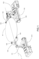
- the deviation measurement device includes a reference arm 101, a first linear module 102 and a moving arm 103.
- the moving arm 103 is provided with a first positioning claw 104, which is used to abut against two points on the edge of the substrate W.
- the reference arm 101 is provided with a second positioning claw 105, which is used to abut against two points on the edge of the substrate W.
- the reference arm 101 is arranged opposite to the moving arm 103, and the connecting line between the center of the first positioning claw 104 and the center of the second positioning claw 105 is a straight line L, and the straight line L passes through the standard center, and the first linear module 102 is connected with the moving arm 103, and the moving arm 103 can translate along the straight line L driven by the first linear module 102.
- the first positioning claw 104 pushes the substrate W until the first positioning claw 104 and the second positioning claw 105 contact with the edge of the substrate W at the same time. At this time, the center of the substrate W is located on the straight line L.
- the deviation between the center point of the substrate W and the standard center point can be calculated according to the coordinates of the reference arm 101 and the moving arm 103.
- x 1 is the center point of the first positioning claw 104
- x 2 is the center point of the second positioning claw 105.
- the center point O of the substrate W' is the midpoint of x 1 and x 2
- the center point O of the substrate W' is also the standard center point O'
- the substrate W is a circular substrate with non-standard size, when the first positioning claw 104 and the second positioning claw 105 are in contact with the edge of the substrate W at the same time, the center point O of the substrate W is the midpoint of x 1 and x 2 .
- the center point O of the substrate W deviates from the standard center point O'. Since the first positioning claw 104 is relatively stationary to the moving arm 103, and the second positioning claw 105 is relatively stationary to the reference arm 101, the coordinate of the moving arm 103 can be regarded as the coordinate of the center point x 1 of the first positioning claw 104, and the coordinate of the reference arm 101 can be regarded as the coordinate of the center point x 2 of the second positioning claw 105.
- the deviation between the center point O of the substrate W and the standard center point O' can be calculated according to the coordinate of the moving arm 103 and the coordinate of the reference arm 101.
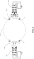
- the substrate W may be a circular substrate with a notch. As shown in Figure 3 , when the first positioning claw 104 and the second positioning claw 105 are in contact with the edge of the substrate W at the same time, if the notch is just in the vicinity of the second positioning claw 105, only a point H of the second positioning claw 105 is in contact with the edge of the substrate W, because there are two points I and J of the edge of the substrate W in contact with the first positioning claw 104, so the existence of the notch will not affect the calculation of the center point position of the substrate W.
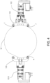
- the substrate W may also be a circular substrate with a flat edge, as shown in Fig. 4 , the existence of the flat edge will not affect the calculation of the center point position of the substrate W.
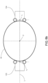
- the substrate W may also be an oval substrate.
- the thrust F exerted by the first positioning claw 104 on the substrate W will cause the substrate W to rotate counterclockwise, and the substrate W passes through the position shown in Fig. 5b and ultimately reaches the position shown in Fig.
- the thrust F exerted by the first positioning claw 104 on the substrate W will cause the substrate W to rotate clockwise, so that the substrate W will finally be at the position shown in Fig. 6b .
- the center point O and the major axis of the substrate are located on the straight line L, and the center point O of the substrate W is the midpoint of x 1 and x 2 , x 1 is the center point of the first positioning claw 104, x 2 is the center point of the second positioning claw 105.
- the arc-shaped arrow in Fig. 6a indicates the rotation direction of the substrate W when the first positioning claw 104 pushes the substrate W.
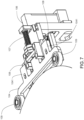
- a pressure sensor 106 is set on the moving arm 103, and the pressure sensor 106 is connected to the first positioning claw 104 for measuring the pressure between the edge of the substrate W and the first positioning claw 104.
- the pressure between the first positioning claw 104 and the substrate W is kept at a constant value, such as 5N or within a set range, for example, between 4.8N-5.2N, which can reduce the error caused by the poor contact between the first positioning claw 104 and the substrate W, and make the calculation of the center point position of the substrate W more accurate.
- the initial coordinate of the reference arm 101 and the initial coordinate of the moving arm 103 can be obtained in advance.
- the coordinate of the reference arm 101 is the initial coordinate of the reference arm 101. Since the displacement amount of the moving arm 103 on the first linear module 102 can be read, the coordinate of the moving arm 103 can be calculated according to the initial coordinate of the moving arm 103 and the displacement amount of the moving arm 103 on the first linear module 102.
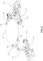
- a displacement sensor 1012 can also be used to obtain the motion amount of the first linear module 102. As shown in Figure 9 , the displacement sensor 1012 can be fixed on the first linear module 102 and disposed opposite to the moving arm 103. After the moving arm 103 moves, the displacement sensor 1012 can measure the moving distance of the moving arm 103, and the moving distance is the displacement amount of the moving arm 103 on the first linear module 102.
- the first positioning claw 104 is connected to the pressure sensor 106 through a spring 107, and the spring 107 plays a cushioning role to prevent the first positioning claw 104 from damaging the substrate W, and the measurement value of the pressure sensor 106 is more accurate.
- One strip protrusion 1041 is disposed on each side of the first positioning claw 104, and two parallel tracks 108 are disposed on the moving arm 103, the two strip protrusions 1041 are connected to the two tracks 108 in a one-to-one correspondence, and the first positioning claw 104 may slide along the track 108.
- the first positioning claw 104 and the second positioning claw 105 are respectively provided with two rollers 109, and the rolling surfaces of the rollers 109 are used to abut against the edge of the substrate W.
- the first positioning claw 104 pushes the substrate W to rotate, rolling friction occurs between the roller 109 and the edge of the substrate W, the edge of the substrate W is not easily damaged.
- the rollers 109 may also be replaced by a circular ball embedded in the heads of the first positioning claw 104 and the second positioning claw 105.
- the deviation measurement device of the embodiment further includes a second linear module 1011, and the second linear module 1011 is connected with the reference arm 101.
- the reference arm 101 and the moving arm 103 may be translated along the straight line L respectively driven by the second linear module 1011 and the first linear module 102.
- the reference arm 101 and the moving arm 103 can move synchronously with the substrate W to align the center of the substrate W with the standard center.
- the displacement amount of the reference arm 101 on the second linear module 1011 can be directly read, or a displacement sensor 1012 can be used to obtain the displacement amount of the reference arm 101 on the second linear module 1011.
- the displacement sensor 1012 may be fixed on the second linear module 1011, and is disposed opposite to the reference arm 101. When the reference arm 101 moves, the displacement sensor 1012 can measure the moving distance of the reference arm 101. The moving distance is a displacement amount of the reference arm 101 on the second linear module 1011.
- the embodiment of the present invention discloses a deviation measurement device, which measures the deviation between the center of the substrate and the standard center.
- the deviation measurement device includes a reference arm 201, a first linear module 202 and a moving arm 203.
- a positioning claw 204 is disposed on the reference arm 201, and the positioning claw 204 is configured to abut against two points on the edge of the substrate.
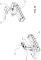
- a contact head 205 and a pressure sensor 206 are disposed on the moving arm 203.
- the contact head 205 is configured to abut against one point on the edge of the substrate, and the pressure sensor 206 is connected to the contact head 205 to measure a pressure between the edge of the substrate and the contact head 205.
- the moving arm 203 is disposed opposite to the reference arm 201, and a connecting line between the center of the positioning claw 204 and the center of the contact head 205 is a straight line L, the straight line L passes through the standard center.
- the first linear module 202 is connected to the moving arm 203, and the moving arm 203 may be driven by the first linear module 202 to translate along the straight line L.
- the moving arm 203 pushes the substrate to make the edge of the substrate be in contact with the positioning claw 204 and the contact head 205, at this time, the center of the substrate is located on the straight line L, and a deviation between the center of the substrate and the standard center may be calculated according to coordinates of the reference arm 201 and the moving arm 203.
- the contact head 205 is connected to the pressure sensor 206 through a spring 207.
- a sliding groove 2010 is disposed on the moving arm 203, and the contact head 205 may slide along the sliding groove 2010.
- a roller 209 is disposed on the contact head 205, the roller surface of the roller 209 is used to abut against the edge of the substrate. If the substrate and the contact head 205 are relatively slid in a process of contacting, the friction between the substrate and the contact head 205 is a rolling friction instead of a sliding friction, and the rolling friction causes less damage to the edge of the substrate.
- the roller 209 may be replaced by a circular ball embedded in the head of the contact head 205.
- the positioning claw 204 and the contact head 205 are in contact with three points on the edge of the substrate, and because the connecting lines among the three points form an isosceles triangle, the center of the circular substrate must be located on the straight line L.
- the following describes the calculation principle of the diameter d1 of the substrate and the deviation n between the center of the substrate and the standard center by taking the standard diameter of 300 mm as an example.
- the dotted circle represents a standard substrate with a diameter d0 of 300 mm
- the solid circle represents a substrate with an unknown diameter (diameter d1)
- the right fold line represents the V-shaped positioning claw 204.
- O is the standard center, i.e. the center of the standard substrate
- P is the center of the substrate of unknown diameter.
- Point A is a contact point between the contact head 205 and the standard substrate
- point B is a contact point between the contact head 205 and the substrate of unknown diameter
- point C is a contact point between the standard substrate and the positioning claw 204
- point D is a contact point between the substrate of unknown diameter and the positioning claw 204.
- the length of AB is defined as m, where m is a directional quantity. When d1 ⁇ 300, m>0, and when d1>300, m ⁇ 0.
- the length of OP is defined as n, and n is also a directional quantity. When P is on the right side of O, n>0, and when P is on the left side of O, n ⁇ 0.
- the angle ⁇ is 1 / 2 of the opening angle of the positioning claw 204.
- n 300 ⁇ d 1 2 sin ⁇
- the diameter d1 of the substrate may be first measured according to Formula (3), and after the diameter d1 is measured, the deviation n between the center of the substrate with unknown diameter and the standard center may be calculated according to Formula (1).
- the device of the embodiment further includes a second linear module 2011.
- the second linear module 2011 is connected to the reference arm 201.
- the reference arm 201 and the moving arm 203 may be translated along the straight line L respectively driven by the second linear module 2011 and the first linear module 202.
- the reference arm 201 and the moving arm 203 may move synchronously with the substrate W to make the center of the substrate W be aligned with the standard center.
- the motion amounts of the first linear module 202 and the second linear module 2011 can be read directly or measured by displacement sensors mounted on the first linear module 202 and the second linear module 2011.
- the displacement sensor on the first linear module 202 is disposed opposite to the moving arm 203, and is configured to measure a moving distance of the moving arm 203
- the displacement sensor on the second linear module 2011 is disposed opposite to the reference arm 201, and is configured to measure a moving distance of the reference arm 201.
Landscapes
- Physics & Mathematics (AREA)
- General Physics & Mathematics (AREA)
- Container, Conveyance, Adherence, Positioning, Of Wafer (AREA)
- A Measuring Device Byusing Mechanical Method (AREA)
- Length Measuring Devices With Unspecified Measuring Means (AREA)
Applications Claiming Priority (2)
| Application Number | Priority Date | Filing Date | Title |
|---|---|---|---|
| CN202110666730.5A CN115479569A (zh) | 2021-06-16 | 2021-06-16 | 偏差测量装置 |
| PCT/CN2022/094167 WO2022262528A1 (zh) | 2021-06-16 | 2022-05-20 | 偏差测量装置 |
Publications (2)
| Publication Number | Publication Date |
|---|---|
| EP4357730A1 true EP4357730A1 (de) | 2024-04-24 |
| EP4357730A4 EP4357730A4 (de) | 2025-07-30 |
Family
ID=84419113
Family Applications (1)
| Application Number | Title | Priority Date | Filing Date |
|---|---|---|---|
| EP22824010.7A Pending EP4357730A4 (de) | 2021-06-16 | 2022-05-20 | Abweichungsmessvorrichtung |
Country Status (6)
| Country | Link |
|---|---|
| US (1) | US20240282644A1 (de) |
| EP (1) | EP4357730A4 (de) |
| JP (1) | JP2024523036A (de) |
| KR (1) | KR20240021875A (de) |
| CN (1) | CN115479569A (de) |
| WO (1) | WO2022262528A1 (de) |
Families Citing this family (1)
| Publication number | Priority date | Publication date | Assignee | Title |
|---|---|---|---|---|
| CN117153760B (zh) * | 2023-11-01 | 2024-04-12 | 迈为技术(珠海)有限公司 | 一种键合片对中机构以及键合片对中方法 |
Family Cites Families (12)
| Publication number | Priority date | Publication date | Assignee | Title |
|---|---|---|---|---|
| JPH1089904A (ja) * | 1996-09-17 | 1998-04-10 | Hitachi Electron Eng Co Ltd | Vノッチウェハ位置決め装置 |
| US6126380A (en) * | 1997-08-04 | 2000-10-03 | Creative Design Corporation | Robot having a centering and flat finding means |
| JP3333724B2 (ja) * | 1997-10-21 | 2002-10-15 | 富士通株式会社 | Xy座標軸のずれ検出方法 |
| EP1856730B1 (de) * | 2005-02-22 | 2010-12-29 | OC Oerlikon Balzers AG | Verfahren zur positionierung eines wafers |
| CN101196394A (zh) * | 2007-09-27 | 2008-06-11 | 上海大学 | 小段圆弧圆度的优化最小二乘评价方法 |
| JP5549655B2 (ja) * | 2011-09-26 | 2014-07-16 | 株式会社安川電機 | ハンドおよびロボット |
| JP6612670B2 (ja) * | 2016-03-31 | 2019-11-27 | 東京応化工業株式会社 | 基板処理装置、及び、基板処理方法 |
| CN205975362U (zh) * | 2016-06-29 | 2017-02-22 | 中交一公局第六工程有限公司 | 一种钢套筒辅助定位装置 |
| CN108151614A (zh) * | 2018-03-02 | 2018-06-12 | 沈阳飞机工业(集团)有限公司 | 一种可调弦长测径装置 |
| CN210180369U (zh) * | 2019-08-01 | 2020-03-24 | 盐城佳奥达机械有限公司 | 一种辊子装配用中心偏差测量仪 |
| CN210689429U (zh) * | 2019-09-10 | 2020-06-05 | 横店集团东磁股份有限公司 | 一种用于检测定子缺口与磁瓦角度的检具 |
| CN212705770U (zh) * | 2020-08-14 | 2021-03-16 | 浙江广合智能科技有限公司 | 一种电极坯料加工位置偏移量检测机构及加工装置 |
-
2021
- 2021-06-16 CN CN202110666730.5A patent/CN115479569A/zh active Pending
-
2022
- 2022-05-20 US US18/571,068 patent/US20240282644A1/en active Pending
- 2022-05-20 JP JP2023577724A patent/JP2024523036A/ja active Pending
- 2022-05-20 WO PCT/CN2022/094167 patent/WO2022262528A1/zh not_active Ceased
- 2022-05-20 KR KR1020247000973A patent/KR20240021875A/ko active Pending
- 2022-05-20 EP EP22824010.7A patent/EP4357730A4/de active Pending
Also Published As
| Publication number | Publication date |
|---|---|
| JP2024523036A (ja) | 2024-06-25 |
| TW202301505A (zh) | 2023-01-01 |
| WO2022262528A1 (zh) | 2022-12-22 |
| EP4357730A4 (de) | 2025-07-30 |
| CN115479569A (zh) | 2022-12-16 |
| KR20240021875A (ko) | 2024-02-19 |
| US20240282644A1 (en) | 2024-08-22 |
Similar Documents
| Publication | Publication Date | Title |
|---|---|---|
| CN102980542B (zh) | 一种多传感器联合标定方法 | |
| EP4357730A1 (de) | Abweichungsmessvorrichtung | |
| CN117080143B (zh) | 一种半导体定位装置 | |
| US20060105555A1 (en) | Display apparatus and control method thereof | |
| TWI739693B (zh) | 量測設備 | |
| US20240110776A1 (en) | Detection Device and Welding Quality Inspection System | |
| CN112665477B (zh) | 用于测试端拾器平面定位精度的检具及方法 | |
| CN111816603A (zh) | 一种基板承载装置及检测装置 | |
| CN119666872A (zh) | 一种晶圆检测点螺旋扫描运动装置及方法 | |
| JP3969819B2 (ja) | 位置合わせ方法及び位置合わせ装置 | |
| JPH08338708A (ja) | 測定手段 | |
| JP2000174102A (ja) | 試料台およびこれを用いた基板評価装置 | |
| CN218600604U (zh) | 检测装置 | |
| JP2006010466A (ja) | 板材の平坦度測定方法および装置 | |
| CN215447862U (zh) | 药用玻璃管直线度测量装置 | |
| CN117884986A (zh) | 一种多面共体光学元件的等离子体抛光装置及抛光方法 | |
| JPH10305319A (ja) | 折曲げ加工機における折曲げ角度測定方法およびその装置ならびにその角度測定装置を用いた折曲げ加工方法およびこの加工方法を用いた折曲げ加工機ならびに角度測定用精度チェックブロック | |
| CN117116831B (zh) | 一种用于晶圆检测的超薄补正装置及操作方法 | |
| CN114527142A (zh) | 一种硅片背检设备和背检方法 | |
| CN220708357U (zh) | 一种平行度测量装置 | |
| CN223770114U (zh) | 晶体定向仪 | |
| CN224124541U (zh) | 一种晶圆量测驱动机构用定位装置 | |
| CN105043290A (zh) | 一种轮廓检测装置及其检测光学非球面的方法 | |
| CN223425852U (zh) | 一种内径测量治具 | |
| CN223691665U (zh) | 一种铜板厚度检测装置 |
Legal Events
| Date | Code | Title | Description |
|---|---|---|---|
| STAA | Information on the status of an ep patent application or granted ep patent |
Free format text: STATUS: THE INTERNATIONAL PUBLICATION HAS BEEN MADE |
|
| PUAI | Public reference made under article 153(3) epc to a published international application that has entered the european phase |
Free format text: ORIGINAL CODE: 0009012 |
|
| STAA | Information on the status of an ep patent application or granted ep patent |
Free format text: STATUS: REQUEST FOR EXAMINATION WAS MADE |
|
| 17P | Request for examination filed |
Effective date: 20240109 |
|
| AK | Designated contracting states |
Kind code of ref document: A1 Designated state(s): AL AT BE BG CH CY CZ DE DK EE ES FI FR GB GR HR HU IE IS IT LI LT LU LV MC MK MT NL NO PL PT RO RS SE SI SK SM TR |
|
| DAV | Request for validation of the european patent (deleted) | ||
| DAX | Request for extension of the european patent (deleted) | ||
| A4 | Supplementary search report drawn up and despatched |
Effective date: 20250626 |
|
| RIC1 | Information provided on ipc code assigned before grant |
Ipc: G01B 21/04 20060101AFI20250620BHEP Ipc: H01L 21/67 20060101ALI20250620BHEP Ipc: H01L 21/68 20060101ALI20250620BHEP Ipc: H01L 21/687 20060101ALI20250620BHEP |