EP4357766A1 - Videoerzeugungsvorrichtung und videoerzeugungsverfahren - Google Patents
Videoerzeugungsvorrichtung und videoerzeugungsverfahren Download PDFInfo
- Publication number
- EP4357766A1 EP4357766A1 EP22825005.6A EP22825005A EP4357766A1 EP 4357766 A1 EP4357766 A1 EP 4357766A1 EP 22825005 A EP22825005 A EP 22825005A EP 4357766 A1 EP4357766 A1 EP 4357766A1
- Authority
- EP
- European Patent Office
- Prior art keywords
- function
- wave
- expression
- scattering field
- imaging
- Prior art date
- Legal status (The legal status is an assumption and is not a legal conclusion. Google has not performed a legal analysis and makes no representation as to the accuracy of the status listed.)
- Pending
Links
Images







Classifications
-
- G—PHYSICS
- G01—MEASURING; TESTING
- G01N—INVESTIGATING OR ANALYSING MATERIALS BY DETERMINING THEIR CHEMICAL OR PHYSICAL PROPERTIES
- G01N22/00—Investigating or analysing materials by the use of microwaves or radio waves, i.e. electromagnetic waves with a wavelength of one millimetre or more
-
- A—HUMAN NECESSITIES
- A61—MEDICAL OR VETERINARY SCIENCE; HYGIENE
- A61B—DIAGNOSIS; SURGERY; IDENTIFICATION
- A61B5/00—Measuring for diagnostic purposes; Identification of persons
- A61B5/05—Detecting, measuring or recording for diagnosis by means of electric currents or magnetic fields; Measuring using microwaves or radio waves
- A61B5/0507—Detecting, measuring or recording for diagnosis by means of electric currents or magnetic fields; Measuring using microwaves or radio waves using microwaves or terahertz waves
-
- G—PHYSICS
- G01—MEASURING; TESTING
- G01S—RADIO DIRECTION-FINDING; RADIO NAVIGATION; DETERMINING DISTANCE OR VELOCITY BY USE OF RADIO WAVES; LOCATING OR PRESENCE-DETECTING BY USE OF THE REFLECTION OR RERADIATION OF RADIO WAVES; ANALOGOUS ARRANGEMENTS USING OTHER WAVES
- G01S13/00—Systems using the reflection or reradiation of radio waves, e.g. radar systems; Analogous systems using reflection or reradiation of waves whose nature or wavelength is irrelevant or unspecified
- G01S13/88—Radar or analogous systems specially adapted for specific applications
- G01S13/89—Radar or analogous systems specially adapted for specific applications for mapping or imaging
-
- G—PHYSICS
- G03—PHOTOGRAPHY; CINEMATOGRAPHY; ANALOGOUS TECHNIQUES USING WAVES OTHER THAN OPTICAL WAVES; ELECTROGRAPHY; HOLOGRAPHY
- G03B—APPARATUS OR ARRANGEMENTS FOR TAKING PHOTOGRAPHS OR FOR PROJECTING OR VIEWING THEM; APPARATUS OR ARRANGEMENTS EMPLOYING ANALOGOUS TECHNIQUES USING WAVES OTHER THAN OPTICAL WAVES; ACCESSORIES THEREFOR
- G03B42/00—Obtaining records using waves other than optical waves; Visualisation of such records by using optical means
-
- G—PHYSICS
- G06—COMPUTING OR CALCULATING; COUNTING
- G06F—ELECTRIC DIGITAL DATA PROCESSING
- G06F17/00—Digital computing or data processing equipment or methods, specially adapted for specific functions
- G06F17/10—Complex mathematical operations
-
- G—PHYSICS
- G01—MEASURING; TESTING
- G01N—INVESTIGATING OR ANALYSING MATERIALS BY DETERMINING THEIR CHEMICAL OR PHYSICAL PROPERTIES
- G01N21/00—Investigating or analysing materials by the use of optical means, i.e. using sub-millimetre waves, infrared, visible or ultraviolet light
- G01N21/17—Systems in which incident light is modified in accordance with the properties of the material investigated
- G01N21/25—Colour; Spectral properties, i.e. comparison of effect of material on the light at two or more different wavelengths or wavelength bands
- G01N21/31—Investigating relative effect of material at wavelengths characteristic of specific elements or molecules, e.g. atomic absorption spectrometry
- G01N21/35—Investigating relative effect of material at wavelengths characteristic of specific elements or molecules, e.g. atomic absorption spectrometry using infrared light
- G01N21/3581—Investigating relative effect of material at wavelengths characteristic of specific elements or molecules, e.g. atomic absorption spectrometry using infrared light using far infrared light; using Terahertz radiation
-
- G—PHYSICS
- G01—MEASURING; TESTING
- G01N—INVESTIGATING OR ANALYSING MATERIALS BY DETERMINING THEIR CHEMICAL OR PHYSICAL PROPERTIES
- G01N21/00—Investigating or analysing materials by the use of optical means, i.e. using sub-millimetre waves, infrared, visible or ultraviolet light
- G01N21/17—Systems in which incident light is modified in accordance with the properties of the material investigated
- G01N21/47—Scattering, i.e. diffuse reflection
- G01N21/4795—Scattering, i.e. diffuse reflection spatially resolved investigating of object in scattering medium
-
- G—PHYSICS
- G01—MEASURING; TESTING
- G01N—INVESTIGATING OR ANALYSING MATERIALS BY DETERMINING THEIR CHEMICAL OR PHYSICAL PROPERTIES
- G01N22/00—Investigating or analysing materials by the use of microwaves or radio waves, i.e. electromagnetic waves with a wavelength of one millimetre or more
- G01N22/02—Investigating the presence of flaws
Definitions
- the present disclosure relates to an imaging device or the like for imaging the structure of a scatterer included in an object that is present in a region by using waves.
- Patent Literatures Patent Literatures 1 to 5.
- the present disclosure provides an imaging device or the like that is capable of imaging the structure of a scatterer included in an object that is present in a region by using a wave and increasing the spatial resolution for imaging the structure of the scatterer while avoiding complication of computational processing.
- An imaging device includes a transmitter row including a plurality of transmitters that are aligned in a straight line and that transmit a wave to a region to be measured, a receiver row including a plurality of receivers and provided at an interval from the transmitter row, the plurality of receivers being aligned in a different straight line parallel to the straight line along which the plurality of transmitters are aligned, and receiving the wave from the region, and an information processing circuit that derives an imaging function in accordance with measurement data and a distance and uses the imaging function to image a structure of a scatterer included in an object that is present in the region, the imaging function corresponding to a scattering field function relating to scattering of the wave, the measurement data being obtained by all or some combinations of the plurality of transmitters and the plurality of receivers, the distance being a distance between the straight line along which the plurality of transmitters are aligned and the different straight line along which the plurality of receivers are aligned.
- An imaging device includes a transmitter row including a plurality of transmitters that are aligned in a straight line and that transmit a wave to a region to be measured, a receiver row including a plurality of receivers and provided at an interval from the transmitter row, the plurality of receivers being aligned in a different straight line parallel to the straight line along which the plurality of transmitters are aligned, and receiving the wave from the region, and an information processing circuit that derives an imaging function in accordance with measurement data and a distance and uses the imaging function to image a structure of a scatterer included in an object that is present in the region, the imaging function corresponding to a scattering field function relating to scattering of the wave, the measurement data being obtained by all or some combinations of the plurality of transmitters and the plurality of receivers, the distance being a distance between the straight line along which the plurality of transmitters are aligned and the different straight line along which the plurality of receivers are aligned.
- the imaging device can acquire enough information as measurement data in accordance with various combinations of the plurality of transmitters in the transmitter row and the plurality of receivers in the receiver row. Since there is spacing between the transmitter row and the receiver row, the imaging device is capable of appropriately transmitting a wave to the region and appropriately receiving a wave from the region. Then, the imaging device is capable of appropriately imaging the structure of the scatterer by using the imaging function derived in accordance with the measurement data on the wave and the distance between the transmitter row and the receiver row.
- the imaging device is capable of simplifying computational processing as compared to the case where the transmitters and the receivers are arranged arbitrarily. Accordingly, the imaging device is capable of avoiding complication of computational processing. That is, the imaging device is capable of imaging the structure of the scatterer included in an object that is present in the region by using a wave and increasing the spatial resolution for imaging the structure of the scatterer while avoiding complication of computational processing.
- the information processing circuit derives the scattering field function in accordance with the measurement data and the distance and derives the imaging function in accordance with the scattering field function
- (x 1 , y 1 , z) represents a transmission position of the wave
- (x 2 , y 2 , z) represents a reception position of the wave
- k represents a wave number of the wave
- D represents the region
- ( ⁇ , ⁇ , ⁇ ) corresponds to
- the imaging device is capable of appropriately deriving the scattering field function and the imaging function in accordance with the measurement data obtained along a plane boundary of the region by using the plurality of transmitters in the transmitter row and the plurality of receivers in the receiver row.
- c represents a velocity of propagation of the wave
- t represents a duration of time from transmission of the wave to reception of the wave.
- the imaging device to analytically derive the solution to the equation satisfied by the scattering field function as the scattering field function. Accordingly, the imaging device is capable of efficiently deriving the appropriate scattering field function.
- the imaging device is capable of imaging the condition of scattering in the region and appropriately imaging the structure of the scatterer included in the object that is present in the region.
- the imaging device is capable of derive the scattering field function that appropriately represents the condition of scatteri ng.
- the imaging device to appropriately reflect the measurement data on the wave and the distance between the transmitter row and the receiver row on the imaging function. Accordingly, the imaging device is capable of deriving the imaging function that appropriately represents the condition of scattering.
- the imaging device may include a plurality of transmitter rows as the transmitter row, a plurality of receiver rows as the receiver row, or a plurality of transmitter rows and a plurality of receiver rows as the transmitter row and the receiver row.
- the imaging device allows the imaging device to acquire enough information as the measurement data in accordance with a plurality of combinations of the transmitter rows and the receiver rows.
- This also allows the imaging device to construct a multistatic relation of two directions that are respectively parallel to and orthogonal to the transmitter row(s) and the receiver row(s). Accordingly, the imaging device is capable of appropriately imaging the structure of the scatterer included in the object that is present in the region.
- the imaging device can appropriately reflect the measurement data on the wave and the distance between the transmitter row and the receiver row on the imaging function.
- the imaging device is capable of deriving the imaging function that appropriately represents the condition of scattering, by performing a linear addition corresponding to the distance between the transmitter row and the receiver row on the measurement data obtained in accordance with a plurality of combinations of the transmitter rows and the receiver rows.
- the imaging device can derive the imaging function that reflects the parameters relating to Debye's relaxation. Accordingly, the imaging device is capable of avoiding accuracy degradation that may occur depending on the frequency of the wave.
- the information processing circuit derives the scattering field function in accordance with the measurement data and the distance and derives the imaging function in accordance with the scattering field function
- (x 1 , y 1 , z 1 ) represents a transmission position of the wave
- (x 2 , y 2 , z 2 ) represents a reception position of the wave
- k represents a wave number of the wave
- D represents the region
- the imaging device can derive the scattering field function that is defined on the precondition that the transmission position and the reception position may have different z coordinates and to derive the imaging function in accordance with the derived scattering field function. Accordingly, the imaging device is capable of appropriately deriving the scattering field function and the imaging function in accordance with the measurement data obtained along a tangential plane of the region having a curved boundary by using the plurality of transmitters in the transmitter row and the plurality of receivers in the receiver row.
- the imaging device to analytically derive the solution to the equation satisfied by the scattering field function as the scattering field function. Accordingly, the imaging device is capable of efficiently deriving the appropriate scattering field function.
- the imaging device to derive the imaging function by using the scattering field function that has received input of the position to be imaged. Accordingly, the imaging device is capable of imaging the condition of scattering in the region and appropriately imaging the structure of the scatterer included in the object that is present in the region.
- the imaging device is capable of deriving the scattering field function that appropriately represents the condition of scattering.
- the imaging device to appropriately reflect the measurement data on the wave and the distance between the transmitter row and the receiver row on the imaging function. Accordingly, the imaging device is capable of deriving the imaging function that appropriately represents the condition of scattering.
- the imaging device can derive the imaging function that reflects the parameters relating to Debye's relaxation. Accordingly, the imaging device is capable of avoiding accuracy degradation that may occur depending on the frequency of the wave.
- An imaging method includes causing a plurality of transmitters included in a transmitter row and aligned in a straight line to transmit a wave to a region to be measured, causing a plurality of receivers included in a receiver row provided at an interval from the transmitter row to receive the wave from the region, the plurality of receivers being aligned in a different straight line that is parallel to the straight line along which the plurality of transmitters are aligned, and deriving an imaging function in accordance with measurement data and a distance and using the imaging function to image a structure of a scatterer included in an object that is present in the region, the imaging function corresponding to a scattering field function relating to scattering of the wave, the measurement data being obtained by all or some combinations of the plurality of transmitters and the plurality of receivers, the distance being a distance between the straight line along which the plurality of transmitters are aligned and the different straight line along which the plurality of receivers are aligned.
- This method enables acquiring enough information as the measurement data in accordance with different combinations of the plurality of transmitters in the transmitter row and the plurality of receivers in the receiver row. Since there is spacing between the transmitter row and the receiver row, it is possible to appropriately transmit the wave to the region and to appropriately receive the wave from the region. Then, it is possible to appropriately image the structure of the scatterer by using the imaging function that is derived in accordance with the measurement data on the wave and the distance between the transmitter row and the receiver row.
- the transmitters and the receivers are constrained to being arranged on the two straight lines, it is possible to simplify computational processing as compared to the case where the transmitters and the receivers are arranged arbitrarily. Accordingly, it becomes possible to avoid complication of computational processing. That is, it is possible to image the structure of the scatterer included in the object that is present in the region by using the wave and to increase the spatial resolution for imaging the structure of the scatterer while avoiding complication of computational processing.
- radio waves such as microwaves are primarily assumed as waves in the following description, the waves are not limited to radio waves such as microwaves.
- Imaging based on scattering may be expressed as scattering tomography.
- an imaging device and an imaging method given in the following description may also be expressed as a scattering tomographic device and a scattering tomographic method, respectively
- An imaging device images the structure of a scatterer included in an object that is present in a region by using a wave.
- the imaging device according to the present embodiment including techniques and theories serving as the basis of the imaging device, will be described in detail.
- the present disclosure describes microwave imaging technology based on a super-array (S-Array) scattering field theory.
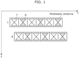
- FIG. 1 is a diagram showing multistatic (MS) antennas according to a reference example.
- Each multistatic antenna includes a plurality of transmitting antenna elements T and a plurality of receiving antenna elements R that are alternately arranged in a row.
- the transmitting antenna elements T and the receiving antenna elements R may also be simply referred to as transmitting elements and receiving elements, respectively
- Each antenna element has a half-wavelength ( ⁇ /2) size.
- the resolution in the y-ax i al direction is a half-wavelength ( ⁇ /2). This does not satisfy the Nyquist criterion of sampling and therefore a phenomenon called aliasing occurs.
- the array antenna of this type can obtain only a very small number of data in relation to its length in the y direction.
- the number of data items obtained by the multistatic antennas shown in FIG. 1 is a total of 18 pairs of data, including each nine pairs obtained at each of positions I and II of the multistatic antennas.
- the number of data that can be obtained when electromagnetically induced coupling is eliminated between each adjacent pair of transmitting and receiving elements is only a total of eight pairs of data, including each four pairs obtained at each of positions I and II. Even in any conceivable arrangement of the antenna elements, it is difficult to realize a single array antenna system that satisfies the Nyquist's theorem of sampling.
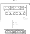
- FIG. 2 is a diagram showing an example of an S-Array multistatic antenna according to the present embodiment.
- the S-Array multistatic antenna may be simply referred to as the S-Array.
- the S-Array multistatic array antenna includes two rows of array antennas including transmitting array antenna TA and receiving array antenna RA.
- the S-Array multistatic array antenna is capable of obtaining 36 pairs of data during transmission and reception.
- An S-Array scattering field theory solves this challenge and realizes a virtual high-density S-Array that satisfies the Nyquist criterion of sampling as shown in the lower section in FIG. 2 . That is, according to the S-Array scattering field theory, two rows of array antennas including transmitting array antenna TA and receiving array antenna RA are theoretically converted into a single row of transmitting and receiving array antennas. Accordingly, ⁇ /4 resolution is achieved in the y direction. Also, arbitrary resolution is achieved in the x direction by scanning in the x direction.
- the S-Array scattering field theory according to the present disclosure is decisively different in the following point from existing scattering field theories relating to two-dimensional array antennas.
- a two-dimensional array antenna is scanned in the x direction in order to satisfy sampling conditions.
- the dimension of a multiple integral in the inverse analysis algorithm for scattering is one dimension higher than that in the S-Array.
- the required analysis time becomes n times or more, where n is the number of samples in the x direction and in the range of, for example, 128 to 256. Therefore, it is difficult to put the existing scattering field analysis methods relating to two-dimensional array antennas into practical use through the ability of existing calculators.
- a signal is transmitted from an arbitrary element in a two-dimensional planar grid array antenna and received by a different arbitrary element in the two-dimensional array antenna. Accordingly, n 4 sets of data are obtained, where n is the number of elements on one side of a tetragonal lattice. Each set of data is time-series data with a bandwidth of 10 GHz or higher.
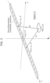
- FIG. 3 is a diagram showing an example of coordinates in the S-Array according to the present embodiment.
- the S-Array is a semi-two-dimensional array antenna configured by two linear array antennas including single-row transmitting array antenna TA and single-row receiving array antenna RA as shown in FIG. 3 .
- transmitting array antenna TA includes n transmitting antenna elements T.
- Receiving array antenna RA includes n receiving antenna elements R.
- the x coordinate of transmitting array antenna TA is expressed as x 1
- the x coordinate of receiving array antenna RA is expressed as x 2
- the distance in the x direction between transmitting array antenna TA and receiving array antenna RA is expressed as d.
- This configuration is capable of obtaining n 2 sets of time-series data, each being an arbitrary combination of n transmitting elements and n receiving elements at each point x in the scanning direction.
- FIG. 4 is an outside drawing of the S-Array according to the present embodiment.
- Transmitting array antenna TA that includes transmitting antenna elements T and receiving array antenna RA that includes receiving antenna elements R are configured away from each other. That is, transmitting antenna elements T and receiving antenna elements R are arranged in semi-two dimensions.
- a method used to image a target object by an imaging device using a one-dimensional array antenna is extremely simple and merely to solve a wave equation given by expression (2-1-1) below.
- ⁇ represents the unknown function
- k represents the wave number
- ⁇ represents the Laplace operator
- a represents the partial differential of each variable with a suffix.
- This method is called monostatic. According to this method, pair elements, each obtained by integrating a transmitting element and a receiving element, are arranged along the y axis. If there are n pair elements for transmission and reception, n sets of data can be obtained. However, the accuracy obtained by this method is basically twice the size of each antenna element for transmission and reception. Therefore, it is difficult to obtain a high-resolution image.
- FIG. 5 is a conceptual diagram showing a one-dimensional multistatic array antenna.
- the spatial resolution becomes twice.
- singles can be received with a high S/N ratio at a range of distances from short distance to long distance. This considerably improves the quality of an ultimate image.
- the amount of data is increased to n times, the time required for reconstitution is also shortened dramatically according to the theory described below.
- ⁇ ( ⁇ , ⁇ , ⁇ ) represents the function of the dielectric constant at point P ( ⁇ , ⁇ , ⁇ ) and corresponds to the reflectance at point P ( ⁇ , ⁇ , ⁇ ).
- Point P ( ⁇ , ⁇ , ⁇ ) corresponds to the reflection point.
- ⁇ ( ⁇ , ⁇ , ⁇ ) is unknown. It is also assumed that the time factor is proportional to exp(-i ⁇ t).
- Expression (2-1-8) is summarized to obtain expression (2-1-9) below.
- Expression (2-1-11) described above is a partial differential equation that has ⁇ in expression (2-1-3) as a solution.
- ⁇ of expression (2-1-2) also satisfies the partial differential equation described above.
- This equation is a four-dimensional pseudo wave equation configured by five variables (t, x, y 1 , y 2 , z).
- ⁇ is obtained as given by expression (2-1-17) below.
- ⁇ x y 1 y 2 z k 1 2 ⁇ 3 ⁇ ⁇ ⁇ ⁇ ⁇ ⁇ ⁇ ⁇ ⁇ ⁇ ⁇ e ⁇ i k x + k y 1 y 1 + k y 2 y 2 a k x k y 1 k y 2 k ⁇ e i k 2 ⁇ k y 1 2 + k 2 ⁇ k y 2 2 2 ⁇ k x 2 z dk x dk y 1 dk y 2
- FIG. 6 is a conceptual diagram showing the relationship between a transmission point and a reception point.
- FIG. 6 shows a situation in which a wave radiated from point r 1 is reflected at point ⁇ ( ⁇ 1 , ⁇ 2 , ...) and returns to point r 2 .
- ⁇ r 1 ⁇ ⁇ ⁇ r 2 , ⁇ represents the signal strength of the wave that comes out from point r 1 and returns to point r 2 by being reflected at point ⁇ .
- G ⁇ r 1 r 2 t represents the function obtained by Fourier transform of function G (r 1 , r 2 , ⁇ ) with respect to ⁇ .
- the value of G (r 1 , r 2 , ⁇ ) at boundary 3D is the value measured by the receiving elements.
- ⁇ (r) is defined as given by expression (2-2-3) below.
- Tr represents the trace operation.
- This ⁇ (r) is the function relating to the gradient of the dielectric constant that is to be obtained in region D.
- L differential operator
- FIG. 7 is a conceptual diagram showing the coordinates of a transmission point and a reception point.
- the transmission point is located at P 1 (x, y 1 , z 1 ) and the reception point is located at P 2 (x, y 2 , z 2 ).
- the wave radiated from transmission point P 1 is reflected at point P ( ⁇ , ⁇ , ⁇ ) and reaches reception point P 2 .
- ⁇ ( ⁇ , ⁇ , ⁇ ) represents the function of the dielectric constant at point ( ⁇ , ⁇ , ⁇ ) and corresponds to the reflectance at point ( ⁇ , ⁇ , ⁇ ).
- Point ( ⁇ , ⁇ , ⁇ ) corresponds to the reflection point.
- ⁇ ( ⁇ , ⁇ , ⁇ ) is unknown.
- k represents the wave number. It is assumed that the time factor is proportional to exp(-i ⁇ t).
- ⁇ ⁇ k x k y 1 k y 2 z 1 z 2 ⁇ ⁇ ⁇ ⁇ ⁇ e i ⁇ t dt ⁇ ⁇ ⁇ ⁇ e ik y 1 y 1 dy 1 ⁇ ⁇ ⁇ ⁇ e ik y 2 y 2 dy 2 ⁇ ⁇ ⁇ ⁇ e ik x x ⁇ x y 1 y 2 z 1 z 2 t dx
- ⁇ x y 1 y 2 z 1 z 2 k 1 2 ⁇ 3 ⁇ ⁇ ⁇ ⁇ ⁇ ⁇ ⁇ ⁇ ⁇ ⁇ ⁇ e ⁇ i k x x + k y 1 y 1 + k y 2 y 2 a k x k y 1 k y 2 k ⁇ e is 1 k x k y 1 k y 2 k z 1 e is 2 k x k y 1 k y 2 k z 2 dk x dk y 1 dk y 2
- FIG. 8 is a conceptual diagram showing the relationship between a transmission point and a reception point during forward scattering.
- Forward scattering differs from backscattering (II-2) in that the z coordinates of all scattered points are included between the z coordinates of transmission point r 1 and reception point r 2 .
- Scattering data is measured as a result of points r 1 and r 2 moving freely over ⁇ D 1 and ⁇ D 2 , respectively, under the constraint that r 1 and r 1 be located at the same x coordinate.
- the scattering field function according to this system is defined by expression (2-3-1) below. [Math.
- ⁇ ⁇ k x k y 1 k y 2 z 1 z 2 ⁇ ⁇ ⁇ ⁇ ⁇ e i ⁇ t dt ⁇ ⁇ ⁇ ⁇ e ik y 1 y 1 dy 1 ⁇ ⁇ ⁇ ⁇ e ik y 2 y 2 dy 2 ⁇ ⁇ ⁇ ⁇ e ik x x ⁇ x y 1 y 2 z 1 z 2 t dx
- ⁇ x y 1 y 2 k 1 2 ⁇ 3 ⁇ ⁇ ⁇ ⁇ ⁇ ⁇ ⁇ ⁇ ⁇ ⁇ ⁇ e ⁇ i k x x + k y 1 y 1 + k y 2 y 2 a k x k y 1 k y 2 k ⁇ e ⁇ is 2 k x k y 1 k y 2 k h dk x dk y 1 dk y 2
- FIG. 9 is a conceptual diagram showing the relationship between a transmission point and a reception point in a plane.
- a microwave radiated from point P 1 is reflected at point P on a target and received at point P 2 .
- Points P 1 and P 2 move to arbitrary points on a grading (two-dimensional antenna array) in a plane. Under this assumption, there are n 4 different microwave paths passing through point P on the target. This large number of paths considerably contributes to an improvement in the quality of an ultimate image. A method for processing such complex data to obtain an image will be described below.
- the radio wave radiated from point P 1 is reflected at point P ( ⁇ , ⁇ , ⁇ ) and received at point P 2 (x 2 , y 2 , z).
- point P is assumed to move in entire region D
- a signal received at P 2 is expressed by the following expression.
- Expression (2-4-7) is summarized to obtain expression (2-4-8) below.
- expression (2-4-8) is converted into expression (2-4-10) below that includes time.
- Expression (2-4-10) described above is a partial differential equation that has the kernel function given by expression (2-4-2) as a solution, and ⁇ also satisfies the above-described partial differential equation by applying differentiation to the kernel of expression (2-4-2).
- This equation is a five-dimensional pseudo wave equation configured by six variables (t, x 1 , y 1 , x 2 , y 2 , z).
- ⁇ is obtained as given by expression (2-4-16) below.
- ⁇ x 1 y 1 x 2 y 2 z k 1 2 ⁇ 3 ⁇ ⁇ ⁇ ⁇ ⁇ ⁇ ⁇ ⁇ ⁇ ⁇ ⁇ ⁇ ⁇ ⁇ ⁇ ⁇ e ⁇ i k x 1 x 1 + k y 1 y 1 e ⁇ i k x 2 x 2 + k y 2 y 2 e i k 2 ⁇ k x 1 2 ⁇ k y 1 2 + k 2 ⁇ k y 2 2 z ⁇ a k x 1 k y 1 k x 2 k y 2 k dk x 1 dk y 1 dk x 2 dk y 2 z ⁇ a k x 1 k y 1 k x 2 k y 2 k dk x 1 dk y 1 dk x 2 dk
- k 1 2 u 2 + k x 2 2 + k y 2 2 ⁇ k x 1 2 ⁇ k y 1 2 2 u 2 + 2 k x 2 2 + k y 2 2 + k x 1 2 + k y 1 2
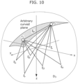
- FIG. 10 is a conceptual diagram showing the relationship between a transmission point and a reception point on a curved plane. Since boundary conditions for curved plane are used, it is assumed that the transmission point and the reception point have different z coordinates. Accordingly, the scattering field function is expressed as given by expression (2-5-1) below. [Math.
- k the wave number. It is assumed that the time factor is proportional to exp(-i ⁇ t). Also, D represents the region and corresponds to D 3 in FIG. 10 .
- ⁇ ⁇ k x 1 k y 1 k x 2 k y 2 z 1 z 2 ⁇ ⁇ ⁇ ⁇ ⁇ e i ⁇ t dt ⁇ ⁇ ⁇ ⁇ e ik y 1 y 1 dy 1 ⁇ ⁇ ⁇ ⁇ e ik y 2 y 2 dy 2 ⁇ ⁇ ⁇ ⁇ e ik x 1 x 1 dx 1 ⁇ ⁇ ⁇ ⁇ e ik x 2 x 2 ⁇ x 1 y 1 x 2 y 2 z 1 z 2 t dx 2
- s 1 and s 2 are obtained as given by expression (2-5-10) below.
- s 1 k 2 ⁇ k x 1 2 ⁇ k y 1 2
- s 2 k 2 ⁇ k x 2 2 ⁇ k y 2 2
- ⁇ x 1 y 1 x 2 y 2 z 1 z 2 k 1 2 ⁇ 4 ⁇ ⁇ ⁇ ⁇ ⁇ ⁇ ⁇ ⁇ ⁇ ⁇ ⁇ ⁇ ⁇ ⁇ ⁇ e ⁇ i k x 1 x 1 + k y 1 y 1 + k x 2 x 2 + k y 2 y 2 a k x 1 k y 1 k x 2 k y 2 ⁇ e is 1 k x 1 k y 1 k x 2 k y 2 z 1 e is 2 k x 1 k y 1 k x 2 k y 2 z 2 dk x 1 dk y 1 dk x 2 dk y 2 y 2 dk y 2
- variable x 2 may be expressed as u.
- Expression (3-1-3) below is obtained by Fourier transform of both sides of expression (3-1-1) with respect to t, x 1 , y 1 , and y 2 .
- [Math. 137] ⁇ u 2 + ⁇ z 2 ⁇ k x 1 2 ⁇ k y 1 2 ⁇ k y 2 2 2 + 4 k 2 ⁇ z 2 + 4 k x 1 2 + k y 1 2 ⁇ u 2 ⁇ k y 2 2 ⁇ ⁇ 0
- s 3 and s 4 are functions with respect to k x1 , k x1 , k y2 , and k as given by expression (3-1-5) below.
- s 3 and s 4 are constants defined by k x1 , k y1 , k y2 , and k.
- s 3 s 3 k x 1 k y 1 k y 2
- k s 4 s 4 k x 1 k y 1 k y 2 k
- Expression (3-1-9) described above is supposed to agree with expression (2-1-17) because it agrees with the solution to the scattering field equation for the one-dimensional array.
- Expression (3-1-11) below is the same as expression (2-1-17).
- [Math. 145] ⁇ x y 1 y 2 z k 1 2 ⁇ 3 ⁇ ⁇ ⁇ ⁇ ⁇ ⁇ ⁇ ⁇ ⁇ ⁇ ⁇ ⁇ e ⁇ i k x + k y 1 y 1 + k y 2 y 2 a k x k y 1 k y 2 k ⁇ e i k 2 ⁇ k y 1 2 + k 2 ⁇ k y 2 2 2 ⁇ k x 2 z dk x dk y 1 dk y 2
- Expression (3-1-14) is summarized to obtain expression (3-1-15) below.
- [Math. 149] k 2 ⁇ k y 1 2 s 3 2 + 2 ik x 1 k 2 ⁇ k y 1 2 + k 2 ⁇ k y 2 2 s 3 ⁇ k x 1 2 k 2 ⁇ k y 2 2 0
- the semi-two-dimensional array is capable of acquiring information on substances included between the x coordinates of the transmission position and the reception position.
- an obstacle with a high dielectric constant it is possible to transmit radio waves and receive waves by circling around the obstacle in the x direction.
- the semi-two-dimensional array is capable of including a larger number of transmitting elements and a larger number of receiving elements. Accordingly, it is possible to more efficiently acquire information.
- FIG. 11 is a diagram showing a multi-row linear array antenna.
- the multi-row linear array antenna shown in FIG. 11 includes single-row transmitting array antenna TA and n-row receiving array antennas RA 1 , RA 2 , RA 3 , ... and RA n .
- the direction of polarization of each antenna element may be in the x direction or in the y direction.
- TA and RA may change their places.
- the MS inverse scattering applied to the semi-two-dimensional array in chapter III-1 is applied to the above-described array.
- the S-Array two-dimensional array has the constraint that TA and RA each be a one-dimensional array. There is a possibility that a scanning probe using this array can acquire a high-quality image and can shorten the scanning time while maintaining the image quality. Alternatively, scanning may be omitted.
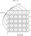
- FIG. 12 is a conceptual diagram showing combinations of transmission positions and reception positions in a multistatic array antenna.
- FIG. 12 shows an S-Array two-dimensional array as a multistatic array antenna.
- the S-Array two-dimensional array is capable of acquiring measurement data at a plurality of reception positions in both of the x and y directions, even if scanning is not performed. That is, the S-Array two-dimensional array has multistatic characteristics in both of the x and y directions. Accordingly, it is possible to acquire enough information and to omit or reduce scanning.
- transmission and reception may change their places.
- a plurality of transmitting array antennas transmit radio waves in sequence. More specifically, a plurality of transmitting elements transmit radio waves in sequence. Even if the transmitting position and the reception position change their places, it is assumed that the amount of received scattering is the same. Accordingly, even if transmission and reception change their places, substantially the same result is obtained.
- linear addition may be performed as in the case of using a plurality of receiving array antennas.
- a plurality of transmitting array antennas and a plurality of receiving array antennas may be used. Then, the transmitting array antennas and the receiving array antennas may be arranged alternately.
- scanning may be performed depending on the S-Array two-dimensional array. In this case, a wider range of information can be obtained.
- the imaging function can be derived from merging of a plurality of scattering field functions that correspond respectively to a plurality of combinations of transmitting array antennas and receiving array antennas.
- the imaging function may be derived by merging a plurality of scattering field functions into a single scattering field function and performing a limit operation on the scattering field function.
- Each of the scattering field functions may be a scattering field function expressed as given by expression (3-1-23).
- the merging may be linear addition.
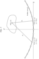
- FIG. 13 is a diagram showing a semi-two-dimensional array antenna on a curved plane.
- the curved plane has a large curvature, it is not permitted to ignore the inclination of the array antenna and to ignore a change in distance between antenna elements in the x-y plane depending on the place.
- the curvature of the curved plane is not so large, the distance between elements in the x-y plane may be regarded approximately constant.
- ⁇ is expressed as given by expression (3-3-7) below.
- [Math. 166] ⁇ x 1 y 1 x 2 y 2 z 1 z 2 k 1 2 ⁇ 3 ⁇ ⁇ ⁇ ⁇ ⁇ ⁇ ⁇ ⁇ ⁇ ⁇ ⁇ e ⁇ i k x 1 x 1 + k y 1 y 1 + k y 2 y 2 b k x 1 k y 1 k y 2 k e s 3 x 2 e s 4 z 1 e s 5 z 2 dk x 1 dk y 1 dk y 2
- Expression (3-3-20) described above is expressed given by as expression (3-3-21) below using data ⁇ obtained by measurement conducted on the boundary.
- ⁇ x I y I y J z I z J k ⁇ x 1 ⁇ x I ⁇ y 1 ⁇ y I ⁇ y 2 ⁇ x J 1 2 ⁇ 3 ⁇ ⁇ ⁇ ⁇ ⁇ ⁇ ⁇ ⁇ ⁇ ⁇ ⁇ ⁇ e ⁇ i k x 1 x 1 + k y 1 y 1 + k y 2 y 2 a I , J k x 1 + is 3 , k y 1 , k y 2 , k ⁇ e s 3 x 1 + d e s 4 z I e s 5 z J d k x 1 + is 3 dk x 1 dk x 1 dk y 1 dk y 2
- ⁇ (x I , y I , y J , z I , z J , k) represents the measurement data on transmission point (x I , y I , z I ), reception point (x I +d, y J , z J ), and wave number k.
- Expression (3-3-22) below is obtained by Fourier transform of both sides of expression (3-3-21).
- Basic variables are k x , k y1 , k y2 , and k z , and the other variables are positively expressed using the basic variables.
- the imaging function is obtained through the following procedure.
- Imaging function ⁇ is obtained by integration with respect to k as given by expression (3-3-28) below.
- the imaging function may be derived by merging of a plurality of scattering field functions that correspond respectively to a plurality of combinations of transmitting array antennas and receiving array antennas.
- the imaging function may be derived by merging a plurality of scattering field functions into a single scattering field function and performing a limit operation on the scattering field function.
- Each of the scattering field functions may be the scattering field function expressed by expression (3-3-26), and the merging may be linear addition.
- the curved boundary of the region does not necessarily have to be a cylindrical surface.
- the above-described process may be applied to not only a tangential plane to a cylindrical surface but also a tangential plane to any other curved boundary.
- the dielectric constant in a region at frequencies of 14 GHz to 20 GHz is approximately 60% of the dielectric constant in a region at frequencies of 1 GHz to 5 GHz.
- ⁇ represents the angular frequency
- ⁇ ( ⁇ ) represents the complex permittivity at ⁇
- i represents the imaginary unit
- ⁇ represents the relaxation time
- ⁇ r ( ⁇ ) represents the real part of the complex permittivity at ⁇
- a, b, and ⁇ represent constants.
- a, b, and ⁇ are parameters indicating the correspondence between a change in frequency and a change in the dielectric constant in accordance with Debye's relaxation.
- c( ⁇ ) represents the velocity of propagation at ⁇
- an imaging function for measuring data with an S-Array near a plane boundary and generating video inside a dielectric dispersive medium is examined. Since the time factor is e -i ⁇ t , integration in expression (3-2-1) is performed with respect to frequency ⁇ , instead of k, when consideration is given to the presence of frequency dependence of the dielectric constant. Accordingly, the imaging function is obtained as given by expressions (4-2-1) and (4-2-2). [Math.
- an imaging function for measuring data with an S-Array near a curved boundary and generating video inside a dielectric dispersive medium is examined. Since the time factor is e -i ⁇ t , integration in expression (3-3-28) is performed with respect to frequency ⁇ , instead of k, when consideration is given to the presence of frequency dependence of the dielectric constant. Accordingly, the imaging function is obtained as given by expressions (4-3-1) and (4-3-2). [Math.
- the waves as used herein may, for example, be radio waves or may be other waves such as microwaves, millimeter waves, or terahertz waves.
- the waves may also be light or sound.
- the object that is present in the region may be a living body, a manufactured material, or a natural material.
- the imaging device may be used for mammography, and the object may be a breast.
- the scatterer included in the object that is present in the region corresponds to a portion that has a physical characteristic different from physical characteristics of surrounding media.
- the physical characteristic is a physical characteristic that corresponds to the reflectance of the waves.
- the physical characteristic may be the dielectric constant.
- the scatterer included in the object may, for example, be a reinforcing steel contained in reinforcing steel concrete or a tumor included in a breast.
- the region to be measured may be equivalent to the region of the object.
- FIG. 14 is a basic schematic diagram of the imaging device according to the present embodiment.
- Imaging device 100 shown in FIG. 14 includes transmitter row 101, receiver row 102, and information processing circuit 103.
- Imaging device 100 may further include display 104.
- Transmitter row 101 is a circuit that transmits waves. Specifically, transmitter row 101 includes a plurality of transmitters 111 aligned in a straight line. Each transmitter 111 transmits a wave. Imaging device 100 may include a plurality of transmitter rows 101 arranged in parallel with one another.
- Receiver row 102 is a circuit that receives waves. Specifically, receiver row 102 includes a plurality of receivers 112 aligned in a different straight line that is parallel to the straight line along which transmitters 111 are aligned. Each receiver 112 receives a wave. Receiver row 102 is arranged at an interval from transmitter row 101. That is, receiver row 102 is spaced from transmitter row 101. Imaging device 100 may include a plurality of receiver rows 102 arranged in parallel with one another.
- Information processing circuit 103 is a circuit that performs information processing. Specifically, information processing circuit 103 images the structure of a scatterer included in an object that is present in a region in accordance with measurement data obtained by transmitter row 101 and receiver row 102. For example, information processing circuit 103 may perform computational processing indicated by the theory described above when imaging the structure of a scatterer in accordance with the measurement data.
- Information processing circuit 103 may also be a computer or a processor of a computer. Information processing circuit 103 may perform information processing by reading out a program from memory and executing the program. Alternatively, information processing circuit 103 may be a dedicated circuit that images the structure of a scatterer in accordance with measurement data.
- information processing circuit 103 may generate an image that indicates the structure of the scatterer.
- information processing circuit 103 may image the structure of the scatterer by outputting the image indicating the structure of the scatterer on display 104 or the like.
- information processing circuit 103 may image the structure of the scatterer by outputting the image indicating the structure of the scatterer to a printer (not shown).
- information processing circuit 103 may image the structure of the scatterer by transmitting the image as electronic data to a different device (not shown) via wired or wireless communication.
- Display 104 is a display device such as a liquid crystal display. Note that display 104 is merely an arbitrary constituent element and is not an essential constituent element. Display 104 may be an external device that is not included in the configuration of imaging device 100.
- FIG. 15 is a flowchart showing basic operations of imaging device 100 shown in FIG. 14 . Specifically, the operations shown in FIG. 15 are performed by the constituent elements of imaging device 100 shown in FIG. 14 such as transmitter row 101, receiver row 102, and information processing circuit 103.
- transmitters 111 of transmitter row 101 transmit waves to a region to be measured (S101). For example, transmitters 111 transmit waves in sequence.
- Receivers 112 of receiver row 102 receive waves from the region (S102). For example, receivers 112 receive waves in parallel.
- the received waves can also be expressed as scattered waves.
- information processing circuit 103 images the structure of a scatterer included in an object that is present in the region, by using measurement data obtained by transmitter rows 101 and receiver rows 102 (S103).
- information processing circuit 103 When imaging the structure of the scatterer, information processing circuit 103 first derives an imaging function that corresponds to a scattering field function relating to scattering of the waves in accordance with measurement data and a distance.
- the measurement data as used herein refers to measurement data obtained by all or some combinations of transmitters 111 and receivers 112.
- the distance as used herein refers to the distance between the straight line along which transmitters 111 are aligned and the straight line along which receivers 112 are aligned. Then, information processing circuit 103 uses the imaging function to image the structure of the scatterer included in the object that is present in the region.
- imaging device 100 is capable of acquiring enough information as the measurement data in accordance with a variety of combinations of transmitters 111 of transmitter row 101 and receivers 112 of receiver row 102. Since there is an interval between transmitter row 101 and receiver row 102, imaging device 100 is capable of appropriately transmitting waves to the region and appropriately receiving waves from the region.
- imaging device 100 is capable of appropriately imaging the structure of the scatterer.
- imaging device 100 is capable of simplifying computational processing as compared with the case where transmitters 111 and receivers 112 are arranged arbitrarily. Accordingly, imaging device 100 is capable of avoiding complication of computational processing. That is, imaging device 100 is capable of imaging the structure of the scatterer included in the object that is present in the region by using waves, and is capable of improving the spatial resolution for imaging the structure of the scatterer while avoiding complication of computational processing.
- information processing circuit 103 may derive the scattering field function in accordance with the measurement data and the distance. Then, information processing circuit 103 may derive the imaging function in accordance with the scattering field function.
- the scattering field function is a function expressed as follows.
- ⁇ x 1 y 1 x 2 y 2 z ⁇ D e ik ⁇ 1 ⁇ 1 e ik ⁇ 2 ⁇ 2 ⁇ ⁇ ⁇ ⁇ d ⁇ d ⁇ d ⁇
- (x 1 , y 1 , z) represents the transmission position of the wave
- (x 2 , y 2 , z) represents the reception position of the wave
- k represents the wave number of the wave
- D represents the region.
- ( ⁇ , ⁇ , ⁇ ) corresponds to the reflecting position of the wave
- ⁇ corresponds to the unknown reflectance at the reflecting position.
- imaging device 100 to derive the scattering field function that is defined on the precondition that the transmission position and the reception position have the same z coordinate and to derive the imaging function in accordance with the derived scattering field function. Accordingly, imaging device 100 is capable of appropriately deriving the scattering field function and the imaging function in accordance with the measurement data obtained along the plane boundary of the region by using transmitters 111 of transmitter row 101 and receivers 112 of receiver row 102.
- information processing circuit 103 may derive the scattering field function by solving the equation satisfied by the scattering field function.
- c represents the velocity of propagation of the wave
- t represents the duration of time from transmission of the wave to reception of the wave.
- imaging device 100 to analytically derive the solution to the equation satisfied by the scattering field function, as the scattering field function. Accordingly, imaging device 100 is capable of efficiently deriving the appropriate scattering field function.
- imaging device 100 to derive the imaging function in accordance with a limit operation performed on the scattering field function. Accordingly, imaging device 100 is capable of imaging the condition of scattering in the region and appropriately imaging the structure of the scatterer included in the object that is present in the region.
- information processing circuit 103 may derive the following as the scattering field function.
- ⁇ x 1 y 1 x 2 y 2 z k 1 2 ⁇ 3 ⁇ ⁇ ⁇ ⁇ ⁇ ⁇ ⁇ ⁇ ⁇ ⁇ ⁇ ⁇ e ⁇ i k x 1 x 1 + k y 1 y 1 + k y 2 y 2 e s 3 x 2 e s 4 z e id k x 1 + is 3 k 2 ⁇ k y 2 2 k 2 ⁇ k y 1 2 + k 2 + k k y 2 2 ⁇ ⁇ ⁇ k x k y 1 k y 2 k d k x 1 + is 3 dk x 1 dk x 1 dk y 1 dk y 2
- k x1 , k y1 , and k y2 represent the wave numbers of the scattering field function with respect to x 1 , y 1 , and y 2 , and d represents the distance.
- ⁇ ⁇ k x k y 1 k y 2 k represents the measurement data that has undergone Fourier transform with respect to x 1 , y 1 , and y 2 .
- imaging device 100 is capable of deriving the scattering field function that appropriately represents the condition of scattering.
- information processing circuit 103 may derive the following as the imaging function.
- (x, y, z) represents the position to be imaged
- k x1 , k y1 , and k y2 represent the wave numbers of the scattering field function with respect to x 1 , y 1 , and y 2
- d represents the distance.
- ⁇ ⁇ k x k y 1 k y 2 k represents the measurement data obtained by Fourier transform with respect to x 1 , y 1 , and y 2 .
- imaging device 100 to appropriately reflect the measurement data on waves and the distance between transmitter row 101 and receiver row 102, on the imaging function. Accordingly, imaging device 100 is capable of deriving the imaging function that appropriately represents the condition of scattering.
- imaging device 100 may include a plurality of transmitter rows 101 as transmitter rows 101, a plurality of receiver rows 102 as receiver rows 102, or both of a plurality of transmitter rows 101 and a plurality of receiver rows 102 as transmitter rows 101 and receiver rows 102.
- imaging device 100 to acquire enough information as the measurement data in accordance with a plurality of combinations of transmitter row(s) 101 and receiver row(s) 102.
- imaging device 100 also allows imaging device 100 to construct a multistatic relation of two directions that are respectively parallel and orthogonal to transmitter row(s) 101 and receiver row(s) 102. Accordingly, imaging device 100 is capable of appropriately imaging the structure of the scatterer included in the object that is present in the region.
- information processing circuit 103 may derive the following as the imaging function for one transmitter row 101 and n receiver rows 102 included in imaging device 100.
- ⁇ x y z ⁇ 0 ⁇ lim x 2
- (x, y, z) represents the position to be imaged
- k x1 , k y1 , and k y2 represent the wave numbers of the scattering field function with respect to x 1 , y 1 , and y 2
- d j represents the distance.
- ⁇ ⁇ j k x k y 1 k y 2 k represents the measurement data that has undergone Fourier transform with respect to x 1 , y 1 , and y 2 .
- imaging device 100 to appropriately reflect the measurement data on waves and the distance between transmitter row 101 and receiver row 102 on the imaging function.
- imaging device 100 is capable of deriving the imaging function that appropriately represents the condition of scattering, by performing linear addition that corresponds to the distance between transmitter row 101 and receiver row 102 in accordance with the measurement data obtained in accordance with a plurality of combinations of transmitter row 101 and receiver row 102.
- information processing circuit 103 may derive the following as the imaging function.
- (x, y, z) represents the position to be imaged
- k x1 , k y1 , and k y2 represent the wave numbers of the scattering field function with respect to x 1 , y 1 , and y 2
- d represents the distance
- ⁇ represents the angular frequency of the wave
- c 0 represents the velocity of propagation of the wave in vacuum
- a, b, and ⁇ represent parameters relating to Debye's relaxation.
- ⁇ ⁇ k x k y 1 k y 2 k represents the measurement data that has undergone Fourier transform with respect to x 1 , y 1 , and y 2 .
- imaging device 100 to derive the imaging function that reflects the parameters relating to Debye's relaxation. Accordingly, imaging device 100 is capable of avoiding accuracy degradation that may occur depending on the frequency of the wave.
- information processing circuit 103 may derive the scattering field function in accordance with the measurement data and the distance. Then, information processing circuit 103 may derive the imaging function in accordance with the scattering field function.
- (x 1 , y 1 , z 1 ) represents the transmission position of the wave
- (x 2 , y 2 , z 2 ) represents the reception position of the wave
- k represents the wave number of the wave
- D represents the region.
- ( ⁇ , ⁇ , ⁇ ) corresponds to the reflecting position of the wave
- ⁇ corresponds to the unknown reflectance at the reflecting position.
- imaging device 100 to derive the scattering field function defined on the precondition that the transmission position and the reception position have different z coordinates, and to derive the imaging function in accordance with the derived scattering field function. Accordingly, imaging device 100 is capable of appropriately deriving the scattering field function and the imaging function in accordance with the measurement data obtained along the tangential plane in the region having a curved boundary by using transmitters 111 of transmitter row 101 and receivers 112 of receiver row 102.
- information processing circuit 103 may derive the scattering field function by solving the equation satisfied by the scattering field function.
- imaging device 100 to analytically derive the solution to the equation satisfied by the scattering field function, as the scattering field function. Accordingly, imaging device 100 is capable of efficiently deriving the appropriate scattering field function.
- imaging device 100 to derive the imaging function by using the scattering field function that has received input of the position to be imaged. Accordingly, imaging device 100 is capable of imaging the condition of scattering in the region and appropriately imaging the structure of the scatterer included in the object that is present in the region.
- information processing circuit 103 may derive the following as the scattering field function.
- ⁇ x 1 y 1 x 2 y 2 z 1 z 2 k 1 2 ⁇ 3 ⁇ ⁇ ⁇ ⁇ ⁇ ⁇ ⁇ ⁇ ⁇ ⁇ ⁇ e ⁇ i k x 1 x 1 + k y 1 y 1 + k y 2 y 2 ⁇ I , J ⁇ x I y I y J z I z J k ⁇ e i k x I + k y 1 y I + k y 2 y J e ⁇ s 3 d e ⁇ s 4 z I e ⁇ s 5 z J e s 3 x 2 e s 4 z 1 e s 5 z 2 k x + is 3 dk x 1 dk x 1 dk y 1 dk y 2
- k x1 , k y1 , and k y2 represent the wave numbers of the scattering field function with respect to x 1 , y 1 , and y 2
- d represents the distance
- ⁇ (x I , y I , y J , z I , z J , k) represents the measurement data when the transmission position is located at (x I , y I , z I ) and the reception position is located at (x I +d, y J , z J ).
- imaging device 100 is capable of deriving the scattering field function that appropriately represents the condition of scattering.
- information processing circuit 103 may derive the following as the imaging function.
- (x, y, z) represents the position to be imaged
- k x1 , k y1 , and k y2 represent the wave numbers of the scattering field function with respect to x 1 , y 1 , and y 2
- d represents the distance
- ⁇ (x I , y I , y J , z I , z J , k) represents the measurement data when the transmission position is located at (x I , y I , z I ) and the reception position is located at (x I +d, y J , z J ).
- imaging device 100 to appropriately reflect the measurement data on the waves and the distance between transmitter row 101 and receiver row 102 on the imaging function. Accordingly, imaging device 100 is capable of deriving the imaging function that appropriately represents the condition of scattering.
- information processing circuit 103 may derive the imaging function by merging of a plurality of scattering field functions that correspond respectively to a plurality of combinations of transmitter row(s) 101 and receiver row(s) 102.
- k x1 , k y1 , and k y2 represent the wave numbers of the scattering field function with respect to x 1 , y 1 , and y 2
- d represents the distance
- ⁇ (x I , y I , y J , z I , z J , k) represents the measurement data when the transmission position is located at (x I , y I , z I ) and the reception position is located at (x I +d, y J , z J ).
- imaging device 100 to derive the imaging function that appropriately represents the condition of scattering by merging of the scattering field functions that reflect the measurement data on the waves and the distance between transmitter row(s) 101 and receiver row(s) 102.
- information processing circuit 103 may derive the following as the imaging function.
- (x, y, z) represents the position to be imaged
- k x1 , k y1 , and k y2 represent the wave numbers of the scattering field function with respect to x 1 , y 1 , and y 2
- d represents the distance
- ⁇ represents the angular frequency of the wave
- c 0 represents the velocity of propagation of the wave in vacuum
- a, b, and a represent parameters relating to Debye's relaxation.
- ⁇ ⁇ k x k y 1 k y 2 k represents the measurement data that has undergone Fourier transform with respect to x 1 , y 1 , and y 2 .
- imaging device 100 to derive the imaging function that reflects the parameters relating to Debye's relaxation. Accordingly, imaging device 100 is capable of avoiding accuracy degradation that may occur depending on the frequency of the wave.
- the scattering field function may be defined as a function for inputting the transmission position of the wave and the reception position of the wave and outputting a value that indicates the wave at the reception position.
- the imaging function may be defined based on the transmission position and the value output from the scattering field function as a result of inputting the position to be imaged as the reception position to the scattering field function.
- information processing circuit 103 may derive the scattering field function by using the measurement data as boundary conditions and derive the imaging function by using the scattering field function.
- the scattering field function and the imaging function may reflect the distance between the straight line along which transmitters 111 are aligned and the straight line along which receivers 112 are aligned.
- transmitter row 101 for example, other constituent elements, expressions, variables, and so on described in the present embodiment are applicable as appropriate to transmitter row 101, receiver row 102, information processing circuit 103, the scattering field function, the imaging function, and so on described above as to the basic configuration and the basic operations.
- the scattering field function, the imaging function, and so on given in the present embodiment may be modified and applied as appropriate.
- FIG. 16 is a block diagram showing a specific configuration of imaging device 100 shown in FIG. 14 .
- Transmitter row 101 and receiver row 102 of imaging device 100 shown in FIG. 14 may be included in multistatic array antenna 1008.
- Information processing circuit 103 of imaging device 100 shown in FIG. 14 may correspond to one or more of a plurality of constituent elements shown in FIG. 16 .
- information processing circuit 103 may correspond to signal processing calculator 1005.
- display 104 shown in FIG. 14 may correspond to signal monitoring device 1006.
- Microwave signals used in imaging device 100 are pseudo-random time-series signals (pseudo-noise (PN) codes) that have frequency components from DC to 20 GHz. These signals are output from FPGA board 1002 for generation of PN codes. More specifically, these signals come in two types. One type of signals (local oscillator (LO) signals) are transmitted via a delay circuit (digital control board 1003) to an RF detector circuit (RF wave detector board 1007).
- LO local oscillator
- the other type of signals are transmitted and radiated to a microwave UWB antenna for transmission in multistatic array antenna 1008.
- Scattered microwave signals are received by an UWB antenna for reception in multistatic array antenna 1008 and transmitted to the RF detector circuit (RF wave detector board 1007).
- the transmit/receive signals pass through an antenna-element selection switch (UWB antenna RF switch 1004).
- Delayed signals are delayed by the amount of time corresponding to 1/2 n times the duration of time over which the values of the PN codes change, where n is an integer greater than 2.
- Detected signals are A/D converted and stored as intermediate frequency (IF) signals by signal processing calculator 1005. Moreover, information indicating the detected signals may be displayed on signal monitoring device 1006.
- IF intermediate frequency
- Timing of these series of operations is controlled by a microprocessor in digital control board 1003 so as to synchronize with signals received from range finder 1001 (distance signals or free run signals).
- the microprocessor in digital control board 1003 may transmit, for example, a switch selector signal and a PN-code sweep trigger.
- signal processing calculator 1005 do a three-dimensional reconstitution by using the signals that are A/D converted and stored, so as to display a three-dimensional image.
- Signal processing calculator 1005 may also do signal calibration.
- Signal processing calculator 1005 may also display raw waveforms.
- signal processing calculator 1005 may store three-dimensional images or other data in memory 1009.
- the configuration shown in FIG. 16 is merely an example, and the configuration of imaging device 100 is not limited to the one shown in FIG. 16 . Part of the configuration shown in FIG. 16 may be omitted, or may be modified.
- the modes of the imaging device are not limited to this embodiment. Any modification conceivable by those skilled in the art may be made to the embodiment, and a plurality of constituent elements according to the embodiment may be combined arbitrarily. For example, processing that is executed by a specific constituent element according to the embodiment may be executed by a different constituent element, instead of the specific constituent element. Moreover, a sequence of a plurality of processes may be changed, or a plurality of processes may be executed in parallel.
- the imaging method including steps executed by each constituent element of the imaging device may be executed by any arbitrary device or system.
- part or all of the imaging method may be executed by a computer that includes, for example, a processor, memory, and an input/output circuit.
- a program for causing the computer to execute the imaging method may be executed by the computer to execute the imaging method.
- the above-described program may be recorded on a non-transitory computer-readable recording medium.
- Each constituent element of the imaging device may be configured by dedicated hardware or by general-purpose hardware that executes the above-described program or the like, or may be configured by a combination of them.
- the general-purpose hardware may be configured by, for example, memory that records the program and a general-purpose processor that reads out and execute the program from the memory.
- the memory as used herein may, for example, be semiconductor memory or a hard disk, and the general-purpose processor may, for example, be a CPU.
- the dedicated hardware may be configured by, for example, memory and a dedicated processor.
- the dedicated processor may execute the imaging method described above with reference to the memory for recording measurement data.
- Each constituent element of the imaging device may be an electric circuit. These electric circuits may be configured as a single electric circuit as a whole, or each may be a different electric circuit. These electric circuits may correspond to dedicated hardware or general-purpose hardware that executes the above-described program or the like.
- One aspect of the present disclosure is useful in the imaging device for imaging the structure of a scatterer included in an object that is present in a region by using waves, and is applicable to, for example, geophysical exploration or medical diagnosis.
Landscapes
- Physics & Mathematics (AREA)
- Health & Medical Sciences (AREA)
- Engineering & Computer Science (AREA)
- General Physics & Mathematics (AREA)
- Life Sciences & Earth Sciences (AREA)
- Remote Sensing (AREA)
- Pathology (AREA)
- General Health & Medical Sciences (AREA)
- Electromagnetism (AREA)
- Radar, Positioning & Navigation (AREA)
- Biochemistry (AREA)
- Analytical Chemistry (AREA)
- Chemical & Material Sciences (AREA)
- Immunology (AREA)
- Molecular Biology (AREA)
- Biomedical Technology (AREA)
- Veterinary Medicine (AREA)
- Animal Behavior & Ethology (AREA)
- Surgery (AREA)
- Medical Informatics (AREA)
- Heart & Thoracic Surgery (AREA)
- Data Mining & Analysis (AREA)
- Biophysics (AREA)
- Theoretical Computer Science (AREA)
- Spectroscopy & Molecular Physics (AREA)
- Radiology & Medical Imaging (AREA)
- Nuclear Medicine, Radiotherapy & Molecular Imaging (AREA)
- Public Health (AREA)
- Mathematical Physics (AREA)
- Computer Networks & Wireless Communication (AREA)
- Computational Mathematics (AREA)
- General Engineering & Computer Science (AREA)
- Mathematical Optimization (AREA)
- Algebra (AREA)
- Pure & Applied Mathematics (AREA)
- Databases & Information Systems (AREA)
- Software Systems (AREA)
- Mathematical Analysis (AREA)
- Toxicology (AREA)
- Radar Systems Or Details Thereof (AREA)
Applications Claiming Priority (2)
| Application Number | Priority Date | Filing Date | Title |
|---|---|---|---|
| JP2021100909 | 2021-06-17 | ||
| PCT/JP2022/023828 WO2022265017A1 (ja) | 2021-06-17 | 2022-06-14 | 映像化装置及び映像化方法 |
Publications (2)
| Publication Number | Publication Date |
|---|---|
| EP4357766A1 true EP4357766A1 (de) | 2024-04-24 |
| EP4357766A4 EP4357766A4 (de) | 2025-07-09 |
Family
ID=84527517
Family Applications (1)
| Application Number | Title | Priority Date | Filing Date |
|---|---|---|---|
| EP22825005.6A Pending EP4357766A4 (de) | 2021-06-17 | 2022-06-14 | Videoerzeugungsvorrichtung und videoerzeugungsverfahren |
Country Status (12)
| Country | Link |
|---|---|
| US (1) | US12487192B2 (de) |
| EP (1) | EP4357766A4 (de) |
| JP (1) | JP7822636B2 (de) |
| KR (1) | KR20240021794A (de) |
| CN (1) | CN117501112A (de) |
| AU (1) | AU2022292324B2 (de) |
| BR (1) | BR112023025244A2 (de) |
| CA (1) | CA3222714A1 (de) |
| IL (1) | IL309050A (de) |
| SA (1) | SA523451915B1 (de) |
| TW (1) | TW202305400A (de) |
| WO (1) | WO2022265017A1 (de) |
Families Citing this family (3)
| Publication number | Priority date | Publication date | Assignee | Title |
|---|---|---|---|---|
| CN120813306A (zh) | 2023-03-10 | 2025-10-17 | K-理论股份有限公司 | 影像化装置以及影像化方法 |
| TW202445170A (zh) * | 2023-04-07 | 2024-11-16 | 木村建次郎 | 影像化裝置及影像化方法 |
| JPWO2024224849A1 (de) * | 2023-04-24 | 2024-10-31 |
Family Cites Families (16)
| Publication number | Priority date | Publication date | Assignee | Title |
|---|---|---|---|---|
| DE3531893A1 (de) | 1985-09-06 | 1987-03-19 | Siemens Ag | Verfahren zur bestimmung der verteilung der dielektrizitaetskonstanten in einem untersuchungskoerper sowie messanordnung zur durchfuehrung des verfahrens |
| US6005916A (en) | 1992-10-14 | 1999-12-21 | Techniscan, Inc. | Apparatus and method for imaging with wavefields using inverse scattering techniques |
| EP0921755B1 (de) * | 1996-06-26 | 2003-12-17 | University of Utah Research Foundation | Verfahren und apparat zur bilderzeugung mittels breitbandiger elektromagnetischer holographie |
| GB0915491D0 (en) * | 2009-09-04 | 2009-10-07 | Univ Keele | Electromagnetic tomography apparatuses and methods |
| WO2014125815A1 (ja) | 2013-02-12 | 2014-08-21 | 国立大学法人神戸大学 | 散乱トモグラフィ方法および散乱トモグラフィ装置 |
| FR3007145B1 (fr) * | 2013-06-18 | 2015-07-03 | Microwave Characterization Ct | Dispositif d'imagerie hyperfrequence portable, systeme comprenant un tel dispositif et procede d'imagerie correspondant |
| ES2796098T3 (es) | 2014-03-12 | 2020-11-25 | Kenjiro Kimura | Método de tomografía de dispersión y dispositivo de tomografía de dispersión |
| US10746859B2 (en) * | 2014-03-31 | 2020-08-18 | Koninklijke Philips N.V. | System and method for acoustic imaging with coherent compounding using intercostal spaces |
| EP3282951B1 (de) * | 2015-04-01 | 2026-05-06 | Verasonics, Inc. | Verfahren und system zur bildgebung mit codierter erregung durch impulsreaktionsschätzung und retrospektiver erfassung |
| CN108139340B (zh) | 2015-09-29 | 2021-03-09 | 国立大学法人神户大学 | 图像化方法以及图像化装置 |
| GB2547883B (en) * | 2016-01-18 | 2019-12-04 | Medical Wireless Sensing Ltd | Microwave tomography system |
| ES2729990T3 (es) * | 2016-01-20 | 2019-11-07 | Univ Pompeu Fabra | Sistema médico y dispositivo basado en tecnología de microondas para la prevención y el diagnóstico de enfermedades |
| CN107796837B (zh) * | 2017-10-09 | 2019-10-29 | 南京大学 | 一种成像装置、成像方法及成像系统 |
| JP7212827B2 (ja) * | 2018-08-27 | 2023-01-26 | 国立大学法人静岡大学 | 診断装置、トモグラフィ処理の実行方法、診断プログラム |
| TWI872093B (zh) | 2019-08-01 | 2025-02-11 | 日商積分幾何科學股份有限公司 | 散射斷層掃描裝置及散射斷層掃描方法 |
| EP4033228B1 (de) | 2019-09-17 | 2025-08-13 | Integral Geometry Science Inc. | Streutomografiegerät und streutomografieverfahren |
-
2022
- 2022-06-14 IL IL309050A patent/IL309050A/en unknown
- 2022-06-14 WO PCT/JP2022/023828 patent/WO2022265017A1/ja not_active Ceased
- 2022-06-14 EP EP22825005.6A patent/EP4357766A4/de active Pending
- 2022-06-14 CA CA3222714A patent/CA3222714A1/en active Pending
- 2022-06-14 JP JP2023530353A patent/JP7822636B2/ja active Active
- 2022-06-14 KR KR1020237042622A patent/KR20240021794A/ko active Pending
- 2022-06-14 CN CN202280038496.4A patent/CN117501112A/zh active Pending
- 2022-06-14 US US18/568,490 patent/US12487192B2/en active Active
- 2022-06-14 BR BR112023025244A patent/BR112023025244A2/pt unknown
- 2022-06-14 AU AU2022292324A patent/AU2022292324B2/en active Active
- 2022-06-16 TW TW111122495A patent/TW202305400A/zh unknown
-
2023
- 2023-12-12 SA SA523451915A patent/SA523451915B1/ar unknown
Also Published As
| Publication number | Publication date |
|---|---|
| IL309050A (en) | 2024-02-01 |
| CA3222714A1 (en) | 2022-12-22 |
| SA523451915B1 (ar) | 2025-05-21 |
| WO2022265017A1 (ja) | 2022-12-22 |
| AU2022292324B2 (en) | 2025-12-04 |
| EP4357766A4 (de) | 2025-07-09 |
| KR20240021794A (ko) | 2024-02-19 |
| JP7822636B2 (ja) | 2026-03-03 |
| CN117501112A (zh) | 2024-02-02 |
| AU2022292324A1 (en) | 2024-01-04 |
| BR112023025244A2 (pt) | 2024-02-20 |
| US20240295506A1 (en) | 2024-09-05 |
| JPWO2022265017A1 (de) | 2022-12-22 |
| US12487192B2 (en) | 2025-12-02 |
| TW202305400A (zh) | 2023-02-01 |
Similar Documents
| Publication | Publication Date | Title |
|---|---|---|
| EP4357766A1 (de) | Videoerzeugungsvorrichtung und videoerzeugungsverfahren | |
| EP2286270B1 (de) | Radarbildgebung einer szene im fernfeld eines ein- oder zweidimensionalen radararrays | |
| KR102826230B1 (ko) | 산란 토모그래피 장치 및 산란 토모그래피 방법 | |
| EP2957925B1 (de) | Streuungstomografieverfahren und streuungstomografievorrichtung | |
| EP4033228B1 (de) | Streutomografiegerät und streutomografieverfahren | |
| Klibanov et al. | Through-the-wall nonlinear SAR imaging | |
| Hu et al. | High-precision deformation monitoring algorithm for GBSAR system: Rail determination phase error compensation | |
| Moscoso et al. | Synthetic aperture imaging with intensity-only data | |
| EP4354125A1 (de) | Bildgebungsvorrichtung und bildgebungsverfahren | |
| Xing et al. | Accurate microwave near-field imaging of deep concave objects using a sequential high-order scattering reconstruction algorithm | |
| EP4628933A1 (de) | Visualisierungsvorrichtung und visualisierungsverfahren | |
| CN115047484B (zh) | 一种雷达测距方法 | |
| EP4692773A1 (de) | Visualisierungsvorrichtung und visualisierungsverfahren | |
| EP4660619A1 (de) | Visualisierungsvorrichtung und visualisierungsverfahren | |
| EP4703712A1 (de) | Bildgebungsvorrichtung und bildgebungsverfahren | |
| Schwäbig et al. | A real-time SAR image processing system for a millimetre wave radar NDT scanner | |
| EA050659B1 (ru) | Устройство формирования изображений и способ формирования изображений | |
| Savenko et al. | Millimeter-wave system for medical diagnostics | |
| Lei et al. | Downward-looking 3D-SAR with dual-transmit and multiple-receive linear array antennas based on time and waveform diversity | |
| CN118393496A (zh) | 小行星三维成像方法 | |
| Yu et al. | Through-the-wall imaging of 3D objects |
Legal Events
| Date | Code | Title | Description |
|---|---|---|---|
| STAA | Information on the status of an ep patent application or granted ep patent |
Free format text: STATUS: THE INTERNATIONAL PUBLICATION HAS BEEN MADE |
|
| PUAI | Public reference made under article 153(3) epc to a published international application that has entered the european phase |
Free format text: ORIGINAL CODE: 0009012 |
|
| STAA | Information on the status of an ep patent application or granted ep patent |
Free format text: STATUS: REQUEST FOR EXAMINATION WAS MADE |
|
| 17P | Request for examination filed |
Effective date: 20231205 |
|
| AK | Designated contracting states |
Kind code of ref document: A1 Designated state(s): AL AT BE BG CH CY CZ DE DK EE ES FI FR GB GR HR HU IE IS IT LI LT LU LV MC MK MT NL NO PL PT RO RS SE SI SK SM TR |
|
| DAV | Request for validation of the european patent (deleted) | ||
| DAX | Request for extension of the european patent (deleted) | ||
| RAP1 | Party data changed (applicant data changed or rights of an application transferred) |
Owner name: KIMURA, FUMITOSHI |
|
| A4 | Supplementary search report drawn up and despatched |
Effective date: 20250605 |
|
| RIC1 | Information provided on ipc code assigned before grant |
Ipc: G03B 42/06 20210101ALI20250530BHEP Ipc: G03B 42/00 20210101ALI20250530BHEP Ipc: G01S 13/89 20060101ALI20250530BHEP Ipc: G01N 22/00 20060101ALI20250530BHEP Ipc: G01N 21/3581 20140101ALI20250530BHEP Ipc: G01N 21/17 20060101ALI20250530BHEP Ipc: A61B 5/0507 20210101ALI20250530BHEP Ipc: G01N 22/02 20060101AFI20250530BHEP |
|
| RAP1 | Party data changed (applicant data changed or rights of an application transferred) |
Owner name: K-THEORY INC. |