EP4357807A1 - Système de détection de véhicule et procédé de détection d'un véhicule cible dans une zone de détection située derrière un véhicule sujet - Google Patents
Système de détection de véhicule et procédé de détection d'un véhicule cible dans une zone de détection située derrière un véhicule sujet Download PDFInfo
- Publication number
- EP4357807A1 EP4357807A1 EP22202538.9A EP22202538A EP4357807A1 EP 4357807 A1 EP4357807 A1 EP 4357807A1 EP 22202538 A EP22202538 A EP 22202538A EP 4357807 A1 EP4357807 A1 EP 4357807A1
- Authority
- EP
- European Patent Office
- Prior art keywords
- vehicle
- target vehicle
- overlap
- lane
- detection area
- Prior art date
- Legal status (The legal status is an assumption and is not a legal conclusion. Google has not performed a legal analysis and makes no representation as to the accuracy of the status listed.)
- Pending
Links
Images
Classifications
-
- G—PHYSICS
- G08—SIGNALLING
- G08G—TRAFFIC CONTROL SYSTEMS
- G08G1/00—Traffic control systems for road vehicles
- G08G1/16—Anti-collision systems
- G08G1/166—Anti-collision systems for active traffic, e.g. moving vehicles, pedestrians, bikes
-
- G—PHYSICS
- G01—MEASURING; TESTING
- G01S—RADIO DIRECTION-FINDING; RADIO NAVIGATION; DETERMINING DISTANCE OR VELOCITY BY USE OF RADIO WAVES; LOCATING OR PRESENCE-DETECTING BY USE OF THE REFLECTION OR RERADIATION OF RADIO WAVES; ANALOGOUS ARRANGEMENTS USING OTHER WAVES
- G01S13/00—Systems using the reflection or reradiation of radio waves, e.g. radar systems; Analogous systems using reflection or reradiation of waves whose nature or wavelength is irrelevant or unspecified
- G01S13/02—Systems using reflection of radio waves, e.g. primary radar systems; Analogous systems
- G01S13/50—Systems of measurement based on relative movement of target
- G01S13/58—Velocity or trajectory determination systems; Sense-of-movement determination systems
- G01S13/588—Velocity or trajectory determination systems; Sense-of-movement determination systems deriving the velocity value from the range measurement
-
- B—PERFORMING OPERATIONS; TRANSPORTING
- B60—VEHICLES IN GENERAL
- B60W—CONJOINT CONTROL OF VEHICLE SUB-UNITS OF DIFFERENT TYPE OR DIFFERENT FUNCTION; CONTROL SYSTEMS SPECIALLY ADAPTED FOR HYBRID VEHICLES; ROAD VEHICLE DRIVE CONTROL SYSTEMS FOR PURPOSES NOT RELATED TO THE CONTROL OF A PARTICULAR SUB-UNIT
- B60W30/00—Purposes of road vehicle drive control systems not related to the control of a particular sub-unit, e.g. of systems using conjoint control of vehicle sub-units
- B60W30/08—Active safety systems predicting or avoiding probable or impending collision or attempting to minimise its consequences
- B60W30/095—Predicting travel path or likelihood of collision
- B60W30/0956—Predicting travel path or likelihood of collision the prediction being responsive to traffic or environmental parameters
-
- B—PERFORMING OPERATIONS; TRANSPORTING
- B60—VEHICLES IN GENERAL
- B60W—CONJOINT CONTROL OF VEHICLE SUB-UNITS OF DIFFERENT TYPE OR DIFFERENT FUNCTION; CONTROL SYSTEMS SPECIALLY ADAPTED FOR HYBRID VEHICLES; ROAD VEHICLE DRIVE CONTROL SYSTEMS FOR PURPOSES NOT RELATED TO THE CONTROL OF A PARTICULAR SUB-UNIT
- B60W40/00—Estimation or calculation of non-directly measurable driving parameters for road vehicle drive control systems not related to the control of a particular sub unit, e.g. by using mathematical models
- B60W40/02—Estimation or calculation of non-directly measurable driving parameters for road vehicle drive control systems not related to the control of a particular sub unit, e.g. by using mathematical models related to ambient conditions
- B60W40/04—Traffic conditions
-
- B—PERFORMING OPERATIONS; TRANSPORTING
- B60—VEHICLES IN GENERAL
- B60W—CONJOINT CONTROL OF VEHICLE SUB-UNITS OF DIFFERENT TYPE OR DIFFERENT FUNCTION; CONTROL SYSTEMS SPECIALLY ADAPTED FOR HYBRID VEHICLES; ROAD VEHICLE DRIVE CONTROL SYSTEMS FOR PURPOSES NOT RELATED TO THE CONTROL OF A PARTICULAR SUB-UNIT
- B60W50/00—Details of control systems for road vehicle drive control not related to the control of a particular sub-unit, e.g. process diagnostic or vehicle driver interfaces
- B60W50/08—Interaction between the driver and the control system
- B60W50/14—Means for informing the driver, warning the driver or prompting a driver intervention
-
- G—PHYSICS
- G01—MEASURING; TESTING
- G01S—RADIO DIRECTION-FINDING; RADIO NAVIGATION; DETERMINING DISTANCE OR VELOCITY BY USE OF RADIO WAVES; LOCATING OR PRESENCE-DETECTING BY USE OF THE REFLECTION OR RERADIATION OF RADIO WAVES; ANALOGOUS ARRANGEMENTS USING OTHER WAVES
- G01S13/00—Systems using the reflection or reradiation of radio waves, e.g. radar systems; Analogous systems using reflection or reradiation of waves whose nature or wavelength is irrelevant or unspecified
- G01S13/66—Radar-tracking systems; Analogous systems
- G01S13/72—Radar-tracking systems; Analogous systems for two-dimensional [2D] tracking, e.g. combination of angle and range tracking, track-while-scan radar
-
- G—PHYSICS
- G01—MEASURING; TESTING
- G01S—RADIO DIRECTION-FINDING; RADIO NAVIGATION; DETERMINING DISTANCE OR VELOCITY BY USE OF RADIO WAVES; LOCATING OR PRESENCE-DETECTING BY USE OF THE REFLECTION OR RERADIATION OF RADIO WAVES; ANALOGOUS ARRANGEMENTS USING OTHER WAVES
- G01S13/00—Systems using the reflection or reradiation of radio waves, e.g. radar systems; Analogous systems using reflection or reradiation of waves whose nature or wavelength is irrelevant or unspecified
- G01S13/88—Radar or analogous systems specially adapted for specific applications
- G01S13/93—Radar or analogous systems specially adapted for specific applications for anti-collision purposes
- G01S13/931—Radar or analogous systems specially adapted for specific applications for anti-collision purposes of land vehicles
-
- G—PHYSICS
- G01—MEASURING; TESTING
- G01S—RADIO DIRECTION-FINDING; RADIO NAVIGATION; DETERMINING DISTANCE OR VELOCITY BY USE OF RADIO WAVES; LOCATING OR PRESENCE-DETECTING BY USE OF THE REFLECTION OR RERADIATION OF RADIO WAVES; ANALOGOUS ARRANGEMENTS USING OTHER WAVES
- G01S7/00—Details of systems according to groups G01S13/00, G01S15/00, G01S17/00
- G01S7/02—Details of systems according to groups G01S13/00, G01S15/00, G01S17/00 of systems according to group G01S13/00
- G01S7/41—Details of systems according to groups G01S13/00, G01S15/00, G01S17/00 of systems according to group G01S13/00 using analysis of echo signal for target characterisation; Target signature; Target cross-section
- G01S7/415—Identification of targets based on measurements of movement associated with the target
-
- G—PHYSICS
- G06—COMPUTING OR CALCULATING; COUNTING
- G06F—ELECTRIC DIGITAL DATA PROCESSING
- G06F18/00—Pattern recognition
- G06F18/20—Analysing
- G06F18/21—Design or setup of recognition systems or techniques; Extraction of features in feature space; Blind source separation
- G06F18/213—Feature extraction, e.g. by transforming the feature space; Summarisation; Mappings, e.g. subspace methods
-
- G—PHYSICS
- G01—MEASURING; TESTING
- G01S—RADIO DIRECTION-FINDING; RADIO NAVIGATION; DETERMINING DISTANCE OR VELOCITY BY USE OF RADIO WAVES; LOCATING OR PRESENCE-DETECTING BY USE OF THE REFLECTION OR RERADIATION OF RADIO WAVES; ANALOGOUS ARRANGEMENTS USING OTHER WAVES
- G01S13/00—Systems using the reflection or reradiation of radio waves, e.g. radar systems; Analogous systems using reflection or reradiation of waves whose nature or wavelength is irrelevant or unspecified
- G01S13/88—Radar or analogous systems specially adapted for specific applications
- G01S13/93—Radar or analogous systems specially adapted for specific applications for anti-collision purposes
- G01S13/931—Radar or analogous systems specially adapted for specific applications for anti-collision purposes of land vehicles
- G01S2013/9315—Monitoring blind spots
-
- G—PHYSICS
- G01—MEASURING; TESTING
- G01S—RADIO DIRECTION-FINDING; RADIO NAVIGATION; DETERMINING DISTANCE OR VELOCITY BY USE OF RADIO WAVES; LOCATING OR PRESENCE-DETECTING BY USE OF THE REFLECTION OR RERADIATION OF RADIO WAVES; ANALOGOUS ARRANGEMENTS USING OTHER WAVES
- G01S13/00—Systems using the reflection or reradiation of radio waves, e.g. radar systems; Analogous systems using reflection or reradiation of waves whose nature or wavelength is irrelevant or unspecified
- G01S13/88—Radar or analogous systems specially adapted for specific applications
- G01S13/93—Radar or analogous systems specially adapted for specific applications for anti-collision purposes
- G01S13/931—Radar or analogous systems specially adapted for specific applications for anti-collision purposes of land vehicles
- G01S2013/9327—Sensor installation details
- G01S2013/93272—Sensor installation details in the back of the vehicles
-
- G—PHYSICS
- G06—COMPUTING OR CALCULATING; COUNTING
- G06F—ELECTRIC DIGITAL DATA PROCESSING
- G06F2218/00—Aspects of pattern recognition specially adapted for signal processing
- G06F2218/08—Feature extraction
-
- G—PHYSICS
- G06—COMPUTING OR CALCULATING; COUNTING
- G06F—ELECTRIC DIGITAL DATA PROCESSING
- G06F2218/00—Aspects of pattern recognition specially adapted for signal processing
- G06F2218/12—Classification; Matching
-
- G—PHYSICS
- G06—COMPUTING OR CALCULATING; COUNTING
- G06V—IMAGE OR VIDEO RECOGNITION OR UNDERSTANDING
- G06V20/00—Scenes; Scene-specific elements
- G06V20/50—Context or environment of the image
- G06V20/56—Context or environment of the image exterior to a vehicle by using sensors mounted on the vehicle
- G06V20/588—Recognition of the road, e.g. of lane markings; Recognition of the vehicle driving pattern in relation to the road
Definitions
- the invention relates to a vehicle detection system for detecting a target vehicle in a detection area located behind a subject vehicle. Furthermore, the invention relates to a method for detecting a target vehicle in a detection area located behind a subject vehicle, particularly for controlling a vehicle detection system.
- the invention relates to a driver assistance system for a vehicle, comprising such a vehicle detection system, a corresponding computer program for carrying out the method and a respective computer-readable medium.
- ADAS Advanced Driver Assistance Systems
- ADAS Advanced Driver Assistance Systems
- ADAS applications include pedestrian detection/avoidance, lane departure warning/correction, traffic sign recognition, automatic emergency braking and blind spot detection, for example.
- Long range radars are usually used for applications like emergency brake assist and adaptive cruise control, while short-range-radars are often employed in connection with applications like blind spot detection (BSD), rear-cross-traffic-alert, lane-change-assist and rear pre-crash systems, for example.
- BSD blind spot detection
- BSD blind spot detection
- BSD blind spot detection
- rear-cross-traffic-alert rear-cross-traffic-alert
- lane-change-assist lane-change-assist
- rear pre-crash systems for example.
- such rear pre-crash systems track vehicles approaching from behind of a subject vehicle, for example, in a lane or driving lane of the subject vehicle or from an adjacent lane being adjacent to the lane of the subject vehicle and, in the event of an imminent collision, pre-activate safety devices such as indicators (optical or acoustic indicators), airbags, seat belts etc.
- triggering of a warning signal by L-RTAN or by RTAN may be considered unnecessary if the target vehicle changes from a first adjacent lane which is adjacent to a driving lane of the subject vehicle to a second adjacent lane which is opposite to the first adjacent lane with respect to the driving lane and diagonally crosses the driving lane, for example, when the target vehicle is going to pass the subject vehicle.
- the estimation of a crossing the driving lane by the target vehicle can be difficult and inaccurate, especially at large distances to the target vehicle.
- the target vehicle may temporarily appear to merge in in the driving lane instead of continuously passing the driving lane. This behavior can erroneously lead to the target vehicle being regarded as a merge-in target vehicle and a warning signal triggered by RTAN and/or L-RTAN possibly being issued.
- a vehicle detection system is for detecting a target vehicle in a detection area located behind a subject vehicle, the vehicle detection system comprising judging means configured to judge whether a target vehicle which has been detected to approach the subject vehicle occupying a driving lane from behind in a first adjacent lane which is on one side of the driving lane and which target vehicle has been further detected to change from the first adjacent lane by diagonally passing the driving lane on to a second adjacent lane on the other side of the driving lane, is an alert object, to output a result of judgement to warning means which warns a driver of the subject vehicle that a target vehicle is present behind the subject vehicle based on the judging means judging the target vehicle to be an alert object, and to determine, on the basis of a change of a lateral overlap of the target vehicle in the detection area, an overlap change rate which represents the change in size of the lateral overlap over a specified time, wherein the judging means is configured to judge the target vehicle to be an alert object or to be not an alert object on the basis of the overlap
- the judging means is configured to output a result of judgement to the warning means which result of judgement indicates to the warning means to suppress a warning even if a target vehicle has been detected, based on the judging means judging the target vehicle to be not an alert object.
- the detection area of the subject vehicle corresponds to a region of the driving lane of and behind the subject vehicle.
- the detection area may further comprise at least a region of the first adjacent lane and/or at least a region of the second adjacent lane.
- the lateral overlap of the target vehicle in the detection area is determined starting from a longitudinal reference line which the target vehicle crosses during its lane change from the first adjacent lane to the second adjacent lane and is measured in transverse direction.
- vehicle detection system may be configured such that the longitudinal reference line is a transition line at the side of the detection area.
- the judging means is configured to judge the target vehicle to be not an alert object if the lateral overlap of the target vehicle continuously increases during diagonally passing the driving lane.
- the overlap change rate is defined as the difference between an actual lateral overlap and a previous lateral overlap divided by a cycle time of a determination cycle, in particular of a cycle time of 0,05s.
- An overlap change rate warning threshold is set to be in the range of 1.0m/s to 1.5m/s and preferably 1.3m/s and the judging means is further configured to judge the target vehicle to be not an alert object if the overlap change rate exceeds this overlap change rate warning threshold.
- the judging means is further configured to determine a lateral TTE (Time-to-Exit) of the target vehicle for moving out of the driving lane, preferably by calculating the ratio of lateral overlap of the target vehicle to lateral velocity of the target vehicle, and is configured for the judgement carried out in repeated determination cycles whether TTE is lower than 4.0s or TTE is 4.0s or greater than 4.0s and if TTE is lower than 4.0s to set a delay timer on a minimum value between TTE and 1.5s and to judge the target vehicle to be not an alert object (which means suppressing the warning signal), until delay timer is expired, and if TTE is 4.0s or greater than 4.0s to judge the target vehicle to be an alert object (which means not suppressing the warning signal).
- TTE Time-to-Exit
- the vehicle detection system can be set up in such a way that a warning signal is temporarily suppressed for short duration if an overlap change of the target vehicle suddenly increases, in particular above a certain warning threshold.
- a driver assistance system for a subject vehicle and comprises detecting means for detecting a target vehicle in a detection area located behind the subject vehicle, the vehicle detection system according to the invention as described above and warning means for warning a driver of the subject vehicle that a target vehicle is present in the detection area or in the driving lane only if the judging means of the vehicle detection system judged the target vehicle to be an alert object.
- the driver assistance system can be further configured such that the detecting means comprises radar sensors for detecting a target vehicle in the detection area, in particular radar sensors for Rear Approaching Target Notification (RTAN) and for Long-range Rear Approaching Target Notification (L-RTAN).
- the judgement of the judging means may be based on either the L-RTAN radar detection or on RTAN radar detection or on both detections and is preferably based on the L-RTAN radar detection.
- a vehicle according to the invention preferably an autonomous vehicle, comprises a driver assistance system according to the invention as described above.
- a computer-implemented method is for detecting a target vehicle in a detection area located behind a subject vehicle, particularly for controlling a vehicle detection system according to the invention as described above, and comprises the following steps: judging whether a target vehicle which has been detected to approach the subject vehicle occupying a driving lane from behind in a first adjacent lane which is on one side of the driving lane and which target vehicle has been further detected to change from the first adjacent lane by diagonally passing the driving lane on to a second adjacent lane on the other side of the driving lane is an alert object, outputting a result of judgement to warning means which warns a driver of the subject vehicle that a target vehicle is present behind the subject vehicle based on the judging means judging the target vehicle to be an alert object, and determining, on the basis of a change of a lateral overlap of the target vehicle in the detection area, an overlap change rate which represents the change in size of the lateral overlap over a specified time, and judging the target vehicle to be an alert object or to be not an alert
- the method can be further modified such that the overlap change rate is defined as the difference between an actual lateral overlap and a previous lateral overlap divided by a cycle time of a determination cycle, in particular of a cycle time of 0,05s.
- an overlap change rate warning threshold is set to be in the range of 1.0m/s to 1.5m/s and preferably 1.3m/s.
- the judging means may further be configured to judge the target vehicle to be not an alert object if the overlap change rate exceeds this overlap change rate warning threshold.
- a computer program according to the present invention comprises instructions which, when the program is executed by a computer, cause the computer to carry out the method according to the present invention.
- a non-transitory computer-readable medium according to the present invention has stored thereon the computer program according to the invention.
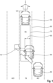
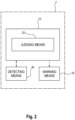
- FIG. 1 shows one embodiment of a vehicle or subject vehicle 50 according to the invention, which is provided with a driver assistance system 1 according to the invention which will be described in connection with FIG. 2 .
- the driver assistance system 1 provided in the subject vehicle 50 comprises a vehicle detection system 10 according to the invention, detecting means 40 and warning means 30.
- the detecting means 40 is for detecting a target vehicle 60 in a detection area DA located behind the subject vehicle 50, which will be described below.
- the detecting means 40 comprises radar sensors for detecting a target vehicle 60 in the detection area DA. These sensors may be part of a conventional (rear-) cross-traffic alert system, for example, and are capable of detecting at least a relative position of the target vehicle 60 with respect to the subject vehicle 50, a relative speed/ velocity of the target vehicle 60 with respect to the subject vehicle 50, respectively, in the x- and y-directions as shown in FIG. 1 .
- the x-direction shown in FIG. 1 corresponds to the longitudinal direction of the subject vehicle 50 and the target vehicle 60
- the y-direction shown in FIG. 1 corresponds to the transverse direction of the subject vehicle 50 and the target vehicle 60.
- the detecting means 40 comprises radar sensors for Rear Approaching Target Notification (RTAN) and for Long-range Rear Approaching Target Notification (L-RTAN).
- RTAN Rear Approaching Target Notification
- L-RTAN Long-range Rear Approaching Target Notification
- the judgement of the judging means may be based on either the L-RTAN radar detection or on RTAN radar detection or on both detections.
- the warning means 30 is for warning a driver of the subject vehicle 50 that a target vehicle 60 is present in the detection area DA.
- the warning means 30 may be a conventional visual or audible indicator (display or speaker) capable of notifying the driver of the subject vehicle 50 that the target vehicle 60 is present in the detection area DA and, for example, may fall below a safety distance from the subject vehicle 50.
- the vehicle detection system 10 can be formed by a computer or processor and is in particular for detecting a target vehicle 60 in the detection area DA located behind the subject vehicle 50.
- the detection area DA of the subject vehicle 50 ( Fig. 1 ) corresponds, in particular in the width or in the transverse direction, completely or to a certain extent to an area of the driving lane DL of the subject vehicle 50.
- the detection area DA may also comprise, completely or to a certain extent, the adjacent area or first adjacent lane ALF being located lateral/adjacent to the detection area DA or the driving lane DL and from which the target vehicle 60 starts for diagonally crossing the driving lane DL behind the subject vehicle 50.
- the detection area DA may also comprise, completely or to a certain extent, the adjacent area or second adjacent lane ALS being located lateral/adjacent to the detection area DA or the driving lane DL and opposite to the first adjacent lane ALF with respect to the driving lane DL.
- the target vehicle 60 moves to this second adjacent lane ALS while crossing the driving lane DL.
- the vehicle detection system 10 comprises judging means 20 for judging whether a target vehicle 60 which has been detected to enter the detection area DA is an alert object or not an alert object, and for outputting a result of judgement to the warning means 30.
- the target vehicle 60 occupies the detection area DA with a lateral overlap 65 of increasing size.
- the lateral overlap 65 is the distance in transverse or y-direction between a reference position or reference line 70 and a side part 75 of the target vehicle 60 which is within the driving lane DL and within the detection area DA and which is opposite to the reference line 70.
- This side part 75 of the target vehicle 60 is, for example, on the left side of the target vehicle 60 according to the representation in Fig. 1 .
- the reference line 70 is, for example, the sideline of the detection area DA or the sideline or transition line 80 of the driving lane DL to the first adjacent lane ALF, dependent of the size or width of the detection area DA.
- the lateral overlap 65 therefore corresponds to the proportion of the target vehicle's width with which the target vehicle 60 is actually in the detection area DA.
- the size of the lateral overlap 65 increases, in particular continuously. This change of size of the lateral overlap 65 is detected by the detecting means 40.
- the judging means 20 determines an overlap change rate on the basis of the changing lateral overlap 65 of the target vehicle 60 during lane change.
- the overlap change rate represents the change in size of the lateral overlap 65 over time, for example, over a specified time like a cycle time of a determination cycle.
- the determination of the overlap change rate is carried out in cycles with a cycle time of 0.05s, for example.
- the overlap change rate is defined as the difference between an actual lateral overlap and a previous lateral overlap divided by the cycle time.
- An overlap change rate warning threshold is set to be in the range of 1.0m/s to 1.5m/s and preferably 1.3m/s.
- the judging means 20 is configured to judge the target vehicle 60 to be not an alert object if the overlap change rate exceeds this overlap change rate warning threshold while the target vehicle 60 enters the detection area DA and keeps this value of the overlap change rate warning threshold. Otherwise, the judging means 20 judges the target vehicle 60 to be an alert object.
- the judging means 20 determines a lateral TTE (Time-to-Exit) of the target vehicle 60 for moving out of the detection area DA.
- TTE may be determined, for example, by calculating the ratio of lateral overlap of the target vehicle 60 to lateral velocity of the target vehicle 60 or may be evaluated in other ways, such as by simulation or experimentation.
- the judging means 20 further judges, in repeated determination cycles, whether TTE is lower than 4.0s or TTE is 4.0s or greater than 4.0s.
- TTE is lower than 4.0s a delay timer is set on a minimum value between TTE and 1.5s and the target vehicle 60 is judged to be not an alert object until the delay timer is expired. In this case, a warning signal is suppressed for a maximum of 1.5s before the delay timer is set again.
- the judging means 20 judges the target vehicle 60 to be an alert object.
- the judging means 20 is configured to judge the target vehicle 60 to be an alert object or to be not an alert object on the basis of the overlap change rate during lane change while crossing the driving lane DL.
- the warning means 30 warns the driver of the subject vehicle 50 that a target vehicle 60 is present in the detection area DA only if the judging means 20 judged the target vehicle 60 to be an alert object. In the other case, no warning is output. That is, the warning means 30 is configured to output a warning to the driver of the subject vehicle 50 that a target vehicle 60 is present in the detection area DA based on the judging means 20 judging the target vehicle 60 to be an alert object and to suppress output of a warning even if a target vehicle 60 is detected in the detection area DA by the detecting means 40 based on the judging means 20 judging the target vehicle 60 to be not an alert object.
Landscapes
- Engineering & Computer Science (AREA)
- Radar, Positioning & Navigation (AREA)
- Remote Sensing (AREA)
- Physics & Mathematics (AREA)
- General Physics & Mathematics (AREA)
- Computer Networks & Wireless Communication (AREA)
- Automation & Control Theory (AREA)
- Transportation (AREA)
- Mechanical Engineering (AREA)
- Data Mining & Analysis (AREA)
- Theoretical Computer Science (AREA)
- Computer Vision & Pattern Recognition (AREA)
- Electromagnetism (AREA)
- Life Sciences & Earth Sciences (AREA)
- Artificial Intelligence (AREA)
- Bioinformatics & Cheminformatics (AREA)
- Bioinformatics & Computational Biology (AREA)
- Evolutionary Biology (AREA)
- Evolutionary Computation (AREA)
- General Engineering & Computer Science (AREA)
- Human Computer Interaction (AREA)
- Mathematical Physics (AREA)
- Traffic Control Systems (AREA)
- Radar Systems Or Details Thereof (AREA)
Priority Applications (3)
| Application Number | Priority Date | Filing Date | Title |
|---|---|---|---|
| EP22202538.9A EP4357807A1 (fr) | 2022-10-19 | 2022-10-19 | Système de détection de véhicule et procédé de détection d'un véhicule cible dans une zone de détection située derrière un véhicule sujet |
| US18/482,381 US12573300B2 (en) | 2022-10-19 | 2023-10-06 | Vehicle detection system and method for detecting a target vehicle in a detection area located behind a subject vehicle |
| JP2023175376A JP7592816B2 (ja) | 2022-10-19 | 2023-10-10 | 自車両の後方に位置する検出エリアにおいてターゲット車両を検出するための車両検出システムおよび方法 |
Applications Claiming Priority (1)
| Application Number | Priority Date | Filing Date | Title |
|---|---|---|---|
| EP22202538.9A EP4357807A1 (fr) | 2022-10-19 | 2022-10-19 | Système de détection de véhicule et procédé de détection d'un véhicule cible dans une zone de détection située derrière un véhicule sujet |
Publications (1)
| Publication Number | Publication Date |
|---|---|
| EP4357807A1 true EP4357807A1 (fr) | 2024-04-24 |
Family
ID=83900128
Family Applications (1)
| Application Number | Title | Priority Date | Filing Date |
|---|---|---|---|
| EP22202538.9A Pending EP4357807A1 (fr) | 2022-10-19 | 2022-10-19 | Système de détection de véhicule et procédé de détection d'un véhicule cible dans une zone de détection située derrière un véhicule sujet |
Country Status (3)
| Country | Link |
|---|---|
| US (1) | US12573300B2 (fr) |
| EP (1) | EP4357807A1 (fr) |
| JP (1) | JP7592816B2 (fr) |
Families Citing this family (1)
| Publication number | Priority date | Publication date | Assignee | Title |
|---|---|---|---|---|
| CN114348001B (zh) * | 2022-01-06 | 2024-04-26 | 腾讯科技(深圳)有限公司 | 一种交通仿真方法、装置、设备以及存储介质 |
Citations (2)
| Publication number | Priority date | Publication date | Assignee | Title |
|---|---|---|---|---|
| CN110435650A (zh) * | 2019-08-22 | 2019-11-12 | 爱驰汽车有限公司 | 车辆后碰撞紧急避让方法、系统、设备及存储介质 |
| US11027653B2 (en) * | 2019-01-28 | 2021-06-08 | Mando Corporation | Apparatus, system and method for preventing collision |
Family Cites Families (14)
| Publication number | Priority date | Publication date | Assignee | Title |
|---|---|---|---|---|
| KR101704524B1 (ko) * | 2015-09-02 | 2017-02-08 | 현대자동차주식회사 | 차량 및 그 제어방법 |
| JP6520783B2 (ja) * | 2016-03-22 | 2019-05-29 | 株式会社デンソー | 車両検知装置 |
| US10836376B2 (en) * | 2016-09-06 | 2020-11-17 | Magna Electronics Inc. | Vehicle sensing system with enhanced detection of vehicle angle |
| JP6983915B2 (ja) | 2017-06-12 | 2021-12-17 | コンチネンタル オートモーティブ ゲゼルシャフト ミット ベシュレンクテル ハフツング | 後方プリクラッシュセーフティシステム |
| WO2019116458A1 (fr) * | 2017-12-13 | 2019-06-20 | 本田技研工業株式会社 | Véhicule, et système et procédé de commande associés |
| JP6955214B2 (ja) | 2017-12-27 | 2021-10-27 | トヨタ自動車株式会社 | 内燃機関の制御装置 |
| JP2019174320A (ja) | 2018-03-29 | 2019-10-10 | トヨタ自動車株式会社 | 車両認識装置 |
| JP7192585B2 (ja) | 2019-03-12 | 2022-12-20 | トヨタ自動車株式会社 | 運転支援装置 |
| JP7424760B2 (ja) * | 2019-06-12 | 2024-01-30 | 株式会社Subaru | 車両制御装置 |
| US11561548B2 (en) * | 2020-09-11 | 2023-01-24 | Uatc, Llc | Systems and methods for generating basis paths for autonomous vehicle motion control |
| EP4397553B1 (fr) * | 2021-09-01 | 2026-02-18 | Nissan Motor Co., Ltd. | Procédé de commande de véhicule et dispositif de commande de véhicule |
| WO2023073773A1 (fr) * | 2021-10-25 | 2023-05-04 | 株式会社Subaru | Dispositif de commande de déplacement |
| US12084052B2 (en) * | 2022-04-06 | 2024-09-10 | GM Global Technology Operations LLC | System and method of predicting and displaying a side blind zone entry alert |
| JP2024025280A (ja) * | 2022-08-12 | 2024-02-26 | キヤノン株式会社 | 制御装置、制御システム、制御方法、およびプログラム |
-
2022
- 2022-10-19 EP EP22202538.9A patent/EP4357807A1/fr active Pending
-
2023
- 2023-10-06 US US18/482,381 patent/US12573300B2/en active Active
- 2023-10-10 JP JP2023175376A patent/JP7592816B2/ja active Active
Patent Citations (2)
| Publication number | Priority date | Publication date | Assignee | Title |
|---|---|---|---|---|
| US11027653B2 (en) * | 2019-01-28 | 2021-06-08 | Mando Corporation | Apparatus, system and method for preventing collision |
| CN110435650A (zh) * | 2019-08-22 | 2019-11-12 | 爱驰汽车有限公司 | 车辆后碰撞紧急避让方法、系统、设备及存储介质 |
Also Published As
| Publication number | Publication date |
|---|---|
| US20240135822A1 (en) | 2024-04-25 |
| JP2024060586A (ja) | 2024-05-02 |
| JP7592816B2 (ja) | 2024-12-02 |
| US20240233547A9 (en) | 2024-07-11 |
| US12573300B2 (en) | 2026-03-10 |
Similar Documents
| Publication | Publication Date | Title |
|---|---|---|
| JP6017044B2 (ja) | ドライバーアシストシステム及びドライバーアシストシステムの作動方法 | |
| CN101678819B (zh) | 碰撞减轻装置 | |
| KR102005253B1 (ko) | 극도로 빠르게 접근하는 차량들에 응답하는 차선 보조 시스템 | |
| JP7464748B2 (ja) | 外界認識装置、および、外界認識方法 | |
| EP4046884B1 (fr) | Appareil d'assistance d'évitement de collision | |
| EP2571004A1 (fr) | Système permettant de déduire une intention de changement de voie d'un conducteur | |
| JP5163991B2 (ja) | 複雑な交通状況における車両の速度制御方法 | |
| EP3000104B1 (fr) | Systemes d'attenuation de collision ayant une largeur de declencheur reglable | |
| JP2010102641A (ja) | 車両用衝突回避装置 | |
| JP2015505285A (ja) | 交通をモニタリングするための方法及び制御ユニット | |
| US12573300B2 (en) | Vehicle detection system and method for detecting a target vehicle in a detection area located behind a subject vehicle | |
| JP6548147B2 (ja) | 車両用制御装置 | |
| US12570322B2 (en) | Vehicle detection system and method for detecting a target vehicle in a detection area located behind a subject vehicle | |
| JP7631467B2 (ja) | 自車両の後方に位置する検出エリアにおいて対象物を検出するための車両物体検出システムおよび方法 | |
| EP4358065A1 (fr) | Système de détection d'objet de véhicule et procédé de détection d'un objet cible dans une zone de détection située derrière et latéralement d'un véhicule sujet | |
| US12576782B2 (en) | Vehicle object detection system and method for detecting a target object in a detection area located behind a subject vehicle | |
| JP2023152108A (ja) | 車両衝突回避装置 | |
| CN117048601A (zh) | 用于控制碰撞预警操作的方法、系统和计算机程序产品 |
Legal Events
| Date | Code | Title | Description |
|---|---|---|---|
| PUAI | Public reference made under article 153(3) epc to a published international application that has entered the european phase |
Free format text: ORIGINAL CODE: 0009012 |
|
| STAA | Information on the status of an ep patent application or granted ep patent |
Free format text: STATUS: THE APPLICATION HAS BEEN PUBLISHED |
|
| AK | Designated contracting states |
Kind code of ref document: A1 Designated state(s): AL AT BE BG CH CY CZ DE DK EE ES FI FR GB GR HR HU IE IS IT LI LT LU LV MC ME MK MT NL NO PL PT RO RS SE SI SK SM TR |
|
| STAA | Information on the status of an ep patent application or granted ep patent |
Free format text: STATUS: REQUEST FOR EXAMINATION WAS MADE |
|
| 17P | Request for examination filed |
Effective date: 20241024 |
|
| RBV | Designated contracting states (corrected) |
Designated state(s): AL AT BE BG CH CY CZ DE DK EE ES FI FR GB GR HR HU IE IS IT LI LT LU LV MC ME MK MT NL NO PL PT RO RS SE SI SK SM TR |
|
| RAP3 | Party data changed (applicant data changed or rights of an application transferred) |
Owner name: AUMOVIO AUTONOMOUS MOBILITY GERMANY GMBH Owner name: TOYOTA JIDOSHA KABUSHIKI KAISHA |
|
| REG | Reference to a national code |
Ref country code: DE Ref legal event code: R079 Free format text: PREVIOUS MAIN CLASS: G01S0007410000 Ipc: G01S0013931000 |
|
| GRAP | Despatch of communication of intention to grant a patent |
Free format text: ORIGINAL CODE: EPIDOSNIGR1 |
|
| STAA | Information on the status of an ep patent application or granted ep patent |
Free format text: STATUS: GRANT OF PATENT IS INTENDED |
|
| RIC1 | Information provided on ipc code assigned before grant |
Ipc: G01S 13/931 20200101AFI20260114BHEP Ipc: G01S 7/41 20060101ALI20260114BHEP Ipc: G01S 13/72 20060101ALI20260114BHEP Ipc: G01S 13/58 20060101ALI20260114BHEP Ipc: G08G 1/16 20060101ALI20260114BHEP Ipc: B60W 40/04 20060101ALI20260114BHEP Ipc: B60W 50/14 20200101ALI20260114BHEP Ipc: B60W 30/095 20120101ALI20260114BHEP Ipc: G06F 18/213 20230101ALI20260114BHEP |
|
| INTG | Intention to grant announced |
Effective date: 20260123 |