EP4357809A1 - Procédé d'étalonnage de position d'une caméra et d'un capteur lidar doté d'un panneau d'étalonnage et système d'étalonnage de position - Google Patents
Procédé d'étalonnage de position d'une caméra et d'un capteur lidar doté d'un panneau d'étalonnage et système d'étalonnage de position Download PDFInfo
- Publication number
- EP4357809A1 EP4357809A1 EP23203375.3A EP23203375A EP4357809A1 EP 4357809 A1 EP4357809 A1 EP 4357809A1 EP 23203375 A EP23203375 A EP 23203375A EP 4357809 A1 EP4357809 A1 EP 4357809A1
- Authority
- EP
- European Patent Office
- Prior art keywords
- camera
- calibration
- lidar sensor
- image
- calibration board
- Prior art date
- Legal status (The legal status is an assumption and is not a legal conclusion. Google has not performed a legal analysis and makes no representation as to the accuracy of the status listed.)
- Granted
Links
Images


Classifications
-
- B—PERFORMING OPERATIONS; TRANSPORTING
- B60—VEHICLES IN GENERAL
- B60W—CONJOINT CONTROL OF VEHICLE SUB-UNITS OF DIFFERENT TYPE OR DIFFERENT FUNCTION; CONTROL SYSTEMS SPECIALLY ADAPTED FOR HYBRID VEHICLES; ROAD VEHICLE DRIVE CONTROL SYSTEMS FOR PURPOSES NOT RELATED TO THE CONTROL OF A PARTICULAR SUB-UNIT
- B60W10/00—Conjoint control of vehicle sub-units of different type or different function
- B60W10/18—Conjoint control of vehicle sub-units of different type or different function including control of braking systems
-
- B—PERFORMING OPERATIONS; TRANSPORTING
- B60—VEHICLES IN GENERAL
- B60W—CONJOINT CONTROL OF VEHICLE SUB-UNITS OF DIFFERENT TYPE OR DIFFERENT FUNCTION; CONTROL SYSTEMS SPECIALLY ADAPTED FOR HYBRID VEHICLES; ROAD VEHICLE DRIVE CONTROL SYSTEMS FOR PURPOSES NOT RELATED TO THE CONTROL OF A PARTICULAR SUB-UNIT
- B60W10/00—Conjoint control of vehicle sub-units of different type or different function
- B60W10/20—Conjoint control of vehicle sub-units of different type or different function including control of steering systems
-
- B—PERFORMING OPERATIONS; TRANSPORTING
- B60—VEHICLES IN GENERAL
- B60W—CONJOINT CONTROL OF VEHICLE SUB-UNITS OF DIFFERENT TYPE OR DIFFERENT FUNCTION; CONTROL SYSTEMS SPECIALLY ADAPTED FOR HYBRID VEHICLES; ROAD VEHICLE DRIVE CONTROL SYSTEMS FOR PURPOSES NOT RELATED TO THE CONTROL OF A PARTICULAR SUB-UNIT
- B60W30/00—Purposes of road vehicle drive control systems not related to the control of a particular sub-unit, e.g. of systems using conjoint control of vehicle sub-units
- B60W30/08—Active safety systems predicting or avoiding probable or impending collision or attempting to minimise its consequences
- B60W30/095—Predicting travel path or likelihood of collision
- B60W30/0956—Predicting travel path or likelihood of collision the prediction being responsive to traffic or environmental parameters
-
- B—PERFORMING OPERATIONS; TRANSPORTING
- B60—VEHICLES IN GENERAL
- B60W—CONJOINT CONTROL OF VEHICLE SUB-UNITS OF DIFFERENT TYPE OR DIFFERENT FUNCTION; CONTROL SYSTEMS SPECIALLY ADAPTED FOR HYBRID VEHICLES; ROAD VEHICLE DRIVE CONTROL SYSTEMS FOR PURPOSES NOT RELATED TO THE CONTROL OF A PARTICULAR SUB-UNIT
- B60W50/00—Details of control systems for road vehicle drive control not related to the control of a particular sub-unit, e.g. process diagnostic or vehicle driver interfaces
- B60W50/08—Interaction between the driver and the control system
- B60W50/14—Means for informing the driver, warning the driver or prompting a driver intervention
-
- B—PERFORMING OPERATIONS; TRANSPORTING
- B60—VEHICLES IN GENERAL
- B60W—CONJOINT CONTROL OF VEHICLE SUB-UNITS OF DIFFERENT TYPE OR DIFFERENT FUNCTION; CONTROL SYSTEMS SPECIALLY ADAPTED FOR HYBRID VEHICLES; ROAD VEHICLE DRIVE CONTROL SYSTEMS FOR PURPOSES NOT RELATED TO THE CONTROL OF A PARTICULAR SUB-UNIT
- B60W60/00—Drive control systems specially adapted for autonomous road vehicles
- B60W60/001—Planning or execution of driving tasks
- B60W60/0015—Planning or execution of driving tasks specially adapted for safety
-
- G—PHYSICS
- G01—MEASURING; TESTING
- G01S—RADIO DIRECTION-FINDING; RADIO NAVIGATION; DETERMINING DISTANCE OR VELOCITY BY USE OF RADIO WAVES; LOCATING OR PRESENCE-DETECTING BY USE OF THE REFLECTION OR RERADIATION OF RADIO WAVES; ANALOGOUS ARRANGEMENTS USING OTHER WAVES
- G01S17/00—Systems using the reflection or reradiation of electromagnetic waves other than radio waves, e.g. lidar systems
- G01S17/86—Combinations of lidar systems with systems other than lidar, radar or sonar, e.g. with direction finders
-
- G—PHYSICS
- G01—MEASURING; TESTING
- G01S—RADIO DIRECTION-FINDING; RADIO NAVIGATION; DETERMINING DISTANCE OR VELOCITY BY USE OF RADIO WAVES; LOCATING OR PRESENCE-DETECTING BY USE OF THE REFLECTION OR RERADIATION OF RADIO WAVES; ANALOGOUS ARRANGEMENTS USING OTHER WAVES
- G01S17/00—Systems using the reflection or reradiation of electromagnetic waves other than radio waves, e.g. lidar systems
- G01S17/87—Combinations of systems using electromagnetic waves other than radio waves
-
- G—PHYSICS
- G01—MEASURING; TESTING
- G01S—RADIO DIRECTION-FINDING; RADIO NAVIGATION; DETERMINING DISTANCE OR VELOCITY BY USE OF RADIO WAVES; LOCATING OR PRESENCE-DETECTING BY USE OF THE REFLECTION OR RERADIATION OF RADIO WAVES; ANALOGOUS ARRANGEMENTS USING OTHER WAVES
- G01S17/00—Systems using the reflection or reradiation of electromagnetic waves other than radio waves, e.g. lidar systems
- G01S17/88—Lidar systems specially adapted for specific applications
- G01S17/93—Lidar systems specially adapted for specific applications for anti-collision purposes
- G01S17/931—Lidar systems specially adapted for specific applications for anti-collision purposes of land vehicles
-
- G—PHYSICS
- G01—MEASURING; TESTING
- G01S—RADIO DIRECTION-FINDING; RADIO NAVIGATION; DETERMINING DISTANCE OR VELOCITY BY USE OF RADIO WAVES; LOCATING OR PRESENCE-DETECTING BY USE OF THE REFLECTION OR RERADIATION OF RADIO WAVES; ANALOGOUS ARRANGEMENTS USING OTHER WAVES
- G01S7/00—Details of systems according to groups G01S13/00, G01S15/00, G01S17/00
- G01S7/48—Details of systems according to groups G01S13/00, G01S15/00, G01S17/00 of systems according to group G01S17/00
- G01S7/497—Means for monitoring or calibrating
- G01S7/4972—Alignment of sensor
-
- G—PHYSICS
- G06—COMPUTING OR CALCULATING; COUNTING
- G06T—IMAGE DATA PROCESSING OR GENERATION, IN GENERAL
- G06T7/00—Image analysis
- G06T7/80—Analysis of captured images to determine intrinsic or extrinsic camera parameters, i.e. camera calibration
-
- B—PERFORMING OPERATIONS; TRANSPORTING
- B60—VEHICLES IN GENERAL
- B60W—CONJOINT CONTROL OF VEHICLE SUB-UNITS OF DIFFERENT TYPE OR DIFFERENT FUNCTION; CONTROL SYSTEMS SPECIALLY ADAPTED FOR HYBRID VEHICLES; ROAD VEHICLE DRIVE CONTROL SYSTEMS FOR PURPOSES NOT RELATED TO THE CONTROL OF A PARTICULAR SUB-UNIT
- B60W2300/00—Indexing codes relating to the type of vehicle
- B60W2300/12—Trucks; Load vehicles
- B60W2300/121—Fork lift trucks, Clarks
-
- B—PERFORMING OPERATIONS; TRANSPORTING
- B60—VEHICLES IN GENERAL
- B60W—CONJOINT CONTROL OF VEHICLE SUB-UNITS OF DIFFERENT TYPE OR DIFFERENT FUNCTION; CONTROL SYSTEMS SPECIALLY ADAPTED FOR HYBRID VEHICLES; ROAD VEHICLE DRIVE CONTROL SYSTEMS FOR PURPOSES NOT RELATED TO THE CONTROL OF A PARTICULAR SUB-UNIT
- B60W2420/00—Indexing codes relating to the type of sensors based on the principle of their operation
- B60W2420/40—Photo, light or radio wave sensitive means, e.g. infrared sensors
- B60W2420/403—Image sensing, e.g. optical camera
-
- B—PERFORMING OPERATIONS; TRANSPORTING
- B60—VEHICLES IN GENERAL
- B60W—CONJOINT CONTROL OF VEHICLE SUB-UNITS OF DIFFERENT TYPE OR DIFFERENT FUNCTION; CONTROL SYSTEMS SPECIALLY ADAPTED FOR HYBRID VEHICLES; ROAD VEHICLE DRIVE CONTROL SYSTEMS FOR PURPOSES NOT RELATED TO THE CONTROL OF A PARTICULAR SUB-UNIT
- B60W2420/00—Indexing codes relating to the type of sensors based on the principle of their operation
- B60W2420/40—Photo, light or radio wave sensitive means, e.g. infrared sensors
- B60W2420/408—Radar; Laser, e.g. lidar
-
- G—PHYSICS
- G06—COMPUTING OR CALCULATING; COUNTING
- G06T—IMAGE DATA PROCESSING OR GENERATION, IN GENERAL
- G06T2207/00—Indexing scheme for image analysis or image enhancement
- G06T2207/10—Image acquisition modality
- G06T2207/10028—Range image; Depth image; 3D point clouds
-
- G—PHYSICS
- G06—COMPUTING OR CALCULATING; COUNTING
- G06T—IMAGE DATA PROCESSING OR GENERATION, IN GENERAL
- G06T2207/00—Indexing scheme for image analysis or image enhancement
- G06T2207/30—Subject of image; Context of image processing
- G06T2207/30244—Camera pose
-
- G—PHYSICS
- G06—COMPUTING OR CALCULATING; COUNTING
- G06T—IMAGE DATA PROCESSING OR GENERATION, IN GENERAL
- G06T2207/00—Indexing scheme for image analysis or image enhancement
- G06T2207/30—Subject of image; Context of image processing
- G06T2207/30248—Vehicle exterior or interior
- G06T2207/30252—Vehicle exterior; Vicinity of vehicle
Definitions
- the invention relates to a method for position calibration of a camera and a lidar sensor with a calibration board, as well as a position calibration system for position calibration of the camera and the lidar sensor.
- various types of obstacle detection systems are used in autonomous vehicles to detect obstacles.
- video cameras and lidar sensors are used to detect obstacles.
- the images generated by the obstacle detection systems are preferably evaluated together. It is important to know where a detected obstacle is located in an image taken by one obstacle detection system and in another image taken by the other obstacle detection system. The results of the obstacle detection systems should be able to be merged.
- mechanical tolerances when installing the obstacle detection systems are problematic.
- a small error in the alignment of the lidar sensor causes a large deviation at a distance of just 50 m.
- a detected obstacle in the image of the lidar sensor is suddenly in a completely different place.
- a detected collision is suddenly no longer a collision, and an obstacle detected outside the roadway can suddenly become a dangerous situation.
- the method according to the invention for position calibration of a camera and a lidar sensor using a calibration board is described below.
- the calibration board comprises known patterns. These known patterns have different brightnesses.
- the known pattern preferably comprises the colors black and white.
- additional reflection areas are applied to the calibration board, which have a higher reflectivity than the known patterns of different brightnesses. Reflectivity is the ratio between reflected and incident intensity as an energy quantity, for example in electromagnetic waves (luminous flux).
- a first process step at least one image of the calibration board is taken with the camera.
- the pose of the calibration board relative to the camera is determined based on the known patterns of different brightness.
- the term “pose” refers to the position and orientation of the calibration board, particularly in the camera coordinate system.
- a laser light is emitted from the lidar sensor onto the calibration board.
- a third process step at least one image is taken with the lidar sensor and the areas with high reflectivity are determined based on intensity values of the laser light reflected from the calibration panel.
- the pose of the calibration board relative to the lidar sensor is determined based on the known reflection areas and the identified areas with high reflectivity.
- the image with the camera and the image with the lidar sensor can be recorded in parallel.
- the process steps therefore do not represent a mandatory chronological sequence.
- the laser light must be emitted by the lidar sensor first before the pose of the calibration board relative to the lidar sensor can be determined.
- the pose of the calibration board relative to the camera can be determined in parallel.
- both images can then be converted into a common coordinate system (GCS) based on the determined poses.
- GCS common coordinate system
- the images taken by the camera and the lidar sensor are converted into a common coordinate system (GCS).
- an image taken by one sensor is converted into the coordinate system of the other image taken by the other sensor based on the determined poses.
- the image taken by the camera can be converted into the coordinate system of the image taken by the lidar sensor.
- a transformation takes place from the camera coordinate system (KKS) to the lidar coordinate system (LKS).
- the image taken by the lidar sensor can of course also be converted into the coordinate system of the image taken by the camera.
- a transformation takes place from the lidar coordinate system (LKS) to the camera coordinate system (KKS).
- conversion values are determined based on the determined poses in order to convert future images into a common coordinate system (GCS), or to convert a future image from one sensor into the coordinate system of the other image and thus of the other sensor.
- GCS common coordinate system
- a future image of the camera can be converted from the camera coordinate system (CCS) to the lidar coordinate system (LCS) using conversion values.
- a future image of the lidar sensor can be converted from the lidar coordinate system (LCS) to the camera coordinate system (CCS) using conversion values.
- a single calibration board can be used to determine the poses of the calibration board relative to the camera and relative to the lidar sensor. This makes it possible to convert images taken by the camera and/or the lidar sensor into the other coordinate system. If an object is detected in a camera image, it can be said immediately at which position in the lidar sensor image this object must be. The same applies to an object in the lidar sensor image. It can be said immediately at which position in the camera image this object must be.
- the calibration board can also simply comprise a painted wall.
- the calibration board is therefore not necessarily a separate structure that is set up in the room or hung on a wall.
- the position of objects in space can be determined. Additional properties can be determined from the camera images using object recognition or code and text reading. For example, it is possible to distinguish whether the object in the image is a person or not. Clear identification via a QR code is also possible. This could lead to more efficient anti-collision solutions, e.g. a person has to be driven around more slowly and carefully than a pallet. In addition or alternatively, documentation can be carried out for palletizing tasks, for example by simultaneously identifying goods loaded by an automated guided vehicle. Furthermore, an improvement in object detection can be achieved with anti-collision solutions. In the image of the lidar sensor, i.e.
- a small object e.g. a fork of a forklift
- the camera images i.e. the camera data
- the camera and the lidar sensor are arranged in a fixed position relative to one another. This means that the distance and alignment between the camera and the lidar sensor remain the same, i.e. constant. Nevertheless, it is possible for the camera and lidar sensor to be moved together. For example, they can be attached together to a vehicle that is moved autonomously. The distance and alignment of the camera and the lidar sensor to one another then corresponds to the distance and alignment between the camera and the lidar sensor during later operation.
- the camera and the lidar sensor record the respective image simultaneously. This means that the same scene is recorded.
- a time offset between the recording of the different images is preferably less than 1 second, 500 ms, 200 ms, 100 ms, 50 ms, 20 ms, 10 ms or less than 1 ms.
- the respective image of the camera and the lidar sensor have a time stamp, whereby time information from the time stamp can be used to say which images were taken by the lidar sensor and camera "simultaneously".
- the smallest possible time offset is achieved by synchronizing local timers of the lidar sensor and camera with an external timer or by making the time signal of an external timer available directly to the lidar sensor and the camera. By sorting the images of the lidar sensor and the camera based on their time stamps, the smallest possible time offset can then be achieved.
- the additional reflection areas comprise reflection strips. These are preferably glued to the calibration board.
- the additional reflection areas in particular in the form of the reflection strips, are aligned at an angle to one another.
- the reflection areas are not all aligned parallel to one another because otherwise it would not be possible to clearly identify the pose between the calibration board and the lidar sensor using laser lines that the lidar sensor emits in the form of laser light.
- the known patterns include ChArUco patterns.
- Such patterns can be used for both intrinsic calibration, such as estimating and correcting the lens distortion, focal length and/or focal point of the camera, and extrinsic calibration, such as determining the pose of the calibration board in the camera coordinate system.
- This method was developed, for example, by Garrido-Jurado, S., Mu-Salinas, R., Madrid-Cuevas, F., and Mar Jim z, M. (2014). "Automatic generation and detection of highly reliable fiducial markers under occlusion.” Pattern Recogn. 47, 6 (June 2014), 2280-2292 described.
- the open source library “opencv camera calibration (2022)” can be used for this. Opencv camera calibration (2022).
- Opencv camera calibration (2022). “Camera calibration with opencv, ⁇ https://docs.opencv.org/4.x/d4/d94/tutorial_camera_calibration.html>.
- the intrinsic camera calibration is determined directly from the camera recordings. This makes it much easier to use in practice, as the camera does not have to be calibrated beforehand. This means that cameras from other manufacturers can easily be introduced into the process, for example.
- a camera calibration that has to be carried out in advance always carries the risk that the optical properties of the camera system have changed in the period between the intrinsic calibration of the camera and the registration of the lidar sensor against the camera (e.g. due to vibration, focus adjustment and thermal expansion). Since the calibration board is small compared to the size of typical measuring rooms, the calibration board could also remain permanently in the measuring room in order to regularly check the measurement parameters by re-recording the calibration board with the lidar sensor and camera (quality assurance).
- a single calibration board is used to determine all calibration steps (camera: intrinsic and extrinsic, lidar sensor: extrinsic). This creates a direct link between the laser-related measurement areas (reflection areas) and the camera-related measurement areas (ChArUco pattern) directly via the calibration board. This increases the robustness of the method and avoids setup errors compared to other methods in which intrinsic and extrinsic calibration are carried out separately.
- the spatially compact design of the calibration board is suitable for use in industrial environments where the available space may be limited or some areas are difficult to access, making it impossible to set up complex calibration devices.
- the known patterns are localized on the calibration board in one step.
- the intrinsic parameters of the camera in particular focal length, focal point and/or lens distortion, are determined using the known patterns.
- the camera is then calibrated using the intrinsic parameters. The camera therefore does not have to be calibrated beforehand. This makes it much easier to use in practice.
- a large number of images are used to determine the intrinsic parameters of the camera. In this case, those images are discarded in which the projection error exceeds a threshold value.
- the camera takes pictures of the same scene.
- the relative position between the camera and the calibration board is preferably unchanged. Nevertheless, it is also conceivable that the position or orientation of the calibration board and/or the camera has changed in at least two of the images or in all of the images. Preferably, a certain number of images are also taken with the camera, this number being above a further threshold value. Further preferably, at least 2, 3, 6, 8, 12, 16, 20 or more than 25 images are used.
- the calibration board is placed in such a way that it is completely in the camera image and that it is crossed by a large number of laser lines, i.e. scan lines of the lidar sensor.
- the method is not limited to a lidar sensor that generates a certain number of laser lines, such as 4. It therefore also allows the use of lidar sensors with various point distribution characteristics, such as single-plane lidar sensors, or lidar sensors with pseudo-random point distributions.
- the lidar sensor In a further development of the method for position calibration, the lidar sensor generates more than 2, 3, 4 or more than 5 laser lines. These laser lines preferably run parallel to each other and are preferably generated simultaneously. This makes it possible to determine the pose, i.e. the position and alignment of the calibration board to the lidar sensor, very precisely, because different laser lines cross different reflection areas. In particular, if the reflection areas are aligned at an angle to each other, the pose of the calibration board relative to the lidar sensor can be determined very precisely.
- a curvature of the laser lines is compensated by a known or calculated deviation from a straight laser line.
- the laser line that the lidar sensor projects onto the calibration board is, strictly speaking, not a straight line, but a flatly curved hyperbola.
- the deviation from a straight line is not too great, but it is still possible to take the curvature of the hyperbola into account. This can be achieved, among other things, by taking the deviation from a straight laser line from a look-up table.
- the look-up table is calculated and saved once for each laser line.
- a step is used to determine which sections of the reflected laser lines have an intensity profile that is above a threshold value and which sections of the reflected laser lines lie in one plane. Sections above the threshold value are areas with high reflectivity. This is how a binarization of the intensity profile is carried out. All additional reflection areas on the calibration board lie in one plane. Such an image must also result from the reflected laser lines. Points in space are determined for the reflected laser lines (e.g. X, Y, Z) and a corresponding intensity value is determined for each point. Furthermore, the reflectivity of the additional reflection areas are higher than the surroundings. In a further process step, the sections determined in this way are compared with the known additional reflection areas. It is known, or it has been determined from at least one image from the camera, where the additional reflection areas are located on the calibration board. This allows the calibration board to be discovered in the image from the lidar sensor.
- the adjustment takes place by determining a displacement and a rotation angle of the determined sections relative to the origin of the calibration table in order to determine the pose of the calibration table relative to the lidar sensor.
- the reflected laser lines can be shifted in the plane until the areas of the reflected laser lines whose intensity values are above a threshold value correspond to the areas on the calibration table where the additional reflection areas are arranged. This can be done using an iterative process in which the reflected laser lines are also rotated.
- data from at least one radar sensor could also be included.
- the calibration panel could also include radar reflectors. These radar reflectors can be active or passive radar reflectors.
- the camera and/or the lidar sensor are arranged in a fixed position.
- the position and the alignment between the camera and the lidar sensor are also fixed and are not changed.
- the calibration board can be moved while different images are taken by the camera and the lidar sensor.
- the calibration board can be arranged in a fixed position. In this case, a combination of camera and lidar sensor, whereby the position and alignment between camera and lidar sensor remains unchanged. As a result, the alignment between calibration board and camera / lidar sensor differs in the individual images.
- test calibration boards can be set up.
- the position calibration can be checked using these test calibration boards.
- the lidar sensor can comprise an azimuth detection field of more than 120°, 180° or more than 240°.
- the azimuth detection field can also be 360°.
- at least one further camera and at least one further calibration board are used. More than one additional camera could also be used. In this case, all cameras could be compared against the lidar sensor. The method would then allow all images to be converted into a common coordinate system based on the determined poses. It would also be conceivable that the images from at least two but not all sensors would be converted into the coordinate system of the remaining sensor (e.g. the lidar sensor). In principle, it would also be possible that in this case conversion values could also be determined in order to convert future images into a common coordinate system. It would also be possible that conversion values could be determined in order to convert a future image into the coordinate system of another future image from another sensor.
- the pose of the calibration board relative to the lidar sensor could also be optimized using additional prior knowledge.
- a Monte Carlo search can be used to determine the desired pose.
- the search space can then be optimized based on the pose of the calibration board relative to the lidar sensor determined during the extrinsic camera calibration.
- Camera can be significantly restricted. This is based on the assumption that the lidar sensor and camera are close to each other, or that their position relative to each other is roughly known. However, this is not a mandatory restriction and merely reduces the search effort in the parameter space.
- the remaining free parameters are essentially limited to the angle of deviation from the horizontal of at least one laser line that sweeps over the calibration board and its height on the calibration board.
- a distance measure is then used as an optimization criterion, such as the Hamming distance, which indicates the distance between the recorded intensity values of the reflected laser light that are above a threshold value and the position of the additional reflection areas predicted using the current transformation.
- a position and/or the alignment of the calibration board relative to a combination of camera and lidar sensor can be changed.
- the calibration board is preferably moved around the combination of camera and lidar sensor.
- the combination of camera and lidar sensor could also be moved around the calibration board.
- the distance and alignment between the camera and lidar sensor remains unchanged.
- the camera and lidar sensor then take pictures again and the pose of the calibration board relative to the camera and lidar sensor is determined again. This makes it possible, for example, to determine more precise conversion values.
- the position calibration system comprises a camera, a lidar sensor, a calibration board and a processing unit.
- the calibration board has known patterns, wherein the known patterns comprise different brightnesses. Additional reflection areas are applied to the calibration board, which have a higher reflectivity than the known patterns of different brightnesses.
- the camera is designed to take an image of the calibration board, wherein the processing unit is designed to determine a pose of the calibration board relative to the camera based on the known patterns. This known patterns are recorded in the camera image.
- the lidar sensor is designed to emit a laser light onto the calibration board.
- the lidar sensor is further designed to take an image, wherein the processing unit is designed to determine areas with high reflectivity based on intensity values of the laser light reflected from the calibration board.
- the processing unit is designed to convert both images into a common coordinate system (GKS) based on the determined poses.
- the processing unit is designed to convert one image into the coordinate system of the other image based on the determined poses.
- the processing unit is designed to determine conversion values based on the determined poses in order to convert future images into a common coordinate system (GKS) or to convert a future image from one sensor (camera or lidar sensor) into the coordinate system of another future image from the other sensor (lidar sensor or camera). Provision can be made to transform the lidar data into a 2D image coordinate system. Also, the position of at least some pixels in the 2D image coordinate system could be transformed into the 3D system.
- an autonomously driving vehicle in particular in the form of a forklift truck, is specified.
- the autonomously driving vehicle comprises a camera, a lidar sensor and a processing unit.
- the camera and the lidar sensor are calibrated to one another according to one of the preceding claims and are arranged on the vehicle so that they are relatively immovable to one another.
- the lidar sensor is designed to continuously monitor the roadway, in particular in front of the vehicle, for obstacles.
- the processing unit is designed to compare at least one object in the data (images) of the lidar sensor, which is e.g.
- the warning can be visual and/or acoustic and/or haptic, e.g. through vibrations.
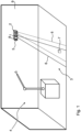
- FIG. 1 shows the use of a camera 1 and a lidar sensor 2, which together monitor a spatial area 3 of a production environment.
- a robot 4 is shown in the production environment.
- the spatial area 3 in which the robot 4 is located is monitored with the camera 1 and the lidar sensor 2.
- the camera 1 and the lidar sensor 2 are arranged in a common housing 5. However, they can also be housed in different housings.
- Both the camera 1 and the lidar sensor 2 have a monitoring field 6.
- the monitoring field 6 of the camera 1 is shown with a solid line
- the monitoring field 6 of the lidar sensor 2 is shown with a dotted line. Both monitoring fields 6 are aligned so that they overlap one another, at least partially.
- the data from camera 1 and the data from lidar sensor 2 can be fused so that it can be said immediately where a detected object 7 in the data from camera 1 must appear in the data from lidar sensor 2 and vice versa.
- This fusion can be carried out using a processing unit 8, which is arranged, for example, in the common housing 5.
- the common housing 5 is attached to a wall 9.
- Camera 1 can be a photo camera or a video camera.
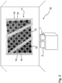
- a position calibration system 10 is shown with the camera 1, the lidar sensor 2 and a calibration board 11.
- the calibration board 11 comprises known patterns 12 of different brightness.
- the known patterns 12 are preferably ChArUco patterns. These comprise a checkerboard structure with ArUco patterns.
- the patterns 12 themselves are known in terms of size and orientation to one another.
- the camera 1 and the lidar sensor 2 are fixed in position, i.e. cannot be moved relative to each other. This arrangement is retained after position calibration, i.e. when used in an autonomously driving vehicle.
- the camera 1 takes an image 13 in which the calibration board 11 is located.
- the processing unit 8 it is possible to determine a pose of the calibration board 11 relative to the camera 1. This is done by detecting the known patterns 12.
- the determination of the pose (position and orientation) of the calibration board 11 relative to the camera 1 is also referred to as extrinsic camera calibration.
- an intrinsic camera calibration can also be carried out using the recorded image 13. In particular, the focal length, focal point and/or lens distortion are determined. This works based on the detected known patterns 12. The camera 1 therefore does not have to be pre-calibrated.
- the structure consisting of camera 1 and lidar sensor 2 is moved around the calibration board 11 so that several images 13 are recorded by the camera 1 from different angles on the calibration board 11.
- the calibration board 11 could also be moved in addition or as an alternative.
- the calibration panel 11 comprises additional reflection areas 14 which have a higher reflectivity than the known patterns 12.
- additional reflection areas 14 comprise in particular several reflection strips.
- the reflection strips are at least partially aligned at an angle to one another.
- the known patterns 12 can be partially covered by the additional reflection areas 14, for example glued over.
- the lidar sensor 2 records an image 15 in which the calibration plate 11 is located. This is done by emitting laser light 16, in particular in the form of several laser lines 17.
- the reflected laser light 16 in the form of the laser lines 17 is visible in the recorded image 15 of the lidar sensor 2.
- areas 18 with high reflectivity. This is done using intensity values of the laser light 16 reflected by the calibration panel 11.
- the processing unit 8 is designed to determine a pose of the calibration panel 11 relative to the lidar sensor 2 using the known reflection areas 14 and the determined areas 18 with high reflectivity.
- the structure consisting of camera 1 and lidar sensor 2 is moved around the calibration board 11 so that several images 15 are recorded by the lidar sensor 2 from different angles on the calibration board 11.
- the calibration board 11 could also be moved in addition or as an alternative.
- the camera 1 and the lidar sensor 2 preferably take images 13, 15 from the calibration panel 11 synchronously with each other.
- the lidar sensor 2 cross the Calibration board 11 and thus the additional reflection areas 14. Because the additional reflection areas 14 comprise reflection strips aligned at an angle to one another, the reflected laser light 16 can be used to precisely determine which part of the calibration board 11 was crossed by the laser lines 17.
- the lidar sensor 2 preferably emits more than two, three, four or more than five laser lines 17, which are preferably arranged parallel to one another.
- the laser lines 17 are preferably arranged completely without overlapping one another.
- the processing unit 8 is further designed to convert both images 13, 15 into a common coordinate system (GCS) based on the determined poses. In this case, it can be said very precisely where an object 7 is located.
- GCS common coordinate system
- the processing unit 8 is designed to convert an image 13, 15 into the coordinate system of the other image 15, 13 based on the determined poses. It can then also be determined in which area of the other image 15, 13 the object 7 must be located.
- the processing unit 8 is designed in particular to determine conversion values based on the determined poses in order to use the conversion values to convert future images 13, 15 into a common coordinate system (GKS).
- GKS common coordinate system
- the conversion values can also be used to convert a future image 13, 15 into the coordinate system of the other image 15, 13. This makes it possible to efficiently merge both images 13, 15 and detected objects 7 in one image 13, 15 can be verified using the other image 15, 13.
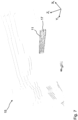
- Figure 5 shows a recorded image 15 of the lidar sensor 2.
- the image 15 contains the reflected laser light 16 with the laser lines 17 that the lidar sensor 2 emitted.
- the image 15 there are areas with high reflectivity 18, i.e. areas with high light intensity. These areas with high reflectivity 18 come about because the laser light 16, i.e. the laser lines 17 emitted by the lidar sensor 2, hit the additional reflection areas 14 of the calibration panel 11.
- areas with low reflectivity 19 are shown. In these areas, the intensity of the reflected laser light 16 is lower than in the areas with high reflectivity 18.
- the laser lines 17 emitted by the lidar sensor 2 hit areas of the calibration panel 11 that absorb a higher light output.
- FIG 6 This is illustrated using another exemplary embodiment.
- the additional reflection areas 14 are drawn on the calibration board 11.
- the known patterns 12 have been omitted in this case for better clarity.
- the reflected laser light 16 is shown in the form of laser lines 17.
- the reflected laser light 16 has a varying intensity profile, depending on which areas of the calibration board the laser light 16 has struck. Areas with high reflectivity 18, i.e. a high intensity value, are shown brighter than areas with low reflectivity 19.
- the processing unit 8 can analyze the image 15 of the lidar sensor 2 to find out in which area the calibration board 11 is located and how the calibration board 11 must be aligned relative to the lidar sensor 2 so that the detected areas with high reflectivity 18 match the known additional reflection areas 14 of the calibration board 11. This is explained in more detail below.
- Figure 7 shows an image 15 of the lidar sensor 2 in which the calibration table 11 is located.
- the measurement data of the lidar sensor 2 are preferably transformed into Cartesian coordinates so that the 3D position in lidar coordinates and its intensity value are known for each measuring point.
- the image 15 of the lidar sensor 2 therefore comprises a large number of measuring points.
- the set of all measuring points can also be referred to as a point cloud.
- the calibration table 11 is now iteratively located in the point cloud.
- the measuring point P max with the highest intensity value is searched for. It is examined whether this point lies within a plane. The detection of such a plane in the point cloud is carried out using known methods, e.g.
- the search area can be restricted by specifying a 3D cuboid in order to avoid errors due to reflections or artifacts.
- the intensity values of the measurement points lying on the flat surface are then binarized. Binarization is carried out using an intensity histogram.
- the binarization threshold is determined so that the percentage of bright points (intensities above the threshold) corresponds to the reflective portion on the calibration panel 11.
- the ratio of reflective to non-reflective points on the calibration panel 11 is known and constant (width of the reflective strips of the additional reflective areas 14 relative to the width of the calibration panel 11).
- Such a binarization of the lidar point cloud on the calibration panel is e.g. in Figure 5 shown.
- the lidar sensor 2 does not scan the space in a plane, but through a flat cone.
- the laser line 17 that the lidar sensor 2 projects onto the calibration board 11 is therefore not a straight line, but a flatly curved hyperbola.
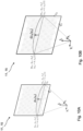
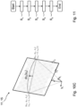
- the Figures 10A, 10B and 10C show the iteration over a curved laser line by moving the start and end points.
- the areas with high reflectivity 18 of the reflected laser light 16 in the form of the laser lines 17 lie exclusively or more than 90%, 95% or more than 98% above the additional reflection areas 14.
- the curvature of the hyperbola is taken into account by taking the deviation from the straight laser line 17, for example, from a lookup table.
- the lookup table can be calculated and saved once for each laser line 17.
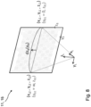
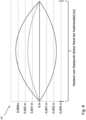
- Figure 9 shows the deviation of the hyperbolas from the straight laser line 17, which is stored in the lookup table.
- the width of the graphic corresponds approximately to the width of the calibration table 11. The figure is shown exaggerated in the Y direction. Even if the deviations between the intersection hyperbola and an approximate intersection line are small, taking the hyperbola intersection into account increases the accuracy of the image.
- the difference dz B (y B ) to the straight laser line 17 is stored in the lookup table for each value y B.
- P Board (y Board , z Board ) (in the board reference system). Since the pose of the calibration board 11 in the camera coordinate system is also known, a transformation T Board ⁇ Camera can also be calculated.
- a transformation T Li-dar ⁇ Camera can be estimated using known methods (least mean square), which converts each measurement point in lidar coordinates into a 3D point. in camera coordinates (ie no longer just the points on the calibration board).
- the 3D transformation can be estimated, for example, as described in opencv pose estimation (see opencv pose estimation (2022)). Using the determined intrinsic camera parameters, the 3D camera points can be transformed into 2D image points.
- Figure 11 shows a flow chart describing a method for position calibration of the camera 1 and the lidar sensor 2 with the calibration board 11.
- a first method step S 1 at least one image 13 of the calibration board 11 is recorded with the camera 1 and a pose of the calibration board 11 relative to the camera 1 is determined based on the known patterns 12 on the calibration board 11.
- laser light 16 in particular in the form of laser lines 17, is radiated from the lidar sensor 2 onto the calibration panel 11.
- a third method step S 3 an image 15 is taken of the calibration panel 11 using the lidar sensor 2, and areas with high reflectivity 18 are determined based on intensity values of the laser light 16 reflected from the calibration panel 11, in particular in the form of the laser lines 17.
- a pose of the calibration panel 11 relative to the lidar sensor 2 is determined based on the known additional reflection areas 14 and the determined areas with high reflectivity 18.
- both images 13, 15 can be converted into a common coordinate system (GKS) based on the determined poses.
- one image 13, 15 can be converted into the coordinate system of the other image 15, 13 based on the determined poses.
- an image 13 from camera 1 can be converted into the lidar coordinate system (LKS) of lidar sensor 2.
- an image 15 from lidar sensor 2 can be converted into the camera coordinate system (KKS) of camera 1.
- conversion values are determined based on the determined poses in order to convert future images 13, 15 into a common coordinate system (GKS) or to convert a future image 13, 15 into the coordinate system of another future image 15, 13.
Landscapes
- Engineering & Computer Science (AREA)
- Physics & Mathematics (AREA)
- Radar, Positioning & Navigation (AREA)
- Remote Sensing (AREA)
- General Physics & Mathematics (AREA)
- Computer Networks & Wireless Communication (AREA)
- Electromagnetism (AREA)
- Mechanical Engineering (AREA)
- Transportation (AREA)
- Automation & Control Theory (AREA)
- Human Computer Interaction (AREA)
- Chemical & Material Sciences (AREA)
- Combustion & Propulsion (AREA)
- Computer Vision & Pattern Recognition (AREA)
- Theoretical Computer Science (AREA)
- Optical Radar Systems And Details Thereof (AREA)
Applications Claiming Priority (1)
| Application Number | Priority Date | Filing Date | Title |
|---|---|---|---|
| DE102022127858.1A DE102022127858A1 (de) | 2022-10-21 | 2022-10-21 | Verfahren zur Positionskalibrierung einer Kamera und eines Lidarsensors mit einer Kalibriertafel sowie ein Positionskalibrierungssystem |
Publications (2)
| Publication Number | Publication Date |
|---|---|
| EP4357809A1 true EP4357809A1 (fr) | 2024-04-24 |
| EP4357809B1 EP4357809B1 (fr) | 2025-09-24 |
Family
ID=88412448
Family Applications (1)
| Application Number | Title | Priority Date | Filing Date |
|---|---|---|---|
| EP23203375.3A Active EP4357809B1 (fr) | 2022-10-21 | 2023-10-13 | Procédé d'étalonnage de position d'une caméra et d'un capteur lidar doté d'un panneau d'étalonnage et système d'étalonnage de position |
Country Status (4)
| Country | Link |
|---|---|
| US (1) | US20240183962A1 (fr) |
| EP (1) | EP4357809B1 (fr) |
| DE (1) | DE102022127858A1 (fr) |
| FI (1) | FI4357809T3 (fr) |
Families Citing this family (2)
| Publication number | Priority date | Publication date | Assignee | Title |
|---|---|---|---|---|
| US20250091592A1 (en) * | 2024-02-14 | 2025-03-20 | Vincent Loccisano | Roadway Sign for Autonomous Vehicle Sensor Calibration |
| CN119756185B (zh) * | 2025-03-04 | 2025-05-30 | 杭州利珀科技股份有限公司 | 基于多线扫相机的玻璃尺寸测量方法、介质及电子设备 |
Citations (3)
| Publication number | Priority date | Publication date | Assignee | Title |
|---|---|---|---|---|
| US20200174107A1 (en) * | 2018-11-30 | 2020-06-04 | Lyft, Inc. | Lidar and camera rotational position calibration using multiple point cloud comparisons |
| US20210316669A1 (en) * | 2020-04-14 | 2021-10-14 | Gm Cruise Holdings Llc | Polyhedral sensor calibration target for calibrating multiple types of sensors |
| CN110766758B (zh) * | 2019-09-12 | 2022-08-09 | 浙江大华技术股份有限公司 | 标定方法、装置、系统及存储装置 |
Family Cites Families (1)
| Publication number | Priority date | Publication date | Assignee | Title |
|---|---|---|---|---|
| US9041762B2 (en) * | 2011-09-26 | 2015-05-26 | Prysm, Inc. | 2-D straight-scan on imaging surface with a raster polygon |
-
2022
- 2022-10-21 DE DE102022127858.1A patent/DE102022127858A1/de active Pending
-
2023
- 2023-10-13 FI FIEP23203375.3T patent/FI4357809T3/fi active
- 2023-10-13 EP EP23203375.3A patent/EP4357809B1/fr active Active
- 2023-10-20 US US18/382,172 patent/US20240183962A1/en active Pending
Patent Citations (3)
| Publication number | Priority date | Publication date | Assignee | Title |
|---|---|---|---|---|
| US20200174107A1 (en) * | 2018-11-30 | 2020-06-04 | Lyft, Inc. | Lidar and camera rotational position calibration using multiple point cloud comparisons |
| CN110766758B (zh) * | 2019-09-12 | 2022-08-09 | 浙江大华技术股份有限公司 | 标定方法、装置、系统及存储装置 |
| US20210316669A1 (en) * | 2020-04-14 | 2021-10-14 | Gm Cruise Holdings Llc | Polyhedral sensor calibration target for calibrating multiple types of sensors |
Non-Patent Citations (2)
| Title |
|---|
| AUS CHAI, Z.SUN, Y.XIONG, Z.: "A novel method for lidar camera calibration by plane fitting.", 2018 IEEE/ASME INTERNATIONAL CONFERENCE ON ADVANCED INTELLIGENT MECHATRONICS, 2018, pages 286 - 291, XP033396459, DOI: 10.1109/AIM.2018.8452339 |
| GARRIDO-JURADO, S., MU-SALINAS, R., MADRID-CUEVAS, F., UND MAR JIM Z, M.: "Automatic generation and detection of highly reliable fiducial markers under occlusion", PATTERN RECOGN, vol. 47, no. 6, June 2014 (2014-06-01), pages 2280 - 2292, XP055601771, DOI: 10.1016/j.patcog.2014.01.005 |
Also Published As
| Publication number | Publication date |
|---|---|
| FI4357809T3 (fi) | 2025-11-28 |
| EP4357809B1 (fr) | 2025-09-24 |
| US20240183962A1 (en) | 2024-06-06 |
| DE102022127858A1 (de) | 2024-05-02 |
Similar Documents
| Publication | Publication Date | Title |
|---|---|---|
| DE112018000827B4 (de) | Inspektionssystem, Steuerungsverfahren und Speichermedium | |
| EP3084347B1 (fr) | Procédé d'exécution et de contrôle d'une étape d'usinage sur une pièce | |
| DE69826753T2 (de) | Optischer Profilsensor | |
| EP4357809B1 (fr) | Procédé d'étalonnage de position d'une caméra et d'un capteur lidar doté d'un panneau d'étalonnage et système d'étalonnage de position | |
| DE102015116047B4 (de) | Prüfvorrichtung und Steuerverfahren für eine Prüfvorrichtung | |
| EP2461181B1 (fr) | Dispositif de détection destiné à l'identification d'objet | |
| DE102016112800B4 (de) | Geführte prüfung einer eingebauten komponente unter verwendung eines mobilen prüfgeräts | |
| EP3182065A1 (fr) | Télémètre portatif et procédé de détection de positions relatives | |
| DE112016001150T5 (de) | Schätzung extrinsischer kameraparameter anhand von bildlinien | |
| DE102017008638A1 (de) | Berührungsfreier sicherheitssensor und arbeitsweise | |
| DE102017212371B4 (de) | Bestimmung einer Marke in einem Datensatz mit mittels zumindest eines Laserscanners erfassten dreidimensionalen Oberflächen-Koordinaten einer Szene | |
| DE102016008689A1 (de) | Sensorkalibriertarget zur Kalibrierung von verschiedenen, auf unterschiedlichen Prinzipien beruhenden Sensoreinrichtungen | |
| DE102009030644B4 (de) | Berührungslose Erfassungseinrichtung | |
| DE102008006449A1 (de) | Verfahren und Vorrichtung zur Überwachung eines Raumvolumens | |
| EP2693218A1 (fr) | Procédé et dispositif pour determiner un arrangement d'articles de laboratoire sur un établi d'un station de travail laboratoire | |
| DE102012023623A1 (de) | Verfahren zum Zusammensetzen von Teilaufnahmen einer Oberfläche eines Objektes zu einer Gesamtaufnahme des Objektes und System zum Erstellen einer Gesamtaufnahme eines Objektes | |
| EP2960883B1 (fr) | Détermination d'au moins une caractéristique d'un véhicule | |
| EP3770804B1 (fr) | Chariot de manutention à détection d'objets | |
| EP4523055B1 (fr) | Procédé de détermination de groupes de points visibles ou non visibles à partir d'un point de vue spécifié | |
| DE102006044615A1 (de) | Verfahren zur Kalibrierung von Bilderfassungseinrichtungen in Fahrzeugen | |
| WO2023247302A1 (fr) | Procédé de détermination d'au moins une fonction de correction pour un système lidar, système lidar, véhicule comprenant au moins un système lidar et système de mesure | |
| DE102012102600B3 (de) | Verfahren zur Verifizierung der Ausrichtung eines Verkehrsüberwachungsgerätes | |
| EP2818824B1 (fr) | Appareil comprenant un capteur optoélectronique 3D et procédé de réconaissance d'objets | |
| WO2023036793A1 (fr) | Procédé de surveillance de chargement | |
| DE102023134244B3 (de) | Verfahren zur Erfassung eines optischen Codes mit einer Kamera |
Legal Events
| Date | Code | Title | Description |
|---|---|---|---|
| PUAI | Public reference made under article 153(3) epc to a published international application that has entered the european phase |
Free format text: ORIGINAL CODE: 0009012 |
|
| STAA | Information on the status of an ep patent application or granted ep patent |
Free format text: STATUS: THE APPLICATION HAS BEEN PUBLISHED |
|
| AK | Designated contracting states |
Kind code of ref document: A1 Designated state(s): AL AT BE BG CH CY CZ DE DK EE ES FI FR GB GR HR HU IE IS IT LI LT LU LV MC ME MK MT NL NO PL PT RO RS SE SI SK SM TR |
|
| STAA | Information on the status of an ep patent application or granted ep patent |
Free format text: STATUS: REQUEST FOR EXAMINATION WAS MADE |
|
| 17P | Request for examination filed |
Effective date: 20240822 |
|
| RBV | Designated contracting states (corrected) |
Designated state(s): AL AT BE BG CH CY CZ DE DK EE ES FI FR GB GR HR HU IE IS IT LI LT LU LV MC ME MK MT NL NO PL PT RO RS SE SI SK SM TR |
|
| STAA | Information on the status of an ep patent application or granted ep patent |
Free format text: STATUS: EXAMINATION IS IN PROGRESS |
|
| 17Q | First examination report despatched |
Effective date: 20241108 |
|
| GRAP | Despatch of communication of intention to grant a patent |
Free format text: ORIGINAL CODE: EPIDOSNIGR1 |
|
| STAA | Information on the status of an ep patent application or granted ep patent |
Free format text: STATUS: GRANT OF PATENT IS INTENDED |
|
| INTG | Intention to grant announced |
Effective date: 20250613 |
|
| GRAS | Grant fee paid |
Free format text: ORIGINAL CODE: EPIDOSNIGR3 |
|
| GRAA | (expected) grant |
Free format text: ORIGINAL CODE: 0009210 |
|
| STAA | Information on the status of an ep patent application or granted ep patent |
Free format text: STATUS: THE PATENT HAS BEEN GRANTED |
|
| AK | Designated contracting states |
Kind code of ref document: B1 Designated state(s): AL AT BE BG CH CY CZ DE DK EE ES FI FR GB GR HR HU IE IS IT LI LT LU LV MC ME MK MT NL NO PL PT RO RS SE SI SK SM TR |
|
| REG | Reference to a national code |
Ref country code: GB Ref legal event code: FG4D Free format text: NOT ENGLISH |
|
| REG | Reference to a national code |
Ref country code: CH Ref legal event code: EP |
|
| REG | Reference to a national code |
Ref country code: DE Ref legal event code: R096 Ref document number: 502023001853 Country of ref document: DE |
|
| REG | Reference to a national code |
Ref country code: IE Ref legal event code: FG4D Free format text: LANGUAGE OF EP DOCUMENT: GERMAN |
|
| REG | Reference to a national code |
Ref country code: FI Ref legal event code: FGE |
|
| PGFP | Annual fee paid to national office [announced via postgrant information from national office to epo] |
Ref country code: DE Payment date: 20251110 Year of fee payment: 3 |
|
| PG25 | Lapsed in a contracting state [announced via postgrant information from national office to epo] |
Ref country code: NO Free format text: LAPSE BECAUSE OF FAILURE TO SUBMIT A TRANSLATION OF THE DESCRIPTION OR TO PAY THE FEE WITHIN THE PRESCRIBED TIME-LIMIT Effective date: 20251224 |
|
| REG | Reference to a national code |
Ref country code: LT Ref legal event code: MG9D |
|
| PGFP | Annual fee paid to national office [announced via postgrant information from national office to epo] |
Ref country code: AT Payment date: 20260113 Year of fee payment: 3 |
|
| PGFP | Annual fee paid to national office [announced via postgrant information from national office to epo] |
Ref country code: FI Payment date: 20251201 Year of fee payment: 3 |
|
| PG25 | Lapsed in a contracting state [announced via postgrant information from national office to epo] |
Ref country code: HR Free format text: LAPSE BECAUSE OF FAILURE TO SUBMIT A TRANSLATION OF THE DESCRIPTION OR TO PAY THE FEE WITHIN THE PRESCRIBED TIME-LIMIT Effective date: 20250924 |
|
| PG25 | Lapsed in a contracting state [announced via postgrant information from national office to epo] |
Ref country code: GR Free format text: LAPSE BECAUSE OF FAILURE TO SUBMIT A TRANSLATION OF THE DESCRIPTION OR TO PAY THE FEE WITHIN THE PRESCRIBED TIME-LIMIT Effective date: 20251225 |
|
| PG25 | Lapsed in a contracting state [announced via postgrant information from national office to epo] |
Ref country code: SE Free format text: LAPSE BECAUSE OF FAILURE TO SUBMIT A TRANSLATION OF THE DESCRIPTION OR TO PAY THE FEE WITHIN THE PRESCRIBED TIME-LIMIT Effective date: 20250924 |
|
| PG25 | Lapsed in a contracting state [announced via postgrant information from national office to epo] |
Ref country code: LV Free format text: LAPSE BECAUSE OF FAILURE TO SUBMIT A TRANSLATION OF THE DESCRIPTION OR TO PAY THE FEE WITHIN THE PRESCRIBED TIME-LIMIT Effective date: 20250924 |
|
| PG25 | Lapsed in a contracting state [announced via postgrant information from national office to epo] |
Ref country code: BG Free format text: LAPSE BECAUSE OF FAILURE TO SUBMIT A TRANSLATION OF THE DESCRIPTION OR TO PAY THE FEE WITHIN THE PRESCRIBED TIME-LIMIT Effective date: 20250924 |
|
| PG25 | Lapsed in a contracting state [announced via postgrant information from national office to epo] |
Ref country code: RS Free format text: LAPSE BECAUSE OF FAILURE TO SUBMIT A TRANSLATION OF THE DESCRIPTION OR TO PAY THE FEE WITHIN THE PRESCRIBED TIME-LIMIT Effective date: 20251224 |
|
| REG | Reference to a national code |
Ref country code: NL Ref legal event code: MP Effective date: 20250924 |
|
| PG25 | Lapsed in a contracting state [announced via postgrant information from national office to epo] |
Ref country code: NL Free format text: LAPSE BECAUSE OF FAILURE TO SUBMIT A TRANSLATION OF THE DESCRIPTION OR TO PAY THE FEE WITHIN THE PRESCRIBED TIME-LIMIT Effective date: 20250924 |
|
| PG25 | Lapsed in a contracting state [announced via postgrant information from national office to epo] |
Ref country code: SM Free format text: LAPSE BECAUSE OF FAILURE TO SUBMIT A TRANSLATION OF THE DESCRIPTION OR TO PAY THE FEE WITHIN THE PRESCRIBED TIME-LIMIT Effective date: 20250924 |
|
| PG25 | Lapsed in a contracting state [announced via postgrant information from national office to epo] |
Ref country code: ES Free format text: LAPSE BECAUSE OF FAILURE TO SUBMIT A TRANSLATION OF THE DESCRIPTION OR TO PAY THE FEE WITHIN THE PRESCRIBED TIME-LIMIT Effective date: 20250924 |
|
| PG25 | Lapsed in a contracting state [announced via postgrant information from national office to epo] |
Ref country code: RO Free format text: LAPSE BECAUSE OF FAILURE TO SUBMIT A TRANSLATION OF THE DESCRIPTION OR TO PAY THE FEE WITHIN THE PRESCRIBED TIME-LIMIT Effective date: 20250924 |
|
| PGFP | Annual fee paid to national office [announced via postgrant information from national office to epo] |
Ref country code: IT Payment date: 20251031 Year of fee payment: 3 |
|
| PG25 | Lapsed in a contracting state [announced via postgrant information from national office to epo] |
Ref country code: IS Free format text: LAPSE BECAUSE OF FAILURE TO SUBMIT A TRANSLATION OF THE DESCRIPTION OR TO PAY THE FEE WITHIN THE PRESCRIBED TIME-LIMIT Effective date: 20260124 |
|
| PG25 | Lapsed in a contracting state [announced via postgrant information from national office to epo] |
Ref country code: PT Free format text: LAPSE BECAUSE OF FAILURE TO SUBMIT A TRANSLATION OF THE DESCRIPTION OR TO PAY THE FEE WITHIN THE PRESCRIBED TIME-LIMIT Effective date: 20260126 Ref country code: CZ Free format text: LAPSE BECAUSE OF FAILURE TO SUBMIT A TRANSLATION OF THE DESCRIPTION OR TO PAY THE FEE WITHIN THE PRESCRIBED TIME-LIMIT Effective date: 20250924 |
|
| PG25 | Lapsed in a contracting state [announced via postgrant information from national office to epo] |
Ref country code: PL Free format text: LAPSE BECAUSE OF FAILURE TO SUBMIT A TRANSLATION OF THE DESCRIPTION OR TO PAY THE FEE WITHIN THE PRESCRIBED TIME-LIMIT Effective date: 20250924 |
|
| PG25 | Lapsed in a contracting state [announced via postgrant information from national office to epo] |
Ref country code: EE Free format text: LAPSE BECAUSE OF FAILURE TO SUBMIT A TRANSLATION OF THE DESCRIPTION OR TO PAY THE FEE WITHIN THE PRESCRIBED TIME-LIMIT Effective date: 20250924 Ref country code: SK Free format text: LAPSE BECAUSE OF FAILURE TO SUBMIT A TRANSLATION OF THE DESCRIPTION OR TO PAY THE FEE WITHIN THE PRESCRIBED TIME-LIMIT Effective date: 20250924 |