EP4357810B1 - Systèmes et procédé de filtrage adaptatif de trame radar - Google Patents
Systèmes et procédé de filtrage adaptatif de trame radar Download PDFInfo
- Publication number
- EP4357810B1 EP4357810B1 EP22202515.7A EP22202515A EP4357810B1 EP 4357810 B1 EP4357810 B1 EP 4357810B1 EP 22202515 A EP22202515 A EP 22202515A EP 4357810 B1 EP4357810 B1 EP 4357810B1
- Authority
- EP
- European Patent Office
- Prior art keywords
- radar
- radar device
- determined
- representation
- frame
- Prior art date
- Legal status (The legal status is an assumption and is not a legal conclusion. Google has not performed a legal analysis and makes no representation as to the accuracy of the status listed.)
- Active
Links
Images


Classifications
-
- G—PHYSICS
- G01—MEASURING; TESTING
- G01S—RADIO DIRECTION-FINDING; RADIO NAVIGATION; DETERMINING DISTANCE OR VELOCITY BY USE OF RADIO WAVES; LOCATING OR PRESENCE-DETECTING BY USE OF THE REFLECTION OR RERADIATION OF RADIO WAVES; ANALOGOUS ARRANGEMENTS USING OTHER WAVES
- G01S7/00—Details of systems according to groups G01S13/00, G01S15/00, G01S17/00
- G01S7/02—Details of systems according to groups G01S13/00, G01S15/00, G01S17/00 of systems according to group G01S13/00
- G01S7/35—Details of non-pulse systems
- G01S7/352—Receivers
- G01S7/354—Extracting wanted echo-signals
-
- G—PHYSICS
- G01—MEASURING; TESTING
- G01S—RADIO DIRECTION-FINDING; RADIO NAVIGATION; DETERMINING DISTANCE OR VELOCITY BY USE OF RADIO WAVES; LOCATING OR PRESENCE-DETECTING BY USE OF THE REFLECTION OR RERADIATION OF RADIO WAVES; ANALOGOUS ARRANGEMENTS USING OTHER WAVES
- G01S13/00—Systems using the reflection or reradiation of radio waves, e.g. radar systems; Analogous systems using reflection or reradiation of waves whose nature or wavelength is irrelevant or unspecified
- G01S13/02—Systems using reflection of radio waves, e.g. primary radar systems; Analogous systems
- G01S13/50—Systems of measurement based on relative movement of target
- G01S13/52—Discriminating between fixed and moving objects or between objects moving at different speeds
- G01S13/522—Discriminating between fixed and moving objects or between objects moving at different speeds using transmissions of interrupted pulse modulated waves
- G01S13/524—Discriminating between fixed and moving objects or between objects moving at different speeds using transmissions of interrupted pulse modulated waves based upon the phase or frequency shift resulting from movement of objects, with reference to the transmitted signals, e.g. coherent MTi
- G01S13/5242—Discriminating between fixed and moving objects or between objects moving at different speeds using transmissions of interrupted pulse modulated waves based upon the phase or frequency shift resulting from movement of objects, with reference to the transmitted signals, e.g. coherent MTi with means for platform motion or scan motion compensation, e.g. airborne MTI
-
- G—PHYSICS
- G01—MEASURING; TESTING
- G01S—RADIO DIRECTION-FINDING; RADIO NAVIGATION; DETERMINING DISTANCE OR VELOCITY BY USE OF RADIO WAVES; LOCATING OR PRESENCE-DETECTING BY USE OF THE REFLECTION OR RERADIATION OF RADIO WAVES; ANALOGOUS ARRANGEMENTS USING OTHER WAVES
- G01S13/00—Systems using the reflection or reradiation of radio waves, e.g. radar systems; Analogous systems using reflection or reradiation of waves whose nature or wavelength is irrelevant or unspecified
- G01S13/02—Systems using reflection of radio waves, e.g. primary radar systems; Analogous systems
- G01S13/50—Systems of measurement based on relative movement of target
- G01S13/52—Discriminating between fixed and moving objects or between objects moving at different speeds
- G01S13/538—Discriminating between fixed and moving objects or between objects moving at different speeds eliminating objects that have not moved between successive antenna scans, e.g. area MTi
-
- G—PHYSICS
- G01—MEASURING; TESTING
- G01S—RADIO DIRECTION-FINDING; RADIO NAVIGATION; DETERMINING DISTANCE OR VELOCITY BY USE OF RADIO WAVES; LOCATING OR PRESENCE-DETECTING BY USE OF THE REFLECTION OR RERADIATION OF RADIO WAVES; ANALOGOUS ARRANGEMENTS USING OTHER WAVES
- G01S13/00—Systems using the reflection or reradiation of radio waves, e.g. radar systems; Analogous systems using reflection or reradiation of waves whose nature or wavelength is irrelevant or unspecified
- G01S13/02—Systems using reflection of radio waves, e.g. primary radar systems; Analogous systems
- G01S13/06—Systems determining position data of a target
- G01S13/08—Systems for measuring distance only
- G01S13/32—Systems for measuring distance only using transmission of continuous waves, whether amplitude-, frequency-, or phase-modulated, or unmodulated
- G01S13/34—Systems for measuring distance only using transmission of continuous waves, whether amplitude-, frequency-, or phase-modulated, or unmodulated using transmission of continuous, frequency-modulated waves while heterodyning the received signal, or a signal derived therefrom, with a locally-generated signal related to the contemporaneously transmitted signal
-
- G—PHYSICS
- G01—MEASURING; TESTING
- G01S—RADIO DIRECTION-FINDING; RADIO NAVIGATION; DETERMINING DISTANCE OR VELOCITY BY USE OF RADIO WAVES; LOCATING OR PRESENCE-DETECTING BY USE OF THE REFLECTION OR RERADIATION OF RADIO WAVES; ANALOGOUS ARRANGEMENTS USING OTHER WAVES
- G01S13/00—Systems using the reflection or reradiation of radio waves, e.g. radar systems; Analogous systems using reflection or reradiation of waves whose nature or wavelength is irrelevant or unspecified
- G01S13/02—Systems using reflection of radio waves, e.g. primary radar systems; Analogous systems
- G01S13/50—Systems of measurement based on relative movement of target
- G01S13/505—Systems of measurement based on relative movement of target using Doppler effect for determining closest range to a target or corresponding time, e.g. miss-distance indicator
-
- G—PHYSICS
- G01—MEASURING; TESTING
- G01S—RADIO DIRECTION-FINDING; RADIO NAVIGATION; DETERMINING DISTANCE OR VELOCITY BY USE OF RADIO WAVES; LOCATING OR PRESENCE-DETECTING BY USE OF THE REFLECTION OR RERADIATION OF RADIO WAVES; ANALOGOUS ARRANGEMENTS USING OTHER WAVES
- G01S13/00—Systems using the reflection or reradiation of radio waves, e.g. radar systems; Analogous systems using reflection or reradiation of waves whose nature or wavelength is irrelevant or unspecified
- G01S13/02—Systems using reflection of radio waves, e.g. primary radar systems; Analogous systems
- G01S13/50—Systems of measurement based on relative movement of target
- G01S13/52—Discriminating between fixed and moving objects or between objects moving at different speeds
- G01S13/536—Discriminating between fixed and moving objects or between objects moving at different speeds using transmission of continuous unmodulated waves, amplitude-, frequency-, or phase-modulated waves
-
- G—PHYSICS
- G01—MEASURING; TESTING
- G01S—RADIO DIRECTION-FINDING; RADIO NAVIGATION; DETERMINING DISTANCE OR VELOCITY BY USE OF RADIO WAVES; LOCATING OR PRESENCE-DETECTING BY USE OF THE REFLECTION OR RERADIATION OF RADIO WAVES; ANALOGOUS ARRANGEMENTS USING OTHER WAVES
- G01S13/00—Systems using the reflection or reradiation of radio waves, e.g. radar systems; Analogous systems using reflection or reradiation of waves whose nature or wavelength is irrelevant or unspecified
- G01S13/02—Systems using reflection of radio waves, e.g. primary radar systems; Analogous systems
- G01S13/50—Systems of measurement based on relative movement of target
- G01S13/58—Velocity or trajectory determination systems; Sense-of-movement determination systems
- G01S13/583—Velocity or trajectory determination systems; Sense-of-movement determination systems using transmission of continuous unmodulated waves, amplitude-, frequency-, or phase-modulated waves and based upon the Doppler effect resulting from movement of targets
-
- G—PHYSICS
- G01—MEASURING; TESTING
- G01S—RADIO DIRECTION-FINDING; RADIO NAVIGATION; DETERMINING DISTANCE OR VELOCITY BY USE OF RADIO WAVES; LOCATING OR PRESENCE-DETECTING BY USE OF THE REFLECTION OR RERADIATION OF RADIO WAVES; ANALOGOUS ARRANGEMENTS USING OTHER WAVES
- G01S7/00—Details of systems according to groups G01S13/00, G01S15/00, G01S17/00
- G01S7/02—Details of systems according to groups G01S13/00, G01S15/00, G01S17/00 of systems according to group G01S13/00
- G01S7/35—Details of non-pulse systems
- G01S7/352—Receivers
-
- G—PHYSICS
- G01—MEASURING; TESTING
- G01S—RADIO DIRECTION-FINDING; RADIO NAVIGATION; DETERMINING DISTANCE OR VELOCITY BY USE OF RADIO WAVES; LOCATING OR PRESENCE-DETECTING BY USE OF THE REFLECTION OR RERADIATION OF RADIO WAVES; ANALOGOUS ARRANGEMENTS USING OTHER WAVES
- G01S7/00—Details of systems according to groups G01S13/00, G01S15/00, G01S17/00
- G01S7/02—Details of systems according to groups G01S13/00, G01S15/00, G01S17/00 of systems according to group G01S13/00
- G01S7/41—Details of systems according to groups G01S13/00, G01S15/00, G01S17/00 of systems according to group G01S13/00 using analysis of echo signal for target characterisation; Target signature; Target cross-section
- G01S7/415—Identification of targets based on measurements of movement associated with the target
Definitions
- the present invention relates to processing of radar frames, and specifically to filtering out a representation of an object from a radar frame captured by a radar device.
- each radar frame can be performed by which radar data relating to static objects, such as the ground, buildings, parked cars etc, may be removed from each radar frame.
- static objects such as the ground, buildings, parked cars etc
- processing may be performed in applications when moving objects in the scene are of more interest than static objects.
- the processing is fairly straightforward when the radar device is firmly mounted on a stationary rigid support, such as a wall.
- the radar device is mounted on a stationary non-rigid support, e.g. a non-rigid pole that can vibrate or sway back and forth, the radar device may thus move thereby causing a relative movement between the static objects and the moving radar device.
- radar data in relation to static objects may not be removed from the radar frames since the static objects do no longer appear as static due to the movement of the radar device.
- US 2006/028369 A1 describes a radar unit including a data acquisition device that collects data from the reflected microwave signals from the target area and analyses the data. Unwanted motion interference generated by movement of a radar detection system is suppressed, whereby moving or breathing of a living body can be differentiated from a stationary target.
- US 6 970 128 B1 relates to a see-through-the-wall (STTW) imaging system using a plurality of geographically separated positioning transmitters and comprising an imaging unit which performs synthetic aperture imaging and compensates for the complex motion of user.
- STTW see-through-the-wall
- US 2007/132634 A1 discloses a phased array radar system, which estimates a radar platform angular motion of the phased array radar system (100), wherein angular motion includes roll, pitch and yaw motion.
- angular motion includes roll, pitch and yaw motion.
- Each array subsection response of a set of array subsection responses for the radar platform angular motion is compensated by applying continuous time varying phase adjustments to each individual array subsection response. Time varying phase adjustments are determined in response to the radar platform angular motion.
- a method for adaptively filtering out a representation of an object from a radar frame captured by a radar device is provided.
- a maximum signal strength at zero velocity is obtained in a range bin comprising a detection corresponding to the object in range Doppler representations of a set of radar frames captured by the radar device during a time period preceding the radar frame, which time period comprises at least one period of an oscillatory movement of the radar device in relation to stationary objects in a scene monitored by the radar device.
- a motion vector is obtained representing a determined magnitude and direction of motion of the radar device due to the oscillatory movement of the radar device.
- the radar frame captured by the radar device having the determined magnitude and direction of motion is received and a range Doppler representation of the radar frame is produced.
- a direction vector representing a direction from the radar device to the object is determined, and a radial relative velocity between the object and the radar device is determined based on the obtained motion vector and the determined direction vector.
- an interval is set around the determined radial relative velocity based on the determined radial relative velocity and the determined maximum signal strength. On condition that the detection is located within the set interval, a representation of the object from the radar frame is filtered out, and on condition that the detection is located outside the set interval, the detection corresponding to the object is not filtered out from the radar frame.
- the radial relative velocity between the object and the radar device at the time when the radar frame is captured can be determined.
- the radial relative velocity is then used together with the maximum signal strength to determine an interval around the radial relative velocity in the range bin in the range Doppler representation of the radar frame, which range bin comprises the detection corresponding to the object.
- the interval is then used to determine whether a representation of the object is filtered out from the radar frame.
- the filtering is more adaptive to the current radial relative velocity. If a general increase of the interval were to be used, there would be a higher risk that a slowly moving object would be filtered out from the radar frame.
- the act of obtaining a maximum signal strength at zero velocity comprises receiving the set of radar frames captured by the radar device during a time period preceding the radar frame, which time period comprises at least one period of the oscillatory movement of the radar device in relation to stationary objects in a scene monitored by the radar device.
- Range Doppler representations are produced of the set of radar frames and a detection corresponding to the object is identified in each of the range Doppler representations of the set of radar frames.
- a signal strength at zero velocity is determined of the detection corresponding to the object in each range Doppler representation, and the maximum signal strength is determined as a maximum of the determined signal strengths.
- a method for adaptively filtering out a representation of an object from a first radar frame of a plurality of radar frames captured by a radar device For each radar frame of the plurality of radar frames a maximum signal strength at zero velocity in a range bin comprising the detection corresponding to the object is obtained in range Doppler representations of a set of radar frames captured by the radar device during a time period preceding the first radar frame, which time period comprises at least one period of an oscillatory movement of the radar device in relation to stationary objects in a scene monitored by the radar device. Furthermore, a motion vector is obtained representing a determined magnitude and direction of motion of the radar device due to the oscillatory movement of the radar device.
- the radar frame captured by the radar device having the determined magnitude and direction of motion is received and a range Doppler representation is produced of the radar frame.
- a direction vector representing a direction from the radar device to the detected object is determined, and a radial relative velocity between the object and the radar device is determined based on the determined motion vector and the determined direction vector.
- an interval around the determined radial relative velocity is set based on the determined radial relative velocity and the determined maximum signal strength.
- a common interval is then calculated as an average of the set intervals for the plurality of radar frames.
- the detection corresponding to the object On condition that the detection corresponding to the object is located within the calculated common interval in the range bin of the range Doppler representation of the first radar frame, the detection corresponding to the object is filtered out from the first radar frame. On condition that the detection corresponding to the object is located outside the calculated common interval in the range bin of the range Doppler representation of the first radar frame, the detection corresponding to the object is not filtered out from the first radar frame.
- static objects that due to the oscillatory movement of the radar device appear to have a velocity different from zero velocity in the range Doppler representation of the radar frame can be identified as static objects and/or representations of such objects can be filtered out from the radar frame.
- the oscillatory movement of the radar device is due to an oscillatory movement of a support structure on which the radar device is mounted.
- a non-transitory computer-readable storage medium having stored thereon instructions for implementing the method according to the first aspect, or the method according to the second aspect, when executed by a device having processing capabilities.
- a device for adaptively filtering out a representation of an object from a radar frame captured by a radar device comprises circuitry configured to execute a first obtaining function, a second obtaining function, a receiving function, a producing function, a first determining function, a second determining function, a setting function, and a filtering function.
- the first obtaining function is configured to obtain a maximum signal strength at zero velocity in a range bin comprising the detection corresponding to the object in range Doppler representations of a set of radar frames captured by the radar device during a time period preceding the radar frame, which time period comprises at least one period of an oscillatory movement of the radar device in relation to stationary objects in a scene monitored by the radar device.
- the second obtaining function is configured to obtain a motion vector representing a determined magnitude and direction of motion of the radar device due to the oscillatory movement of the radar device.
- the receiving function is configured to receive the radar frame captured by the radar device having the determined magnitude and direction of motion.
- the producing function is configured to produce a range Doppler representation of the radar frame.
- the first determining function is configured to determine a direction vector representing a direction from the radar device to the object.
- the second determining function is configured to determine a radial relative velocity between the object and the radar device based on the determined motion vector and the determined direction vector.
- the setting function is configured to, for the range bin in the range Doppler representation comprising the detection corresponding to the object, set an interval around the determined radial relative velocity based on the determined radial relative velocity and the determined maximum signal strength.
- the filtering function is configured to filter out a representation of the object from the first radar frame on condition that the detection corresponding to the object is located within the set interval, and to refrain from filtering out the representation of the object from the first radar frame on condition that the detection corresponding to the object is located outside the set interval.
- a device for adaptively filtering out a representation of an object from a first radar frame of a plurality of radar frames captured by a radar device comprises circuitry configured to execute, for each radar frame of the plurality of radar frames, a first obtaining function, a second obtaining function, a receiving function, a producing function, a first determining function, a second determining function, and a setting function.
- the first obtaining function is configured to obtain a maximum signal strength at zero velocity in a range bin comprising the detection corresponding to the object in range Doppler representations of a set of radar frames captured by the radar device during a time period preceding the radar frame, which time period comprises at least one period of an oscillatory movement of the radar device in relation to stationary objects in a scene monitored by the radar device.
- the second obtaining function is configured to obtain a motion vector representing a determined magnitude and direction of motion of the radar device due to the oscillatory movement of the radar device.
- the receiving function is configured to receive the radar frame captured by the radar device having the determined magnitude and direction of motion.
- the producing function is configured to produce a range Doppler representation of the radar frame.
- the first determining function is configured to determine a direction vector representing a direction from the radar device to the object.
- the second determining function is configured to determine a radial relative velocity between the object and the radar device based on the determined motion vector and the determined direction vector.
- the setting function is configured to, for the range bin in the range Doppler representation comprising the detection corresponding to the object, set an interval around the determined radial relative velocity based on the determined radial relative velocity and the determined maximum signal strength.
- the circuitry is further configured to execute a calculating function and a filtering function.
- the calculating function is configured to calculate a common interval as an average of the set intervals for the plurality of radar frames.
- the filtering function is configured to filter out a representation of the object from the first radar frame on condition that the detection corresponding to the object is located within the common interval in the range bin of the range Doppler representation of the first radar frame, and to refrain from filtering out the representation of the object from the first radar frame on condition that the detection corresponding to the object is located outside the common interval in the range bin of the range Doppler representation of the first radar frame.
- the oscillatory movement of the radar device is due to an oscillatory movement of a support structure on which the radar device is mounted.
- the invention is applicable in scenarios where a radar device is stationary but not rigidly mounted such there may be a relative oscillation movement between static objects in a scene the radar device is monitoring and the radar device itself due to an oscillatory movement of the radar device in relation to stationary objects in a scene monitored by the radar device.
- This may for example occur when the radar device is mounted on a stationary non-rigid support, e.g. a non-rigid pole, that may oscillate back and forth.
- Such oscillation may for example occur due to wind or other physical impact to the non-rigid support.
- the radar device is of a type that enables determining of a velocity of an object detected by the radar device.
- the radar device may be a frequency modulated continuous wave (FMCW) radar device that uses short beat signals (chirps) for which the frequency varies over time, typically the frequency is ramped up or ramped down.
- FMCW frequency modulated continuous wave
- PMCW phase modulated continuous wave
- the radar device is further of a type that enables determining a direction vector from the radar device to an object detected by the radar device.
- the radar device may be a multiple-input multiple output (MIMO) radar device.
- MIMO multiple-input multiple output
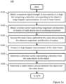
- Embodiments of a method 100 for adaptively filtering out a representation of an object from a radar frame captured by a radar device will now be described in relation to the flow charts in Figure 1a and Figure 1b .
- the method 100 relates to adaptive filtering in relation to one object.
- the principles of the method can be used for adaptive filtering in relation to all objects of a radar frame either in sequence or in parallel.
- the method 100 comprises obtaining S110 a maximum signal strength at zero velocity in a range bin comprising a detection corresponding to the object in range Doppler representations of a set of radar frames captured by the radar device.
- Signal strength here relates to the signal strength of the reflected signal received at the radar device.
- the set of radar frames are captured during a time period preceding the radar frame, i.e. preceding the time the radar frame is captured. Furthermore, the time period is made sufficiently long to comprise at least one period of the oscillatory movement of the radar device. This is to ensure that the maximum signal strength of the detection corresponding to the object will be at, or at least close to, zero velocity in the range Doppler representation of at least one radar frame of the set of radar frames. For example, if the period of the oscillatory movement is 2 seconds and there are 10 radar frames per second, the set of radar frames should comprise at least 20 radar frames.
- a range Doppler representation may be produced by logically arranging analog-to-digital converted data corresponding to downconverted chirps as columns of a matrix.
- An FFT in each column resolves objects in range from the radar device such that each row is a range bin including detections of objects within a range interval from the radar device.
- An FFT along a row resolves each row (range bin) in velocity in relation to the radar device such that each column includes detections of objects within a velocity interval in relation to the radar device.
- the range Doppler representation includes detections, which detections' position in relation to a vertical y-axis correspond to objects in the scene at different ranges from the radar device. The detections' positions in relation to a horizontal x-axis corresponds to the radial velocity between the radar device and the object.
- the method 100 is described in relation to one object.
- the filtering can be performed in relation to all objects in the radar frame.
- the maximum signal strength at zero velocity in each range bin over the set of radar frames may then be obtained.
- the remaining steps S120-S194 of the method 100 is then performed for each range bin in the radar frame based on the respective maximum signal strength.
- it may be limited to range bins that include objects that are likely to be static. This can be achieved by identifying all range bins having a maximum signal strength at zero velocity that is over a threshold indicating a detection corresponding to an object.
- the remaining steps of the method 100 is then performed only for the identified range bins in the radar frame.
- the act of obtaining S110 a maximum signal strength at zero velocity may comprise receiving the set of radar frames captured by the radar device during the time period preceding the radar frame. Range Doppler representations are then produced of the set of radar frames. A signal strength at zero velocity is then determined in the range bin comprising the detection corresponding to the object in each range Doppler representation, and the maximum signal strength is determined as a maximum of the determined signal strengths.
- the method further comprises obtaining S120 a motion vector representing a determined magnitude and direction of motion of the radar device in relation to stationary objects in a scene monitored by the radar device.
- the relative movement between the radar device and stationary objects in the scene is due to the oscillatory movement of the radar device. Furthermore, as the movement of the radar device is oscillatory, the magnitude and direction of motion of the radar device will vary over time. To this end, the magnitude and direction of motion is determined at the time when the radar frame is captured by the radar device.
- the motion vector can be obtained by means of receiving measurements by an accelerometer arranged in the radar device, which measurements were made at the time of capturing the radar frame. In alternative the motion vector can be obtained by determining the relative velocity in relation to a set of objects in the scene which have been identified as being static in the scene and which have known locations in relation to the radar device.
- the method 100 further comprises receiving S130 the radar frame captured by the radar device and producing S 140 a range Doppler representation of the radar frame.
- the radar device had the determined magnitude and direction of movement at the time when the radar frame was captured.
- the range Doppler representation includes detections, which detections' position in relation to a vertical y-axis correspond to objects in the scene at different ranges from the radar device. The detections' positions in relation to a horizontal x-axis corresponds to the radial velocity between the radar device and the object. Due to the oscillatory movement, the radar device has a determined magnitude and direction of motion in relation to stationary objects when the radar frame is captured. Hence, detections corresponding to static objects in the scene will not be located at a location in the range Doppler representation corresponding to zero velocity.
- the method 100 further comprises determining S150 a direction vector representing a direction from the radar device to the object, and determining S160 a radial relative velocity between the object and the radar device based on the obtained motion vector and the determined direction vector.
- the radar device may be a MIMO radar device.
- the radar device may further be a FMCW radar device or a PMCW radar device.
- an interval is set S170 around the determined radial relative velocity.
- the interval is set in relation to the radar frame and is based on the determined radial relative velocity which is specific to the radar frame and the determined maximum signal strength.
- the interval is used to determine whether a representation of the object should be filtered out from the radar frame. Specifically, on condition C190 that the detection is located within the set interval, a representation of the object is filtered out S192 from the radar frame, and on condition C190 that the detection is located outside the set interval, the representation of the object is not filtered out S194 from the radar frame.
- a detection being located within the set interval is meant that any energy outside the interval will be below a threshold for what is considered to be a detection.
- the detection being located outside the set interval is meant that energy outside the interval is above the threshold for what is considered to be a detection.
- the interval being set around the determined radial relative velocity is meant that the interval starts below the determined radial relative velocity and ends above the determined radial relative velocity.
- the interval may be symmetrical around the determined radial relative velocity, i.e. such that the determined radial relative velocity is in the middle of the interval.
- the set interval around the determined radial relative velocity is used instead of a fixed guard interval around zero velocity set for all radar frames in prior art.
- the interval is set based in part on the determined radial relative velocity which is determined based on the determined magnitude and direction of movement of the radar device at the time the radar frame was captured.
- the set interval for the radar frame is adapted to the determined magnitude and direction of movement of the radar device at the time the radar frame was captured.
- the filtering will be adapted such that the representation of the object will be filtered out from the radar frame even if the detection in the range bin would not have been considered to correspond to a static object if the prior art methods using a fixed guard interval would have been used.
- the larger the radial relative velocity is the larger the interval may be set.
- Figure 2a and Figure 2b show flow charts in relation to embodiments of a method for adaptively filtering out a representation of an object from a first radar frame of a plurality of radar frames captured by a radar device.
- the acts of obtaining S210 a maximum signal strength, obtaining S220 a motion vector, receiving S230 the radar frame, producing S240 a range doppler representation, determining S250 a direction vector, determining S260 a radial relative velocity, and setting S270 an interval are performed for each radar frame i of a plurality of radar frames consisting of n radar frames.
- S210-S270 reference is made to the details and options for the corresponding acts S110-S170 of the method 100 described in relation to Figure 1a and Figure 1b .
- One interval for the range bin is thus set in relation to each radar frame.
- a common interval for the range bin is then calculated S280 as an average of the set intervals for the plurality of radar frames.
- the common interval is then used to determine whether a representation of the object should be filtered out from the first radar frame.
- the common interval is located around the radial relative velocity as determined at the time when the first radar frame was captured by the radar device. Specifically, on condition C290 that the detection is located within the common interval, a representation of the object is filtered out S292 from the radar frame, and on condition C290 that the detection is located outside the common interval, the representation of the object is not filtered out S194 from the radar frame.
- Figure 3 shows a block diagram in relation to embodiments of a device 300 for adaptively filtering out a representation of an object from a radar frame captured by a radar device.
- the device 300 comprises a circuitry 310.
- the circuitry 310 is configured to carry out functions of the device 300.
- the circuitry 310 may include a processor 312, such as for example a central processing unit (CPU), graphical processing unit (GPU), tensor processing unit (TPU), microcontroller, or microprocessor.
- the processor 312 is configured to execute program code.
- the program code may for example be configured to carry out the functions of the device 300.
- the device 300 may further comprise a memory 320.
- the memory 320 may be one or more of a buffer, a flash memory, a hard drive, a removable media, a volatile memory, a non-volatile memory, a random access memory (RAM), or another suitable device.
- the memory 320 may include a non-volatile memory for long term data storage and a volatile memory that functions as device memory for the circuitry 310.
- the memory 320 may exchange data with the circuitry 310 over a data bus. Accompanying control lines and an address bus between the memory 320 and the circuitry 310 also may be present.
- Functions of the device 300 may be embodied in the form of executable logic routines (e.g., lines of code, software programs, etc.) that are stored on a non-transitory computer readable medium (e.g., the memory 320) of the device 300 and are executed by the circuitry 310 (e.g., using the processor 312).
- the functions of the device 300 may be a stand-alone software application or form a part of a software application that carries out additional tasks related to the device 300.
- the described functions may be considered a method that a processing unit, e.g. the processor 312 of the circuitry 310 is configured to carry out.
- the described functions may be implemented in software, such functionality may as well be carried out via dedicated hardware or firmware, or some combination of hardware, firmware and/or software.
- the circuitry 310 is configured to execute a first obtaining function 331, a second obtaining function 332, a receiving function 333, a producing function 334, a first determining function 335, a second determining function 336, a setting function 337 and a filtering function 339.
- the first obtaining function 331 is configured to obtain a maximum signal strength at zero velocity in a range bin comprising the detection corresponding to the object in range Doppler representations of a set of radar frames captured by the radar device during a time period preceding the radar frame, which time period comprises at least one period of an oscillatory movement of the radar device in relation to stationary objects in a scene monitored by the radar device.
- the second obtaining function 332 is configured to obtain a motion vector representing a determined magnitude and direction of motion of the radar device due to the oscillatory movement of the radar device.
- the receiving function 333 is configured to receive the radar frame captured by the radar device having the determined magnitude and direction of motion.
- the producing function 334 is configured to produce a range Doppler representation of the radar frame.
- the first determining function 335 is configured to determine a direction vector representing a direction from the radar device to the object.
- the second determining function 336 is configured to determine a radial relative velocity between the object and the radar device based on the determined motion vector and the determined direction vector.
- the setting function 337 is configured to, for the range bin in the range Doppler representation comprising the detection corresponding to the object, set an interval around the determined radial relative velocity based on the determined radial relative velocity and the determined maximum signal strength.
- the filtering function 339 is configured to filter out a representation of the object from the first radar frame on condition that the detection corresponding to the object is located within the set interval, and to refrain from filtering out the representation of the object from the first radar frame on condition that the detection corresponding to the object is located outside the set interval.
- Figure 4 shows a block diagram in relation to embodiments of a device 400 for adaptively filtering out a representation of an object from a first radar frame of a plurality of radar frames captured by a radar device.
- the device 400 comprises a circuitry 410.
- the circuitry 410 is configured to carry out functions of the device 400.
- the circuitry 410 may include a processor 412, such as for example a central processing unit (CPU), graphical processing unit (GPU), tensor processing unit (TPU), microcontroller, or microprocessor.
- the processor 112 is configured to execute program code.
- the program code may for example be configured to carry out the functions of the device 400.
- the device 400 may further comprise a memory 420.
- the memory 420 may be one or more of a buffer, a flash memory, a hard drive, a removable media, a volatile memory, a non-volatile memory, a random access memory (RAM), or another suitable device.
- the memory 420 may include a non-volatile memory for long term data storage and a volatile memory that functions as device memory for the circuitry 410.
- the memory 420 may exchange data with the circuitry 410 over a data bus. Accompanying control lines and an address bus between the memory 420 and the circuitry 410 also may be present.
- Functions of the device 400 may be embodied in the form of executable logic routines (e.g., lines of code, software programs, etc.) that are stored on a non-transitory computer readable medium (e.g., the memory 420) of the device 400 and are executed by the circuitry 410 (e.g., using the processor 412).
- the functions of the device 400 may be a stand-alone software application or form a part of a software application that carries out additional tasks related to the device 400.
- the described functions may be considered a method that a processing unit, e.g. the processor 412 of the circuitry 410 is configured to carry out.
- the described functions may be implemented in software, such functionality may as well be carried out via dedicated hardware or firmware, or some combination of hardware, firmware and/or software.
- the circuitry 410 is configured to execute, for each radar frame of the plurality of radar frames, a first obtaining function 431, a second obtaining function 432, a receiving function 433, a producing function 434, a first determining function 435, a second determining function 436.
- the circuitry 410 is further configured to execute a calculating function 438 and a filtering function 439.
- the first obtaining function 431 is configured to obtain a maximum signal strength at zero velocity in a range bin comprising the detection corresponding to the object in range Doppler representations of a set of radar frames captured by the radar device during a time period preceding the radar frame, which time period comprises at least one period of an oscillatory movement of the radar device in relation to stationary objects in a scene monitored by the radar device.
- the second obtaining function 432 is configured to obtain a motion vector representing a determined magnitude and direction of motion of the radar device due to the oscillatory movement of the radar device.
- the receiving function 433 is configured to receive the radar frame captured by the radar device having the determined magnitude and direction of motion.
- the producing function 434 is configured to produce a range Doppler representation of the radar frame.
- the first determining function 435 is configured to determine a direction vector representing a direction from the radar device to the object.
- the second determining function 436 is configured to determine a radial relative velocity between the object and the radar device based on the determined motion vector and the determined direction vector.
- the setting function 437 is configured to, for the range bin in the range Doppler representation comprising the detection corresponding to the object, set an interval around the determined radial relative velocity based on the determined radial relative velocity and the determined maximum signal strength.
- the circuitry is further configured to execute a calculating function 438 and a filtering function 439.
- the calculating function 438 is configured to calculate a common interval as an average of the set intervals for the plurality of radar frames.
- the filtering function 439 is configured to filter out a representation of the object from the first radar frame on condition that the detection corresponding to the object is located within the common interval in the range bin of the range Doppler representation of the first radar frame, and to refrain from filtering out the representation of the object from the first radar frame on condition that the detection corresponding to the object is located outside the common interval in the range bin of the range Doppler representation of the first radar frame.
Landscapes
- Engineering & Computer Science (AREA)
- Radar, Positioning & Navigation (AREA)
- Remote Sensing (AREA)
- Computer Networks & Wireless Communication (AREA)
- Physics & Mathematics (AREA)
- General Physics & Mathematics (AREA)
- Radar Systems Or Details Thereof (AREA)
Claims (9)
- Procédé pour éliminer, par filtrage adaptatif d'une image radar capturée par un dispositif radar, une représentation d'un objet, ce procédé comprenant :l'obtention d'une intensité de signal maximum à une vitesse nulle dans une cellule de distance comprenant une détection correspondant à l'objet dans des représentations de portée Doppler d'un ensemble d'images radar capturées par le dispositif radar pendant une période de temps précédant l'image radar, laquelle période de temps comprend au moins une période d'un mouvement d'oscillation du dispositif radar par rapport à des objets immobiles dans une scène surveillée par le dispositif radar ;l'obtention d'un vecteur de mouvement représentant une grandeur et une direction déterminées du mouvement du dispositif radar dû au mouvement d'oscillation du dispositif radar ;la réception de l'image radar capturée par le dispositif radar ayant la grandeur et la direction de mouvement obtenues ;la production d'une représentation de portée Doppler de l'image radar ;
la détermination d'un vecteur de direction représentant une direction du dispositif radar à l'objet ;la détermination d'une vitesse radiale relative entre l'objet et le dispositif radar en se basant sur le vecteur de mouvement obtenu et sur le vecteur de direction déterminé ;pour la cellule de distance dans la représentation de portée Doppler comprenant la détection correspondant à l'objet, la définition d'un intervalle autour de la vitesse radiale relative déterminée de l'objet en se basant sur la vitesse radiale relative déterminée et sur l'intensité de signal maximum déterminée ;à condition que la détection correspondant à l'objet soit située dans l'intervalle défini, l'élimination par filtrage de l'image radar d'une représentation de l'objet ; età condition que la détection correspondant à l'objet soit située en dehors de l'intervalle défini, l'abstention de l'élimination par filtrage de l'image radar de la représentation de l'objet. - Procédé selon la revendication 1, dans lequel l'acte d'obtention d'une intensité de signal maximum à une vitesse nulle comprend :la réception d'un ensemble d'images radar capturées par le dispositif radar pendant une période de temps précédant l'image radar, laquelle période de temps comprend au moins une période du mouvement d'oscillation du dispositif radar par rapport à des objets immobiles dans une scène surveillée par le dispositif radar ;la production de représentations de portée Doppler de l'ensemble d'images radar ;
la détermination d'une intensité de signal à une vitesse nulle dans la cellule de distance comprenant la détection correspondant à l'objet dans chaque représentation de portée Doppler ; etla détermination de l'intensité de signal maximum comme un maximum des intensités de signaux déterminées. - Procédé pour éliminer, par filtrage adaptatif d'une première image radar parmi une pluralité d'images radar capturées par un dispositif radar, une représentation d'un objet, ce procédé comprenant :
pour chaque image radar parmi la pluralité d'images radar :l'obtention d'une intensité de signal maximum à une vitesse nulle dans une cellule de distance comprenant une détection correspondant à l'objet dans des représentations de portée Doppler d'un ensemble d'images radar capturées par le dispositif radar pendant une période de temps précédant l'image radar, laquelle période timeDurationForQCL comprend au moins une période d'un mouvement d'oscillation du dispositif radar par rapport à des objets immobiles dans une scène surveillée par le dispositif radar ;l'obtention d'un vecteur de mouvement représentant une grandeur et une direction déterminées du mouvement du dispositif radar dû au mouvement d'oscillation du dispositif radar ;la réception de l'image radar capturée par le dispositif radar ayant la grandeur et la direction de mouvement déterminées ;la production d'une représentation de portée Doppler de l'image radar ;la détermination d'un vecteur de direction représentant une direction du dispositif radar à l'objet détecté ;la détermination d'une vitesse radiale relative entre l'objet et le dispositif radar en se basant sur le vecteur de mouvement déterminé et sur le vecteur de direction déterminé ; etpour la cellule de distance dans la représentation de portée Doppler comprenant la détection correspondant à l'objet, la définition d'un intervalle autour de la vitesse radiale relative déterminée de l'objet en se basant sur la vitesse radiale relative déterminée et sur l'intensité de signal maximum déterminée ;le calcul d'un intervalle commun comme une moyenne des intervalles définis pour la pluralité d'images radar ;à condition que la détection correspondant à l'objet soit située dans l'intervalle commun calculé dans la cellule de distance de la représentation de portée Doppler de la première image radar, l'élimination, par filtrage de la première image radar, d'une représentation de l'objet ; età condition que la détection correspondant à l'objet soit située en dehors de l'intervalle commun calculé dans la cellule de distance de la représentation de portée Doppler de la première image radar, l'abstention de l'élimination, par filtrage de la première image radar, de la représentation de l'objet. - Procédé selon l'une quelconque des revendications précédentes, dans lequel le mouvement d'oscillation du dispositif radar est dû à un mouvement d'oscillation d'une structure de support sur laquelle le dispositif radar est monté.
- Support de stockage non transitoire lisible par ordinateur sur lequel sont stockées des instructions pour mettre en œuvre le procédé selon l'une quelconque des revendications 1 à 4 lorsqu'elles sont exécutées par un dispositif ayant des capacités de traitement.
- Dispositif pour éliminer, par filtrage adaptatif d'une image radar capturée par un dispositif radar, une représentation d'un objet, ce dispositif comprenant un ensemble de circuits configurés de façon à exécuter :une première fonction d'obtention configurée de façon à obtenir une intensité de signal maximum à une vitesse nulle dans une cellule de distance comprenant une détection correspondant à l'objet dans des représentations de portée Doppler d'un ensemble d'images radar capturées par le dispositif radar pendant une période de temps précédant l'image radar, laquelle période de temps comprend au moins une période d'un mouvement d'oscillation du dispositif radar par rapport à des objets immobiles dans une scène surveillée par le dispositif radar ;une deuxième fonction d'obtention configurée de façon à obtenir un vecteur de mouvement représentant une grandeur et une direction déterminées du mouvement du dispositif radar dû à un mouvement d'oscillation du dispositif radar ;une fonction de réception configurée de façon à recevoir l'image radar capturée par le dispositif radar ayant la grandeur et la direction de mouvement déterminées ;une fonction de production configurée de façon à produire une représentation de portée Doppler de l'image radar ;une première fonction de détermination configurée de façon à déterminer un vecteur de direction représentant une direction du dispositif radar à l'objet ;une deuxième fonction de détermination configurée de façon à déterminer une vitesse radiale relative entre l'objet et le dispositif radar en se basant sur le vecteur de mouvement obtenu et sur le vecteur de direction déterminé ;une fonction de définition configurée de façon à, pour la cellule de distance dans la représentation de portée Doppler comprenant la détection correspondant à l'objet, définir un intervalle autour de la vitesse radiale relative déterminée de l'objet en se basant sur la vitesse radiale relative déterminée et sur l'intensité maximum de signal déterminée ;une fonction de filtrage configurée de façon à :à condition que la détection correspondant à l'objet soit située dans l'intervalle défini, l'élimination par filtrage de l'image radar d'une représentation de l'objet ; età condition que la détection correspondant à l'objet soit située en dehors de l'intervalle défini, l'abstention de l'élimination par filtrage de l'image radar de la représentation de l'objet.
- Dispositif selon la revendication 6, dans lequel la première fonction d'obtention est configurée de façon à :recevoir un ensemble d'images radar capturées par le dispositif radar pendant une période de temps précédant l'image radar, laquelle période de temps comprend au moins une période du mouvement d'oscillation du dispositif radar par rapport à des objets immobiles dans une scène surveillée par le dispositif radar ;produire des représentations de portée Doppler de l'ensemble d'images radar ;déterminer une intensité de signal à une vitesse nulle dans la cellule de distance comprenant la détection correspondant à l'objet dans chaque représentation de portée Doppler ; et de façon àdéterminer l'intensité de signal maximum comme un maximum des intensités de signaux déterminées.
- Dispositif pour éliminer, par filtrage adaptatif d'une image radar parmi une pluralité d'images radar capturées par un dispositif radar, une représentation d'un objet, ce dispositif comprenant un ensemble de circuits configurés de façon à exécuter :
pour chaque image radar parmi la pluralité d'images radar :une première fonction d'obtention configurée de façon à obtenir une intensité de signal maximum à une vitesse nulle dans une cellule de distance comprenant une détection correspondant à l'objet dans des représentations de portée Doppler d'un ensemble d'images radar capturées par le dispositif radar pendant une période de temps précédant la première image radar, laquelle période de temps comprend au moins une période d'un mouvement d'oscillation du dispositif radar par rapport à des objets immobiles dans une scène surveillée par le dispositif radar ;une deuxième fonction d'obtention configurée de façon à obtenir un vecteur de mouvement représentant une grandeur et une direction déterminées du mouvement du dispositif radar dû à un mouvement d'oscillation du dispositif radar ;une fonction de réception configurée de façon à recevoir l'image radar capturée par le dispositif radar ayant la grandeur et la direction de mouvement déterminées ;une fonction de production configurée de façon à produire une représentation de portée Doppler de l'image radar ;une première fonction de détermination configurée de façon à déterminer un vecteur de direction représentant une direction du dispositif radar à l'objet détecté ;une deuxième fonction de détermination configurée de façon à déterminer une vitesse radiale relative entre l'objet et le dispositif radar en se basant sur le vecteur de mouvement déterminé et sur le vecteur de direction déterminé ;une fonction de définition configurée de façon à, pour la cellule de distance dans la représentation de portée Doppler comprenant la détection correspondant à l'objet, définir un intervalle autour de la vitesse radiale relative radiale déterminée de l'objet en se basant sur la vitesse radiale relative déterminée et sur l'intensité de signal maximum déterminée ;l'ensemble de circuits étant configuré en outre de façon à exécuter :une fonction de calcul configurée de façon à calculer un intervalle commun comme une moyenne des intervalles définis pour la pluralité d'images radar ; etune fonction de filtrage configurée de façon à :à condition que la détection correspondant à l'objet soit située dans l'intervalle commun calculé dans la cellule de distance de la représentation de portée Doppler de la première image radar, l'élimination, par filtrage de la première image radar, d'une représentation de l'objet ; età condition que la détection correspondant à l'objet soit située en dehors de l'intervalle commun calculé dans la cellule de distance de la représentation de portée Doppler du premier radar, l'abstention de l'élimination, par filtrage de la première image radar, de la représentation de l'objet. - Dispositif selon l'une quelconque des revendications 6 à 8, dans lequel le mouvement d'oscillation du dispositif radar est dû à un mouvement d'oscillation d'une structure de support sur laquelle le dispositif radar est monté.
Priority Applications (6)
| Application Number | Priority Date | Filing Date | Title |
|---|---|---|---|
| EP22202515.7A EP4357810B1 (fr) | 2022-10-19 | 2022-10-19 | Systèmes et procédé de filtrage adaptatif de trame radar |
| TW112135219A TWI917804B (zh) | 2022-10-19 | 2023-09-15 | 用於自適應性雷達框濾波之系統及方法 |
| US18/483,122 US12411225B2 (en) | 2022-10-19 | 2023-10-09 | Systems and method for adaptive radar frame filtering |
| CN202311297950.0A CN117907946B (zh) | 2022-10-19 | 2023-10-09 | 自适应雷达帧过滤的系统和方法 |
| JP2023176506A JP7805338B2 (ja) | 2022-10-19 | 2023-10-12 | 適応レーダーフレームフィルタリングのためのシステムおよび方法 |
| KR1020230136496A KR102873299B1 (ko) | 2022-10-19 | 2023-10-13 | 적응적 레이더 프레임 필터링을 위한 시스템 및 방법 |
Applications Claiming Priority (1)
| Application Number | Priority Date | Filing Date | Title |
|---|---|---|---|
| EP22202515.7A EP4357810B1 (fr) | 2022-10-19 | 2022-10-19 | Systèmes et procédé de filtrage adaptatif de trame radar |
Publications (3)
| Publication Number | Publication Date |
|---|---|
| EP4357810A1 EP4357810A1 (fr) | 2024-04-24 |
| EP4357810C0 EP4357810C0 (fr) | 2024-11-27 |
| EP4357810B1 true EP4357810B1 (fr) | 2024-11-27 |
Family
ID=83902939
Family Applications (1)
| Application Number | Title | Priority Date | Filing Date |
|---|---|---|---|
| EP22202515.7A Active EP4357810B1 (fr) | 2022-10-19 | 2022-10-19 | Systèmes et procédé de filtrage adaptatif de trame radar |
Country Status (5)
| Country | Link |
|---|---|
| US (1) | US12411225B2 (fr) |
| EP (1) | EP4357810B1 (fr) |
| JP (1) | JP7805338B2 (fr) |
| KR (1) | KR102873299B1 (fr) |
| CN (1) | CN117907946B (fr) |
Family Cites Families (25)
| Publication number | Priority date | Publication date | Assignee | Title |
|---|---|---|---|---|
| US7679545B2 (en) * | 2004-08-05 | 2010-03-16 | Georgia Tech Research Corporation | Suppressing motion interference in a radar detection system |
| US6970128B1 (en) * | 2004-10-06 | 2005-11-29 | Raytheon Company | Motion compensated synthetic aperture imaging system and methods for imaging |
| US7522097B2 (en) * | 2005-12-08 | 2009-04-21 | The Boeing Company | Radar platform angular motion compensation |
| US7978124B2 (en) * | 2009-08-03 | 2011-07-12 | Raytheon Company | Method and system for motion compensation for hand held MTI radar sensor |
| JP5817082B2 (ja) * | 2013-11-07 | 2015-11-18 | 株式会社 メカトロ技研 | 水際から離隔した位置からの水面挙動の計測方法 |
| EP2902802B1 (fr) * | 2014-01-31 | 2016-10-26 | S.M.S. Smart Microwave Sensors GmbH | Dispositif de détection |
| US10775489B2 (en) * | 2016-12-15 | 2020-09-15 | Texas Instruments Incorporated | Maximum measurable velocity in frequency modulated continuous wave (FMCW) radar |
| DE102017204496A1 (de) * | 2017-03-17 | 2018-09-20 | Robert Bosch Gmbh | Verfahren und Radarvorrichtung zum Ermitteln von radialer relativer Beschleunigung mindestens eines Zieles |
| JP6806247B2 (ja) * | 2017-05-17 | 2021-01-06 | 日本電気株式会社 | 物体検知装置、車載レーダシステム、監視レーダシステム、物体検知装置の物体検知方法及びプログラム |
| US11119186B2 (en) * | 2017-12-07 | 2021-09-14 | Texas Instruments Incorporated | Radar processing chain for frequency-modulated continuous wave radar systems |
| JP7105722B2 (ja) * | 2018-04-16 | 2022-07-25 | 株式会社Ydkテクノロジーズ | 電波式流速計 |
| JP6742462B2 (ja) * | 2018-04-16 | 2020-08-19 | 三菱電機株式会社 | レーダ装置 |
| CN108828545B (zh) | 2018-04-28 | 2021-12-31 | 中国科学院电子学研究所 | 与静止目标成像关联的运动目标检测系统及其检测方法 |
| CN110376563B (zh) * | 2018-07-27 | 2023-01-06 | 西安电子科技大学 | 基于gps辐射源的雷达运动目标检测方法 |
| KR102448834B1 (ko) * | 2018-11-26 | 2022-09-29 | 한국전자통신연구원 | 비고정형 레이더의 모션 아티펙트 제거 방법 및 장치 |
| CN111896947A (zh) * | 2019-10-14 | 2020-11-06 | 镇江盛益系统科技有限公司 | 一种用于汽车毫米波雷达的快速超分辨跟踪系统及方法 |
| US11467254B2 (en) * | 2020-02-27 | 2022-10-11 | Samsung Electronics Co., Ltd. | Method and apparatus of radar-based activity detection |
| EP3910367B1 (fr) * | 2020-05-11 | 2022-06-29 | Axis AB | Procédé et dispositif de réduction des interférences radar |
| DE102020127177A1 (de) * | 2020-10-15 | 2022-04-21 | Infineon Technologies Ag | Radarvorrichtung und verfahren zum detektieren von radarzielen |
| CN114859337B (zh) * | 2021-01-20 | 2025-07-04 | 浙江菜鸟供应链管理有限公司 | 数据处理方法、装置、电子设备、计算机存储介质 |
| CN115048951A (zh) * | 2021-03-09 | 2022-09-13 | 深圳市万普拉斯科技有限公司 | 一种基于毫米波雷达的手势识别方法、装置及终端设备 |
| US11807256B2 (en) * | 2022-02-01 | 2023-11-07 | Ford Global Technologies, Llc | Dynamic calibration of vehicle sensors |
| US12292495B2 (en) * | 2022-03-18 | 2025-05-06 | Nvidia Corporation | Sensor data based map creation for autonomous systems and applications |
| CN114859338A (zh) * | 2022-04-21 | 2022-08-05 | 南通大学 | 一种基于旋转云台的毫米波雷达目标追踪装置及检测方法 |
| US12399271B2 (en) * | 2022-07-20 | 2025-08-26 | Infineon Technologies Ag | Radar-based target tracker |
-
2022
- 2022-10-19 EP EP22202515.7A patent/EP4357810B1/fr active Active
-
2023
- 2023-10-09 CN CN202311297950.0A patent/CN117907946B/zh active Active
- 2023-10-09 US US18/483,122 patent/US12411225B2/en active Active
- 2023-10-12 JP JP2023176506A patent/JP7805338B2/ja active Active
- 2023-10-13 KR KR1020230136496A patent/KR102873299B1/ko active Active
Also Published As
| Publication number | Publication date |
|---|---|
| US20240134031A1 (en) | 2024-04-25 |
| EP4357810C0 (fr) | 2024-11-27 |
| JP2024060592A (ja) | 2024-05-02 |
| US12411225B2 (en) | 2025-09-09 |
| CN117907946B (zh) | 2025-10-31 |
| CN117907946A (zh) | 2024-04-19 |
| EP4357810A1 (fr) | 2024-04-24 |
| KR102873299B1 (ko) | 2025-10-20 |
| TW202422105A (zh) | 2024-06-01 |
| JP7805338B2 (ja) | 2026-01-23 |
| KR20240054890A (ko) | 2024-04-26 |
| US20240230878A9 (en) | 2024-07-11 |
Similar Documents
| Publication | Publication Date | Title |
|---|---|---|
| JP6924046B2 (ja) | レーダ装置および物標高さ推定方法 | |
| CN109407093B (zh) | 解决宽孔径雷达到达角模糊度的多普勒测量 | |
| CN111352102A (zh) | 一种基于调频连续波雷达的多目标个数检测方法及装置 | |
| US20210255280A1 (en) | Radar vital signal tracking using a kalman filter | |
| US20150204971A1 (en) | Radar apparatus | |
| JP6995258B2 (ja) | レーダ信号処理器、レーダセンサシステム及び信号処理方法 | |
| KR101533066B1 (ko) | 레이더 장치 및 그의 전력 제어방법 | |
| US20190346548A1 (en) | Filtering to address range walk effect in range-doppler map | |
| JP2021192027A (ja) | レーダー干渉低減のための方法およびデバイス | |
| CN110954895A (zh) | 一种基于复伪谱的速度滤波检测前跟踪方法 | |
| CN109073743A (zh) | 弱目标检测方法、微波雷达传感器及无人机 | |
| CN113866755A (zh) | 基于多伯努利滤波的雷达微弱起伏目标检测前跟踪算法 | |
| US10421452B2 (en) | Soft track maintenance | |
| CN111624567A (zh) | 一种恒虚警检测方法及装置 | |
| JP2019196994A (ja) | レーダ装置および物標検出方法 | |
| CN113093174A (zh) | 基于phd滤波雷达起伏微弱多目标的检测前跟踪方法 | |
| CN114859337B (zh) | 数据处理方法、装置、电子设备、计算机存储介质 | |
| EP4357810B1 (fr) | Systèmes et procédé de filtrage adaptatif de trame radar | |
| JP2016211992A (ja) | レーダ装置およびレーダ装置の制御方法 | |
| KR101167308B1 (ko) | 초음파 시스템의 제어 방법 및 자동 제어 초음파 시스템 | |
| US11061130B2 (en) | Radar apparatus and target detecting method | |
| US12585011B2 (en) | Radar detection using prior tracked object information | |
| JP2023021453A (ja) | 電子機器、電子機器の制御方法、及び電子機器の制御プログラム | |
| TWI917804B (zh) | 用於自適應性雷達框濾波之系統及方法 | |
| CN116908794A (zh) | 分布拟合恒虚警率(cfar)检测 |
Legal Events
| Date | Code | Title | Description |
|---|---|---|---|
| PUAI | Public reference made under article 153(3) epc to a published international application that has entered the european phase |
Free format text: ORIGINAL CODE: 0009012 |
|
| STAA | Information on the status of an ep patent application or granted ep patent |
Free format text: STATUS: REQUEST FOR EXAMINATION WAS MADE |
|
| 17P | Request for examination filed |
Effective date: 20230405 |
|
| AK | Designated contracting states |
Kind code of ref document: A1 Designated state(s): AL AT BE BG CH CY CZ DE DK EE ES FI FR GB GR HR HU IE IS IT LI LT LU LV MC ME MK MT NL NO PL PT RO RS SE SI SK SM TR |
|
| GRAP | Despatch of communication of intention to grant a patent |
Free format text: ORIGINAL CODE: EPIDOSNIGR1 |
|
| STAA | Information on the status of an ep patent application or granted ep patent |
Free format text: STATUS: GRANT OF PATENT IS INTENDED |
|
| RIC1 | Information provided on ipc code assigned before grant |
Ipc: G01S 7/41 20060101ALI20240809BHEP Ipc: G01S 13/524 20060101AFI20240809BHEP |
|
| INTG | Intention to grant announced |
Effective date: 20240917 |
|
| GRAS | Grant fee paid |
Free format text: ORIGINAL CODE: EPIDOSNIGR3 |
|
| GRAA | (expected) grant |
Free format text: ORIGINAL CODE: 0009210 |
|
| STAA | Information on the status of an ep patent application or granted ep patent |
Free format text: STATUS: THE PATENT HAS BEEN GRANTED |
|
| AK | Designated contracting states |
Kind code of ref document: B1 Designated state(s): AL AT BE BG CH CY CZ DE DK EE ES FI FR GB GR HR HU IE IS IT LI LT LU LV MC ME MK MT NL NO PL PT RO RS SE SI SK SM TR |
|
| REG | Reference to a national code |
Ref country code: GB Ref legal event code: FG4D |
|
| REG | Reference to a national code |
Ref country code: CH Ref legal event code: EP |
|
| REG | Reference to a national code |
Ref country code: IE Ref legal event code: FG4D |
|
| REG | Reference to a national code |
Ref country code: DE Ref legal event code: R096 Ref document number: 602022008149 Country of ref document: DE |
|
| U01 | Request for unitary effect filed |
Effective date: 20241127 |
|
| U07 | Unitary effect registered |
Designated state(s): AT BE BG DE DK EE FI FR IT LT LU LV MT NL PT RO SE SI Effective date: 20241203 |
|
| PG25 | Lapsed in a contracting state [announced via postgrant information from national office to epo] |
Ref country code: IS Free format text: LAPSE BECAUSE OF FAILURE TO SUBMIT A TRANSLATION OF THE DESCRIPTION OR TO PAY THE FEE WITHIN THE PRESCRIBED TIME-LIMIT Effective date: 20250327 Ref country code: HR Free format text: LAPSE BECAUSE OF FAILURE TO SUBMIT A TRANSLATION OF THE DESCRIPTION OR TO PAY THE FEE WITHIN THE PRESCRIBED TIME-LIMIT Effective date: 20241127 |
|
| PG25 | Lapsed in a contracting state [announced via postgrant information from national office to epo] |
Ref country code: ES Free format text: LAPSE BECAUSE OF FAILURE TO SUBMIT A TRANSLATION OF THE DESCRIPTION OR TO PAY THE FEE WITHIN THE PRESCRIBED TIME-LIMIT Effective date: 20241127 |
|
| PG25 | Lapsed in a contracting state [announced via postgrant information from national office to epo] |
Ref country code: NO Free format text: LAPSE BECAUSE OF FAILURE TO SUBMIT A TRANSLATION OF THE DESCRIPTION OR TO PAY THE FEE WITHIN THE PRESCRIBED TIME-LIMIT Effective date: 20250227 |
|
| PG25 | Lapsed in a contracting state [announced via postgrant information from national office to epo] |
Ref country code: GR Free format text: LAPSE BECAUSE OF FAILURE TO SUBMIT A TRANSLATION OF THE DESCRIPTION OR TO PAY THE FEE WITHIN THE PRESCRIBED TIME-LIMIT Effective date: 20250228 |
|
| PG25 | Lapsed in a contracting state [announced via postgrant information from national office to epo] |
Ref country code: PL Free format text: LAPSE BECAUSE OF FAILURE TO SUBMIT A TRANSLATION OF THE DESCRIPTION OR TO PAY THE FEE WITHIN THE PRESCRIBED TIME-LIMIT Effective date: 20241127 |
|
| PG25 | Lapsed in a contracting state [announced via postgrant information from national office to epo] |
Ref country code: RS Free format text: LAPSE BECAUSE OF FAILURE TO SUBMIT A TRANSLATION OF THE DESCRIPTION OR TO PAY THE FEE WITHIN THE PRESCRIBED TIME-LIMIT Effective date: 20250227 |
|
| PG25 | Lapsed in a contracting state [announced via postgrant information from national office to epo] |
Ref country code: SM Free format text: LAPSE BECAUSE OF FAILURE TO SUBMIT A TRANSLATION OF THE DESCRIPTION OR TO PAY THE FEE WITHIN THE PRESCRIBED TIME-LIMIT Effective date: 20241127 |
|
| PG25 | Lapsed in a contracting state [announced via postgrant information from national office to epo] |
Ref country code: SK Free format text: LAPSE BECAUSE OF FAILURE TO SUBMIT A TRANSLATION OF THE DESCRIPTION OR TO PAY THE FEE WITHIN THE PRESCRIBED TIME-LIMIT Effective date: 20241127 |
|
| PG25 | Lapsed in a contracting state [announced via postgrant information from national office to epo] |
Ref country code: CZ Free format text: LAPSE BECAUSE OF FAILURE TO SUBMIT A TRANSLATION OF THE DESCRIPTION OR TO PAY THE FEE WITHIN THE PRESCRIBED TIME-LIMIT Effective date: 20241127 |
|
| PLBE | No opposition filed within time limit |
Free format text: ORIGINAL CODE: 0009261 |
|
| STAA | Information on the status of an ep patent application or granted ep patent |
Free format text: STATUS: NO OPPOSITION FILED WITHIN TIME LIMIT |
|
| U20 | Renewal fee for the european patent with unitary effect paid |
Year of fee payment: 4 Effective date: 20250923 |
|
| 26N | No opposition filed |
Effective date: 20250828 |