EP4357964A1 - Appareil et procédé de synchronisation de participants à une simulation - Google Patents
Appareil et procédé de synchronisation de participants à une simulation Download PDFInfo
- Publication number
- EP4357964A1 EP4357964A1 EP22202781.5A EP22202781A EP4357964A1 EP 4357964 A1 EP4357964 A1 EP 4357964A1 EP 22202781 A EP22202781 A EP 22202781A EP 4357964 A1 EP4357964 A1 EP 4357964A1
- Authority
- EP
- European Patent Office
- Prior art keywords
- simulation
- partitions
- partition
- time
- participant
- Prior art date
- Legal status (The legal status is an assumption and is not a legal conclusion. Google has not performed a legal analysis and makes no representation as to the accuracy of the status listed.)
- Pending
Links
Images




Classifications
-
- G—PHYSICS
- G06—COMPUTING OR CALCULATING; COUNTING
- G06F—ELECTRIC DIGITAL DATA PROCESSING
- G06F9/00—Arrangements for program control, e.g. control units
- G06F9/06—Arrangements for program control, e.g. control units using stored programs, i.e. using an internal store of processing equipment to receive or retain programs
- G06F9/46—Multiprogramming arrangements
- G06F9/52—Program synchronisation; Mutual exclusion, e.g. by means of semaphores
-
- G—PHYSICS
- G06—COMPUTING OR CALCULATING; COUNTING
- G06F—ELECTRIC DIGITAL DATA PROCESSING
- G06F30/00—Computer-aided design [CAD]
- G06F30/30—Circuit design
- G06F30/32—Circuit design at the digital level
- G06F30/33—Design verification, e.g. functional simulation or model checking
- G06F30/3308—Design verification, e.g. functional simulation or model checking using simulation
- G06F30/331—Design verification, e.g. functional simulation or model checking using simulation with hardware acceleration, e.g. by using field programmable gate array [FPGA] or emulation
Definitions
- the present invention relates to an apparatus and a method for synchronizing participants of a simulation and, in particular, to a loosely coupled parallel simulation of a designs of a register transfer logic on reconfigurable logic devices using a time window synchronization.
- the design When designing computer chips, the design shall be checked for functionality before a possibly very cost-intensive chip fabrication. Since software-based simulations are typically very slow, especially for more complex designs, an alternative would be to map the description of the hardware design at a register transfer logic (RTL) level onto reconfigurable logic devices such as field-programmable gate arrays (FPGAs), on which the designs can now run in a faster emulated fashion.
- RTL register transfer logic
- FPGAs field-programmable gate arrays
- the design is divided among several FPGAs and the communication links are switched among them. However, such systems are very complex and therefore expensive.
- the present invention relates to an apparatus for synchronizing participants of a simulation.
- the apparatus comprises a plurality of partitions, a backplane, and a synchronizer module.
- Each partition is configured to run a respective simulation participant independently from other simulation participants.
- the backplane is configured to connect the plurality of partitions and is configured to transfer data between the plurality of partitions.
- the data may include time stamps indicating a partition time of a simulation participant on at least one partition.
- the synchronizer module is configured to synchronize the multiple partitions by stopping the running simulation participant of the at least one partition, when a time stamp of the running simulation participant is outside a synchronization window.
- the synchronization window has a predetermined time length indicating a range of acceptable time stamps and starts with a time associated with a time stamp of a slowest running simulation participant.
- the simulation may test a hardware before manufacturing (e.g. as a monolithic chip in silicon).
- the tested hardware may be a complex chip (e.g. a system on chip, SoC) which may be divided in subcomponents (partitions).
- SoC system on chip
- these subcomponents are realized or implemented in hardware such as an FPGA or in a software emulation.
- each of these components may also be called a device under test (DUT), because each partition may be seen as a means for testing of hardware components having, e.g., a designated purpose.
- DUT device under test
- the backplane comprises the synchronizer module and the plurality of partitions includes at least one of the following sets:
- the apparatus may be or include a computer or a data processing unit.
- the apparatus is not a dedicated simulation processing unit, but may represent a heterogeneous complex system comprised of independently operating units (partitions) being in communication with each other through a generic backplane.
- the synchronizer module is outside or external to the partitions.
- each partition may include its own synchronizer and/or a scheduler to provide a timing for jobs to be carried out on the respective partition.
- these synchronizers/schedulers are different from the synchronizer module of the apparatus which facilitates a synchronous structure between the separate partitions of the exemplary heterogeneous complex system.
- the synchronizer module may be configured to issue an approval of a request for updating a simulation time of a simulation participant (only) when the updated simulation time is inside the synchronization window.
- the synchronizer module is further configured to allow a stopped simulation participant to resume its operation upon receiving an external transaction. For example, when the simulation shall be stopped, all partitions may be started again to gracefully exit thereafter.
- the apparatus further comprises one or more messaging interfaces to provide connections between the partitions and the backplane.
- the messaging interfaces may include an output connector and/or an input connector for mapping a generic message structure of the backplane to a design specific interfaces of the respective partitions. Therefore, the messaging interface(s) may map a generic message structure to design specific interfaces (e.g. of the partitions).
- the generic message structure advantageously allows the communication between hardware designs with arbitrary interfaces (e.g. of various FPGA partitions) and may enable a seamless interaction with the virtual components modeled in software (e.g. of the virtual platform simulation partitions).
- mapping on hardware interface between a generic data structure and a design specific data structure is performed over many abstraction levels (e.g. between pin levels of the register transfer logic, RTL) on the partitions and the generic message structure utilized on the backplane.
- abstraction levels e.g. between pin levels of the register transfer logic, RTL
- each partition may comprise a respective messaging interface, wherein each messaging interface is configured:
- each input connector comprises an asynchronous buffer to buffer data and provide them when the respective partition needs the buffered data.
- the buffer at the interface may include a first-in-first-out (FIFO) structure, which will ensure that no data (e.g. transactions, messages) are lost.
- FIFO first-in-first-out
- each partition comprises a scheduler.
- the scheduler may be configured to schedule jobs of the respective simulation participant based on time stamps independently from other simulation participants.
- the synchronizer may be configured to allow the scheduler to freely schedule the jobs as long as the time stamps are inside the synchronization window.
- the partitions may handle their jobs (threads) freely.
- the synchronizer module is configured to cause at least one of the following:
- the synchronizer is adapted to set the predetermined time length of the synchronization window to at most 25 ms or at least 5 ms or about 10 ms, or use such windows.
- the synchronizer module may be free to set any predetermined value for the time length of the synchronization window.
- the size of the synchronization window can be selected freely and may be adapted to optimize the simulation according to the needs (e.g. with respect to the time).
- the synchronization window may, in particular, a synchronously running window, which proceeds or moves with the speed of the slowest participant (slowest partition).
- Embodiments relate also to a computer-implemented method for synchronizing a simulation running on multiple partitions of a heterogeneous complex system.
- the simulation comprises simulation participants on the multiple partitions.
- the method comprises:
- one or more or all steps of the method may be carried out by a remote cloud computing unit.
- one or more steps may be repeated and the order of steps may be different to achieve the desired effect.
- Embodiments of the present invention can, in particular, be a data processing system or may be implemented by software or a software module in a computing unit. Therefore, embodiment relate also to a computer program product or computer-readable storage device having a program code for performing the method, when the program code is executed on a processor.
- Embodiments overcome at least some of the above-mentioned problems by a heterogeneous parallelization allowing a simulation of complex systems built from several subsystems.
- the subsystems are well encapsulated, have clear interfaces and relatively little communication between them. This makes it possible to partition a system at subsystem boundaries and flexibly emulate the individual partitions, for example, on multiple FPGAs.
- Embodiments allow to run a part of the design partly as hardware emulation (e.g. on reconfigurable logic devises) and partly as software simulation.
- embodiments provide an infrastructure not only supporting off-the-shelf FPGA expansion cards for local on-premise simulation, but can also be deployed in the Cloud (on a remote cloud computing device). Likewise, embodiments provide an infrastructure for communication and synchronization of multiple FPGAs.
- embodiments implement a generic synchronization logic that connects the different parts (partitions) of the partitioned chip design via a (generic) bus system ('backplane').
- a generic synchronization logic that connects the different parts (partitions) of the partitioned chip design via a (generic) bus system ('backplane').
- Embodiments provide various advantages. These includes, inter alia, the scalability using FPGA resources that can be acquired at low cost or be utilized even in a rental model. Thus, the costs can significantly be reduced when compared to known prototyping/emulation systems of comparable power and performance. Moreover, the split between FPGAs and software emulation provides the opportunity to distribute the simulation participant in accordance to their performance. A slow running simulation participant may run on a FPGA partition and a fast running simulation participant may be implemented on a software emulation partition, or vice versa. The system provides all flexibility needed.
- Fig. 1 depicts an apparatus according to an embodiment for synchronizing participants of a simulation (e.g. of a chip design) that it partitioned into parts.
- the apparatus comprises a plurality of partitions 100, wherein each partition 100 is configured to run a respective simulation part (participant) independently from other simulation participants.
- the simulation parts may run in parallel or simultaneously.
- the apparatus further comprises a backplane 200 that connects the plurality of partitions 100.
- the backplane 200 is configured to transfer data 150 such as messages or transactions between the plurality of partitions 100.
- the data 150 may include time stamps indicating a partition time of a simulation participant on at least one partition 100.
- the backplane 200 may implement a bus system to facilitate interactions between the partitions 100. It forms a basis for other parts and can be implemented both in hardware, e.g. via PCIe, or in software as a C++ library.
- the backplane 200 maintains information about all partitions 100 and thus enables the interconnection between them.
- the backplane is generic (i.e. not application specific) and can be realized in hardware or software.
- the apparatus further comprises a synchronizer module 300 to synchronize the multiple partitions 100.
- a running simulation participant of at least one partition 100 can be stopped, when a time stamp T5 of the running simulation participant is outside a synchronization window 310.
- the synchronization window 310 has a predetermined time length indicating a range of acceptable time stamps and starting with time T0 associated with a time stamp of a slowest running simulation participant.
- the time length can be adjusted to a particular simulation (e.g. in a range between 1 ms and 100 ms), but within a given simulation it will be predetermined (e.g. constant or modified in a defined manner). Therefore, the participants of the simulation are synchronized by utilizing this synchronization window.
- the simulation participants can run freely, but they will be blocked by the synchronizer module from proceeding to fast (e.g. when a time stamp is too far in the future).
- the pace of the simulation may be set by the slowest simulation participant.
- the synchronization module 300 maybe implemented as separate component as shown in Fig. 1 . However, advantageously, synchronization module 300 can also be integrated or being part of the backplane 200 which provides the advantage the backplane 200 can block any routing of data from/to participant and thus stops effectively the respective participant.
- the parallelization is based on the ability to divide the system, e.g. based on the architectural features like CPU's or other components that are as independent as possible.
- the resulting partitions 100 may define each a device under test (DUT) that are simulated in parallel, e.g. by running on an FPGA and/or as software thread on virtual emulation.
- DUT device under test
- Fig. 2 depicts an infrastructure utilized by embodiments.
- the infrastructure connects all partitions 110, 120, 130, 140 with each other and enables exchange of data 151, 152, 153, 154 and the synchronization between the individual partitions 110, 120, 130, 140.
- Fig. 2 shows for the partitions 100 only two FPGAs 110, 120 and only two virtual platform simulations 130, 140.
- there can be any number of FPGAs 110, 120 and/or any number of virtual platform simulation 130, 140 i.e. the indicated numbers N can be 1, 2, 3, .
- both numbers can be different implying that the number of FPGAs 110, 120 can be different from the number of virtual platform simulation 130, 140.
- the infrastructure comprises three main parts:
- the message interfaces 400 implementing the communication between the partitions 100 are generic message interface connectors 400 that map generic messages to design specific interfaces of the partitions 100.
- the generic message structure allows the communication between hardware designs with arbitrary interfaces (e.g. of different FPGA partitions 110, 120) and may enable a seamless interaction with the virtual components modeled in software (e.g. of the virtual platform simulation partitions 130, 140).
- the synchronizer module 300 and the backplane 200 are formed as one unit.
- Fig. 3A, 3B depict further details of the messaging interface 400. All partitions 100 can be connected to the central backplane 200 via messaging interface connectors.
- each messaging interface 400 may comprise an output connector 410 for sending data 150 and an input connector 420 for receiving data 150.
- Fig. 3A illustrates the principles for an exemplary single connection which can be implemented directly using a single wire or a single bit. All connections between partitions 100 may be based on the same principles.
- the inputs and outputs of the DUTs on the partitions 100 are connected to a specialized messaging interface connector 410, 420 and may include a module 412 that initiates a transaction (e.g. transmission of data 150) by sending the data 150 through the output connector 410.
- Data 151 from the output connector 410 are routed by the backplane 200 to the input connector interface 420 of the target module in another partition (not depicted in Fig. 3A ).
- the platform ensures an independence from specific hardware interface implementations.
- a generic message structure e.g. the data 151, 152
- the specific hardware interfaces e.g. on the partitions 100 receiving/forwarding the data 150
- This mapping takes into account a possible need of crossing of several abstraction levels between pin levels of the register transfer logic (RTL) on the partitions 100 and the generic message structure utilized on the backplane 200.
- RTL register transfer logic
- more complex data structures may be transferred from a source partition (coupled to the output connector 410) to a target partition (coupled to the input connector 420). There, the transferred data is pushed into a target queue.
- the input connector 420 may include an asynchronous FIFO buffer 422 (first-in-first-out queue) to handle the complex data structures with the generic message structure.
- the FIFO buffer 422 may be formed directly at the entry of the target partition to prevent data from getting lost in case the source partition (coupled to the output connector 410) produces data faster than the target partition (coupled to the input connector 420) can process.
- This FIFO buffer 422 may be a multi-producer single-consumer implementation with variable size. This safely handles backpressure and ensures that no input data can get lost.
- To map a complex interface connection e.g.: AXI bus, advanced extensible interface).
- the input connector 420 may further comprise a listener 424 configured to retrieve and to deliver the data from the FIFO buffer 422.
- the listener 424 may poll the asynchronous FIFO 422 for available elements and may send them as signal.
- Fig. 3B illustrates a transfer of more complex data structures to another partition utilizing the generic message structure of the backplane 200.
- a data path may be needed in both directions.
- a read request is sent in the forward path during a read access, and the read data returns via the backward path.
- the output connector 410 includes backward asynchronous FIFO buffer 416 and a transmitor 414.
- the transmitor 414 may pack data from an input socket, may send it to the backplane 200 and may poll the backward FIFO 410 for responses.
- the input connector 420 may be formed as in Fig. 3A .
- the listener 424 is also configured to forward the data on the backward path from input connector 420 to the backplane 200 which is then routed to the backward asynchronous FIFO buffer 416 of the input connector 410 where the data is available for delivery to the return address of the read request.
- connection is name-based.
- an output connector 410 may receive the name of the destination of the message or data. This setup the forward direction. Before the output connector 410 starts a transaction, it registers itself at the destination connector (the corresponding input connector 420). In this way, the backward path will be established.
- all connectors 410, 420 can register each other so that each connector 410, 420 knows the names and address of all other connectors of the other partitions.
- the output/input connectors 410, 420 can be used to cover all common hardware interfaces like AXI (advanced extensible Interface), AHB (advanced high-performance bus), SPI (serial peripheral interface) etc. Multiple connections between a single pair of partitions can be allowed and can be implemented by an instantiation of multiple pairs message interface connectors.
- the partitions 100 need to be synchronized.
- Fig. 4 schematically shows schematically a flow chart of method 400 for synchronizing a simulation running on multiple partitions 100 of a heterogeneous complex system, wherein the simulation comprises simulation participants on the multiple partitions 100 that are connected by a backplane 200.
- the method comprises:
- embodiments utilize the synchronization window 310 concept for loosely timed coupling of partitions 100.
- the individual partitions 100 running in parallel do not necessarily have to be FPGAs 110, 120.
- Parallel to the hardware FPGA partitions 110, 120, one or more partitions with hardware emulations 130, 140, for example a SystemC Virtual Prototype, can also be connected to the backplane 200.
- SystemC as an extension of the programming language C++. It can be used for simulations, because it allows to create an executable model of a system of an as-yet undefined combination of hardware, software and data flows between them.
- SystemC is implemented as a class library to add hardware modelling constructs, such as concurrency, clocks, modules and interconnections, to the core C++ language.
- the usage of the synchronization window 310 allows to reduce the synchronization overhead. All schedulers within the partitions 100 can operate freely within the synchronization window 310. However, they are never more ahead or behind each other than allowed by the synchronization window parameter (e.g. its predetermined length). For example, if the synchronization window 310 is, according to embodiments, set to 10ms no two partitions will ever be separated by more than 10ms in time.
- all partitions 100 are connected to the synchronizer module 300.
- the synchronization of the different simulation participants 100, both FPGA 110, 120 and the exemplary SystemC 130, 140, may be organized in a way where the different partitions run relative to each other in time.
- the progress of simulation time in individual partitions is controlled by the synchronizer module 300.
- a kernel on a partition 100 may get first an approval for the next time step by the synchronizer module 300.
- the synchronizer module 300 keeps the current times of all partitions 100 within the synchronization window 310. If a partition 100 requests a time step T5 that is further in the future than the current simulation time T0 of the slowest partition plus the value allowed by synchronization window 310 (cp. Fig. 1 ), the partition 100 will be put on hold and waits until the time stamp T5 is within the synchronization window 310 or until an external transaction arrives and wakes-up the partition 100. If any partition 100 stops the simulation, all sleeping partitions will be woken up and may gracefully finish the simulation.
- the synchronization window 310 is a user parameter and should be determined by design analysis or experimentally.
- the value of the synchronization window 310 may be defined at the beginning of the simulation. This mechanism provides the advantage of allowing the user to decouple the time between components in a controlled way.
- the synchronizer module 300 implements a singleton that is atomically accessed by all kernels from all partitions 100.
- the number of partitions 100 is defined at the simulation start. This makes it possible to align all partitions at the beginning of the simulation. Otherwise it could happen that one partition is already finished before the other one is started.
- embodiments may use the backplane interface 200 to get the next time step approved by the synchronizer module 300.
- the multi-partition simulation may run until one of the partitions 100 send a stop command to the synchronizer module 300 (in the following also simply called synchronizer).
- each partition may register automatically at the synchronizer module 300, may align with the other partitions 100 (so that all partitions begin the simulation at the same time) and may start the execution process.
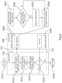
- Fig. 5 illustrates synchronization of a FPGA partition 110 utilizing the synchronizer module 300 according to embodiments.
- the dashed lines 111 indicates the enforced joined starting line (alignment) of the different partitions when the simulation starts.
- the dashed line 112 indicates the end barrier where the simulation terminates. Between the synchronization points (dashed lines 111, 112) of the FPGA partition 110 and/or of the synchronization module 300 may run freely.
- the FPGA partition 110 starts data processing on the exemplary FPGA partition 110.
- the first step in the execution loop synchronizes with other components (e.g. to achieve the desired alignment).
- the FPGA module 110 asks the synchronizer 300 for how long it is allowed to run and may request an approval of the next time step.
- the synchronizer module 300 provides a time stamp, optionally together with the employed synchronization window 310.
- the synchronizer 300 compares the requested time step request with the timing in other partitions 120, 130, 140 to make sure that all partitions remain in the set synchronization window 310.
- step S532 the synchronizer decides whether the next time step is bigger that the allowed time window (synchronization window 310) or not. If so, at step S533, the next time step is adjusted to the window frame of the synchronization window 310 and, at step S534, the time step is saved and the new time stamp is returned to the requested partition 110. If not, step S533 is skipped and the system goes directly to step S534.
- the FPGA partition 110 sets the FPGA time (at step S513) and, at step S514, converts it into a number of cycles, which are executed at step(s) S515. After execution of the number of cycles, the running simulation of the FPGA partition 110 decides whether or not the simulation can continue (at step S516). The simulation on the FPGA partition 110 will continue until a stop signal is received from the synchronizer at step S535.
- the FPGA partition 110 ends (finishes) the thread at step S518. If not, the simulation continues with reiterating steps S513, S514, S515 and S516 until the simulation shall stop.
- the FPGA module (partition 110) asks the synchronizer 300 for how long it is allowed to run.
- the synchronizer 300 provides a time stamp and the DUT on the FPGA partition 110 may be executed for exactly the number of clock cycles to match the synchronizer time. The DUT execution period may then be blocked. As soon as it ends, the synchronization with other components (other partitions) will be performed again. This process is repeated until the synchronizer 300 stops the simulation.
- the thread is put to sleep and is woken up either by a time update or by an input (e.g. a transaction_package), or by the simulation stop.
- Fig. 6 illustrates a thread synchronization of a virtual platform simulation partition 130 (or partition 140) which may be a so-called SystemC partition providing a software simulation of the corresponding DUT.
- the simulation starts at step S611.
- an initialization is performed, and a scheduler of a kernel of the virtual platform on the partition 130 is executed thereafter, at step S613 (e.g. a delta cycle of the SystemC system).
- the scheduler decides whether the simulation time has finished or not. If so, the simulation exits at step S617 which may be associated with a corresponding (external) stop signal received at step S618.
- step S615 a time alignment is carried out at step S615, which again includes a request to the synchronizer 300 to get an approval for the new time stamp. If this is received, the simulation continues to advance in time at step S616 and the delta cycle is again executed at step S613.
- the time alignment at step S615 is performed similarly to the alignment as carried out for the FPGA partition 110 (see Fig. 5 ).
- the synchronizer 300 compares, at step S631, the requested time step with time steps of the other partitions 110, 120, 140. Thereafter, at step S632 the synchronizer 300 decides whether the next time step is bigger than the allowed time window 310. If so, at step S633, the simulation is set to a sleep until the time stamp is within the allowed synchronization window 310. Thereafter, the new time stamp is saved and returned to the partition 130 at step S634.
- step S633 of placing the simulation to a sleep is bypassed and the simulation goes directly to the return of the new time stamp to the time alignment step S615 of the partition 130.
- This exemplary synchronization of a SystemC partition will ensure correct communication between several parallel-running components (partitions 110, 120, 130, 140).
- an Accelera SystemC kernel may not provide this functionality (Accellera SystemC is a reference implementation of the SystemC language). If, according to embodiments, the SystemC kernel wants to update the current simulation time, it may have the next time step approved by the synchronizer 300.
- the synchronizer 300 keeps the current time of all partitions 110, 120, 130, 140 and a synchronization window 310.
- the conventional Accellera SystemC scheduler may be extended to interact with the synchronizer 300.
- the Synchronizer 300 intervenes in the scheduler loop always before the timestamp is updated at step S616. Then (see step S631) the "desired" timestamp is compared with the current timestamps in the other partitions 110, 120, 140 so that the synchronization window 310 is not violated. If the desired timestamp cannot be reached without violating the synchronization window 310, the thread is put to sleep (at step S633) and woken up again as soon as the timestamp is allowed by the synchronizer 300.
- Fig. 7 illustrates more details of the synchronization flow of the exemplary SystemC partition 130.
- step S712 the simulation starts at step S711, followed by step S712 with an evaluation and an update for the simulation time.
- the next time stamp is received.
- step S714 the system decides whether the simulation time is completed, and no external updates are available. If so, the simulation exits at step S722. If not, at step S715, the simulation decides whether the next time stamp is larger than the current time. If so, at step S716, the simulation again carries out a time alignment and, if not, the simulation proceeds with step S719 (to process the timed event).
- This time alignment S716 includes again, at step S731, a comparison of the time stamp request with the timing in other threads.
- the synchronizer 300 decides if the next time step is bigger than the allowed time window 310. If so, at step S733, the simulation is placed a sleep until the time stamp can be reached or until a transaction from another thread arrives. Thereafter, at step S734, the time step is saved and returned as a new time stamp to the thread. If the next time step is not bigger than the allowed time window at step S732, the step of placing the simulation at a sleep at step S733 is bypassed and the new time stamp is immediately returned to the simulation.
- step S717 the time step is set and then, at step S718, the simulation decides whether any event is to be processed at the current time. If not, the simulation returns to step S713, and if so, the simulation processes, at step S719, the further events. Thereafter, at step S720, the simulation decides whether or not further runnable processes are available. If no runnable processes are available, the simulation completes at step S721. When there are still runnable processes, the simulation returns to step S713 or to step S718.
- step S721 the simulation exits at step S722 if the simulation time is completed. If not, the simulation proceeds with step S712.
- an Accellera SystemC scheduler is extended to interact with Synchronizer 300 as set out before.
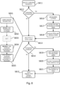
- Fig. 8 illustrates an integration of the FPGA partition 110 and an execution flow.
- the term FIFO 422 includes a corresponding controller that manage the data buffering.
- the FIFO 422 is checked for outstanding input transactions from other partitions 120, 130, 140 to the DUT on the exemplary FPGA partition 110. If, at step S812, it is decided that there are any, they are transferred to the FPGA memory and the FPGA is adapted to locate the corresponding memory. Concretely, this is done by allocating buffer space on the FPGA partition 110 (at step S816) and to serialize and to write transactions to the buffer space (at step S817).
- the FPGA 110 is configured to have the address of the buffer space (step S818) available.
- the FPGA 110 is informed, at step S813, about the amount of cycles it may run. Internally (see steps S831 to S835), the FPGA 110 will then update its expected simulation time (at step S831) and read the transactions from the memory (at step S832). While the FPGA runs until its simulation time matches the expected simulation time, drivers execute the transactions by applying the corresponding input signal transitions to the DUT (at step S833). Then, at step S834, monitoring devices watch the DUT's output signals to capture the transitions and convert them back into transactions. These transactions from the DUT are sent back to the Backplane (see next section). Monitored transactions are also written to a Ring Buffer (at step S834). When the current simulation time of the FPGA 110 reaches the expected simulation time it notifies the host about the completion of the task and returns the number of monitored transactions and their position in the Ring Buffer (at step S835).
- the FPGA 110 verifies whether transactions are monitored. If so, at step S819, transactions are read from the buffer space (e.g. ring buffer, e.g. a direct memory access, DMA, buffer). At step S820, the transactions are converted from CBOR (concise binary object representation) to TLM (transaction level modeling). At step 821, the transactions are sent to another partition 120, 130, 140 via FIFO. Therefore, the host reads these output transactions from the FPGA memory and sends them to the respective partition.
- the buffer space e.g. ring buffer, e.g. a direct memory access, DMA, buffer.
- CBOR concise binary object representation
- TLM transaction level modeling
- step S815 the method returns to signal the completion of the task to the backplane 200.
- the integration of the FPGA partitions 110, 120 is implemented as follows. First, there are two types of information which are to be exchanged between the infrastructure and the FPGA partitions 110, 120:
- Data transactions from other partitions 130, 140 to the DUT on the FPGA partition 110 are not directly sent, but instead are stored in a buffer 422 (e.g. a multiple producer single consumer, MPSC, FIFO as described with Fig. 3A, 3B ). From there the data will be transferred to the FPGA partitions 110, 120 in batches. According to embodiments, this may be done each time the respective FPGA partition 110, 120 gets permission from the synchronizer 300 to continue the DUT execution (zoom-in into the "execute" block in Fig. 5 ).
- a buffer 422 e.g. a multiple producer single consumer, MPSC, FIFO as described with Fig. 3A, 3B .
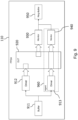
- Fig. 9 shows an exemplary architecture for an FPGA partition 110.
- the partition 110 includes a buffer 911, two drivers 912, 913 (or more), a device under test 920 (hardware implemented by the FPGA), two monitors 930, 940 (or more), and an exemplary ring buffer 950.
- the depicted hardware components may be utilized in the aforementioned methods.
- Transactions can either be generated by other partitions 120, 130, 140 and consumed by the DUT 920 on the FPGA 110 or generated by the DUT 920 and consumed by the other partitions 120, 130, 140. Transactions generated by other partitions 120, 130, 140 will be handled by one of the drivers 912, 913 which converts them into signal transitions forwarded to the DUT 92 0 .
- the monitors 930, 940 watches the outgoing signals and generates output transaction objects accordingly.
- a driver 912, 913 is created.
- a monitor 930, 940 is created.
- Some interfaces (e.g. AXI) can consume as well as produce transactions.
- a driver 913 and a monitor 940 are created. Together they may form an agent 960.
- Embodiments provide at least the following advantages.
- the method and the system allow a parallel simulation of large systems divided among several FPGAs and/or software threads.
- This infrastructure enables a parallel simulation of RTL on FPGA and Virtual Platforms on a host.
- ASIC application specific integrated circuit
- the parallel infrastructure can be run on-premise, but optionally also in a cloud (remote server).
Landscapes
- Engineering & Computer Science (AREA)
- Theoretical Computer Science (AREA)
- Computer Hardware Design (AREA)
- Physics & Mathematics (AREA)
- Software Systems (AREA)
- General Engineering & Computer Science (AREA)
- General Physics & Mathematics (AREA)
- Evolutionary Computation (AREA)
- Geometry (AREA)
- Management, Administration, Business Operations System, And Electronic Commerce (AREA)
Priority Applications (2)
| Application Number | Priority Date | Filing Date | Title |
|---|---|---|---|
| EP22202781.5A EP4357964A1 (fr) | 2022-10-20 | 2022-10-20 | Appareil et procédé de synchronisation de participants à une simulation |
| US18/382,086 US12405842B2 (en) | 2022-10-20 | 2023-10-20 | Apparatus and method for synchronizing participants of a simulation |
Applications Claiming Priority (1)
| Application Number | Priority Date | Filing Date | Title |
|---|---|---|---|
| EP22202781.5A EP4357964A1 (fr) | 2022-10-20 | 2022-10-20 | Appareil et procédé de synchronisation de participants à une simulation |
Publications (1)
| Publication Number | Publication Date |
|---|---|
| EP4357964A1 true EP4357964A1 (fr) | 2024-04-24 |
Family
ID=83902942
Family Applications (1)
| Application Number | Title | Priority Date | Filing Date |
|---|---|---|---|
| EP22202781.5A Pending EP4357964A1 (fr) | 2022-10-20 | 2022-10-20 | Appareil et procédé de synchronisation de participants à une simulation |
Country Status (2)
| Country | Link |
|---|---|
| US (1) | US12405842B2 (fr) |
| EP (1) | EP4357964A1 (fr) |
Families Citing this family (1)
| Publication number | Priority date | Publication date | Assignee | Title |
|---|---|---|---|---|
| CN119544728B (zh) * | 2024-11-27 | 2025-12-19 | 中国农业银行股份有限公司 | 一种数据同步方法及相关装置 |
Citations (1)
| Publication number | Priority date | Publication date | Assignee | Title |
|---|---|---|---|---|
| US11327790B1 (en) * | 2018-07-03 | 2022-05-10 | Synopsys, Inc. | Event-level parallel simulation using dynamic synchronization |
Family Cites Families (19)
| Publication number | Priority date | Publication date | Assignee | Title |
|---|---|---|---|---|
| JP3175757B2 (ja) * | 1996-08-13 | 2001-06-11 | 日本電気株式会社 | デバッグシステム |
| WO2002056541A2 (fr) * | 2000-10-27 | 2002-07-18 | Tekelec Us | Procedes et systemes d'essai de composants de reseaux de communications |
| US20020169863A1 (en) * | 2001-05-08 | 2002-11-14 | Robert Beckwith | Multi-client to multi-server simulation environment control system (JULEP) |
| US20080091403A1 (en) * | 2006-10-16 | 2008-04-17 | Harrison Gregory A | Large Training System Simulation Using Dynamic Network Entities |
| KR101522477B1 (ko) * | 2010-08-20 | 2015-05-21 | 인터내셔널 비지네스 머신즈 코포레이션 | 시뮬레이션 방법, 시스템 및 프로그램 |
| US8903893B2 (en) * | 2011-11-15 | 2014-12-02 | International Business Machines Corporation | Diagnostic heartbeating in a distributed data processing environment |
| US20150019193A1 (en) * | 2013-07-14 | 2015-01-15 | Qualcomm Technologies, Inc. | Verification using generic protocol adapters |
| US9529662B1 (en) * | 2015-07-31 | 2016-12-27 | Netapp, Inc. | Dynamic rule-based automatic crash dump analyzer |
| US10198474B2 (en) * | 2016-01-19 | 2019-02-05 | Quest Software Inc. | Delaying one or more searches to cause multiple searches to load and evaluate segments together |
| US10850199B2 (en) * | 2018-04-04 | 2020-12-01 | UberGeekGames LLC | Scripting engine and implementations |
| US20200057707A1 (en) * | 2018-08-17 | 2020-02-20 | Alibaba Group Holding Limited | Methods and apparatus for full-system performance simulation |
| CN112204529B (zh) * | 2018-11-16 | 2025-08-22 | 谷歌有限责任公司 | 用于复杂系统分析的实时交互式仿真的影子追踪 |
| US11321507B1 (en) * | 2019-04-12 | 2022-05-03 | Avery Design Systems, Inc. | System and method for accurate X handling using logic and symbolic cosimulation |
| CN111641470B (zh) * | 2020-05-08 | 2022-08-02 | 哈尔滨工程大学 | 一种分布式仿真的时间一致性同步方法 |
| US20200272533A1 (en) * | 2020-05-14 | 2020-08-27 | Intel Corporation | Detecting memory mismatch between lockstep systems using a memory signature |
| US11813748B2 (en) * | 2020-10-13 | 2023-11-14 | Google Llc | Simulating multiple robots in virtual environments |
| CA3146521C (fr) * | 2021-02-02 | 2026-01-20 | The Boeing Company | Systeme et methode de minutage pour une machine virtuelle ayant de multiples coeurs de processeur virtuels |
| US20220374260A1 (en) * | 2021-05-21 | 2022-11-24 | Samsung Electronics Co., Ltd. | Systems, methods, and apparatus for coordinating computation systems |
| US20230076849A1 (en) * | 2021-09-07 | 2023-03-09 | Yohana Llc | Systems and methods for implementing dynamic interfacing in task-facilitation services |
-
2022
- 2022-10-20 EP EP22202781.5A patent/EP4357964A1/fr active Pending
-
2023
- 2023-10-20 US US18/382,086 patent/US12405842B2/en active Active
Patent Citations (1)
| Publication number | Priority date | Publication date | Assignee | Title |
|---|---|---|---|---|
| US11327790B1 (en) * | 2018-07-03 | 2022-05-10 | Synopsys, Inc. | Event-level parallel simulation using dynamic synchronization |
Non-Patent Citations (3)
| Title |
|---|
| JEFF S STEINMAN: "Interactive SPEEDES", SIMULATION SYMPOSIUM, 1991., PROCEEDINGS OF THE 24TH ANNUAL NEW ORLEANS, LA, USA 1-5 APRIL 1991, LOS ALAMITOS, CA, USA,IEEE COMPUT. SOC, US, 1 April 1991 (1991-04-01), pages 149 - 158, XP058161350, ISBN: 978-0-8186-2169-7 * |
| SEOK MOON GI ET AL: "An HLA-Based Formal Co-Simulation Approach for Rapid Prototyping of Heterogeneous Mixed-Signal SoCs", IEICE TRANSACTIONS ON FUNDAMENTALS OF ELECTRONICS,COMMUNICATIONS AND COMPUTER SCIENCES., vol. E100.A, no. 7, 1 January 2017 (2017-01-01), JP, pages 1 - 10, XP093037272, ISSN: 0916-8508, Retrieved from the Internet <URL:https://www.researchgate.net/profile/Moon-Gi-Seok/publication/318056622_An_HLA-Based_Formal_Co-Simulation_Approach_for_Rapid_Prototyping_of_Heterogeneous_Mixed-Signal_SoCs/links/5e5df4ed92851cefa1d6c3f2/An-HLA-Based-Formal-Co-Simulation-Approach-for-Rapid-Prototyping-of-Heterogeneous-Mixed-Signal-So> [retrieved on 20230404], DOI: 10.1587/transfun.E100.A.1374 * |
| WILSEY PHILIP A: "Time Warp Simulation on Multi-Core Platforms", 2019 WINTER SIMULATION CONFERENCE (WSC), IEEE, 8 December 2019 (2019-12-08), pages 1454 - 1468, XP033718255, DOI: 10.1109/WSC40007.2019.9004880 * |
Also Published As
| Publication number | Publication date |
|---|---|
| US20240231956A9 (en) | 2024-07-11 |
| US12405842B2 (en) | 2025-09-02 |
| US20240134718A1 (en) | 2024-04-25 |
Similar Documents
| Publication | Publication Date | Title |
|---|---|---|
| US10169513B2 (en) | Method and system for designing FPGA based on hardware requirements defined in source code | |
| EP3105761B1 (fr) | Logique d'interface de couche physique de mémoire pour générer des instructions de mémoire vive dynamique (dram) avec retards programmables | |
| US7472055B2 (en) | Method and system for deterministic control of an emulation | |
| KR100483636B1 (ko) | 에뮬레이션및시뮬레이션을이용한설계검증방법및장치 | |
| CN100573535C (zh) | 模拟系统以及用于模拟和验证控制系统的计算机实施的方法 | |
| US7440885B2 (en) | Method and system for deterministic control of an emulation | |
| US20100100704A1 (en) | Integrated circuit incorporating an array of interconnected processors executing a cycle-based program | |
| US9935637B2 (en) | Systems and methods for FPGA development and operation | |
| CN116711279A (zh) | 用于多个虚拟ecu的模拟和测试的系统和方法 | |
| CN118227527A (zh) | Sdram控制器子系统的源同步分区 | |
| EP4357964A1 (fr) | Appareil et procédé de synchronisation de participants à une simulation | |
| US7472054B2 (en) | Method and system for deterministic control of an emulation | |
| Betti et al. | Real-time I/O management system with COTS peripherals | |
| CN112416053B (zh) | 多核架构的同步信号产生电路、芯片和同步方法及装置 | |
| US20050055190A1 (en) | Circuit operation verification device and method | |
| Rutishauser et al. | A system to provide deterministic flight software operation and maximize multicore processing performance: The safe and precise landing–integrated capabilities evolution (splice) datapath | |
| JP2000215226A (ja) | 論理検証装置 | |
| CN116745750A (zh) | 图形处理器的共享控制总线 | |
| JPH08263526A (ja) | シミュレーション装置 | |
| US20040225490A1 (en) | Device for emulating one or more integrated-circuit chips | |
| US20260010700A1 (en) | Methods and systems for clock control logic cloning for mesh clock | |
| JP4743427B2 (ja) | 回路動作検証方法 | |
| Abdi et al. | Hardware-dependent software synthesis for many-core embedded systems | |
| Chandhoke et al. | A model-based methodology of programming cyber-physical systems | |
| KR20170055964A (ko) | 태스크의 배분 경로를 결정하는 방법, 디바이스 및 시스템 |
Legal Events
| Date | Code | Title | Description |
|---|---|---|---|
| PUAI | Public reference made under article 153(3) epc to a published international application that has entered the european phase |
Free format text: ORIGINAL CODE: 0009012 |
|
| STAA | Information on the status of an ep patent application or granted ep patent |
Free format text: STATUS: THE APPLICATION HAS BEEN PUBLISHED |
|
| AK | Designated contracting states |
Kind code of ref document: A1 Designated state(s): AL AT BE BG CH CY CZ DE DK EE ES FI FR GB GR HR HU IE IS IT LI LT LU LV MC ME MK MT NL NO PL PT RO RS SE SI SK SM TR |
|
| STAA | Information on the status of an ep patent application or granted ep patent |
Free format text: STATUS: REQUEST FOR EXAMINATION WAS MADE |
|
| 17P | Request for examination filed |
Effective date: 20241023 |
|
| RBV | Designated contracting states (corrected) |
Designated state(s): AL AT BE BG CH CY CZ DE DK EE ES FI FR GB GR HR HU IE IS IT LI LT LU LV MC ME MK MT NL NO PL PT RO RS SE SI SK SM TR |