EP4358215A1 - Elektrodenpolstück und herstellungsverfahren dafür, sekundärbatterie, batteriemodul und batteriepack - Google Patents
Elektrodenpolstück und herstellungsverfahren dafür, sekundärbatterie, batteriemodul und batteriepack Download PDFInfo
- Publication number
- EP4358215A1 EP4358215A1 EP22918245.6A EP22918245A EP4358215A1 EP 4358215 A1 EP4358215 A1 EP 4358215A1 EP 22918245 A EP22918245 A EP 22918245A EP 4358215 A1 EP4358215 A1 EP 4358215A1
- Authority
- EP
- European Patent Office
- Prior art keywords
- electrode plate
- active material
- insulating strip
- slurry
- material layer
- Prior art date
- Legal status (The legal status is an assumption and is not a legal conclusion. Google has not performed a legal analysis and makes no representation as to the accuracy of the status listed.)
- Pending
Links
Images



Classifications
-
- H—ELECTRICITY
- H01—ELECTRIC ELEMENTS
- H01M—PROCESSES OR MEANS, e.g. BATTERIES, FOR THE DIRECT CONVERSION OF CHEMICAL ENERGY INTO ELECTRICAL ENERGY
- H01M4/00—Electrodes
- H01M4/02—Electrodes composed of, or comprising, active material
- H01M4/62—Selection of inactive substances as ingredients for active masses, e.g. binders, fillers
- H01M4/628—Inhibitors, e.g. gassing inhibitors, corrosion inhibitors
-
- H—ELECTRICITY
- H01—ELECTRIC ELEMENTS
- H01M—PROCESSES OR MEANS, e.g. BATTERIES, FOR THE DIRECT CONVERSION OF CHEMICAL ENERGY INTO ELECTRICAL ENERGY
- H01M4/00—Electrodes
- H01M4/02—Electrodes composed of, or comprising, active material
- H01M4/36—Selection of substances as active materials, active masses, active liquids
- H01M4/48—Selection of substances as active materials, active masses, active liquids of inorganic oxides or hydroxides
- H01M4/52—Selection of substances as active materials, active masses, active liquids of inorganic oxides or hydroxides of nickel, cobalt or iron
- H01M4/525—Selection of substances as active materials, active masses, active liquids of inorganic oxides or hydroxides of nickel, cobalt or iron of mixed oxides or hydroxides containing iron, cobalt or nickel for inserting or intercalating light metals, e.g. LiNiO2, LiCoO2 or LiCoOxFy
-
- H—ELECTRICITY
- H01—ELECTRIC ELEMENTS
- H01M—PROCESSES OR MEANS, e.g. BATTERIES, FOR THE DIRECT CONVERSION OF CHEMICAL ENERGY INTO ELECTRICAL ENERGY
- H01M10/00—Secondary cells; Manufacture thereof
- H01M10/05—Accumulators with non-aqueous electrolyte
- H01M10/052—Li-accumulators
- H01M10/0525—Rocking-chair batteries, i.e. batteries with lithium insertion or intercalation in both electrodes; Lithium-ion batteries
-
- H—ELECTRICITY
- H01—ELECTRIC ELEMENTS
- H01M—PROCESSES OR MEANS, e.g. BATTERIES, FOR THE DIRECT CONVERSION OF CHEMICAL ENERGY INTO ELECTRICAL ENERGY
- H01M10/00—Secondary cells; Manufacture thereof
- H01M10/42—Methods or arrangements for servicing or maintenance of secondary cells or secondary half-cells
-
- H—ELECTRICITY
- H01—ELECTRIC ELEMENTS
- H01M—PROCESSES OR MEANS, e.g. BATTERIES, FOR THE DIRECT CONVERSION OF CHEMICAL ENERGY INTO ELECTRICAL ENERGY
- H01M4/00—Electrodes
- H01M4/02—Electrodes composed of, or comprising, active material
- H01M4/04—Processes of manufacture in general
-
- H—ELECTRICITY
- H01—ELECTRIC ELEMENTS
- H01M—PROCESSES OR MEANS, e.g. BATTERIES, FOR THE DIRECT CONVERSION OF CHEMICAL ENERGY INTO ELECTRICAL ENERGY
- H01M4/00—Electrodes
- H01M4/02—Electrodes composed of, or comprising, active material
- H01M4/04—Processes of manufacture in general
- H01M4/0402—Methods of deposition of the material
- H01M4/0404—Methods of deposition of the material by coating on electrode collectors
-
- H—ELECTRICITY
- H01—ELECTRIC ELEMENTS
- H01M—PROCESSES OR MEANS, e.g. BATTERIES, FOR THE DIRECT CONVERSION OF CHEMICAL ENERGY INTO ELECTRICAL ENERGY
- H01M4/00—Electrodes
- H01M4/02—Electrodes composed of, or comprising, active material
- H01M4/13—Electrodes for accumulators with non-aqueous electrolyte, e.g. for lithium-accumulators; Processes of manufacture thereof
-
- H—ELECTRICITY
- H01—ELECTRIC ELEMENTS
- H01M—PROCESSES OR MEANS, e.g. BATTERIES, FOR THE DIRECT CONVERSION OF CHEMICAL ENERGY INTO ELECTRICAL ENERGY
- H01M4/00—Electrodes
- H01M4/02—Electrodes composed of, or comprising, active material
- H01M4/13—Electrodes for accumulators with non-aqueous electrolyte, e.g. for lithium-accumulators; Processes of manufacture thereof
- H01M4/131—Electrodes based on mixed oxides or hydroxides, or on mixtures of oxides or hydroxides, e.g. LiCoOx
-
- H—ELECTRICITY
- H01—ELECTRIC ELEMENTS
- H01M—PROCESSES OR MEANS, e.g. BATTERIES, FOR THE DIRECT CONVERSION OF CHEMICAL ENERGY INTO ELECTRICAL ENERGY
- H01M4/00—Electrodes
- H01M4/02—Electrodes composed of, or comprising, active material
- H01M4/13—Electrodes for accumulators with non-aqueous electrolyte, e.g. for lithium-accumulators; Processes of manufacture thereof
- H01M4/139—Processes of manufacture
-
- H—ELECTRICITY
- H01—ELECTRIC ELEMENTS
- H01M—PROCESSES OR MEANS, e.g. BATTERIES, FOR THE DIRECT CONVERSION OF CHEMICAL ENERGY INTO ELECTRICAL ENERGY
- H01M4/00—Electrodes
- H01M4/02—Electrodes composed of, or comprising, active material
- H01M4/13—Electrodes for accumulators with non-aqueous electrolyte, e.g. for lithium-accumulators; Processes of manufacture thereof
- H01M4/139—Processes of manufacture
- H01M4/1391—Processes of manufacture of electrodes based on mixed oxides or hydroxides, or on mixtures of oxides or hydroxides, e.g. LiCoOx
-
- H—ELECTRICITY
- H01—ELECTRIC ELEMENTS
- H01M—PROCESSES OR MEANS, e.g. BATTERIES, FOR THE DIRECT CONVERSION OF CHEMICAL ENERGY INTO ELECTRICAL ENERGY
- H01M4/00—Electrodes
- H01M4/02—Electrodes composed of, or comprising, active material
- H01M4/62—Selection of inactive substances as ingredients for active masses, e.g. binders, fillers
-
- H—ELECTRICITY
- H01—ELECTRIC ELEMENTS
- H01M—PROCESSES OR MEANS, e.g. BATTERIES, FOR THE DIRECT CONVERSION OF CHEMICAL ENERGY INTO ELECTRICAL ENERGY
- H01M4/00—Electrodes
- H01M4/02—Electrodes composed of, or comprising, active material
- H01M4/62—Selection of inactive substances as ingredients for active masses, e.g. binders, fillers
- H01M4/621—Binders
- H01M4/622—Binders being polymers
-
- H—ELECTRICITY
- H01—ELECTRIC ELEMENTS
- H01M—PROCESSES OR MEANS, e.g. BATTERIES, FOR THE DIRECT CONVERSION OF CHEMICAL ENERGY INTO ELECTRICAL ENERGY
- H01M4/00—Electrodes
- H01M4/02—Electrodes composed of, or comprising, active material
- H01M4/62—Selection of inactive substances as ingredients for active masses, e.g. binders, fillers
- H01M4/621—Binders
- H01M4/622—Binders being polymers
- H01M4/623—Binders being polymers fluorinated polymers
-
- H—ELECTRICITY
- H01—ELECTRIC ELEMENTS
- H01M—PROCESSES OR MEANS, e.g. BATTERIES, FOR THE DIRECT CONVERSION OF CHEMICAL ENERGY INTO ELECTRICAL ENERGY
- H01M4/00—Electrodes
- H01M4/02—Electrodes composed of, or comprising, active material
- H01M4/64—Carriers or collectors
- H01M4/66—Selection of materials
-
- H—ELECTRICITY
- H01—ELECTRIC ELEMENTS
- H01M—PROCESSES OR MEANS, e.g. BATTERIES, FOR THE DIRECT CONVERSION OF CHEMICAL ENERGY INTO ELECTRICAL ENERGY
- H01M4/00—Electrodes
- H01M4/02—Electrodes composed of, or comprising, active material
- H01M4/64—Carriers or collectors
- H01M4/66—Selection of materials
- H01M4/665—Composites
- H01M4/667—Composites in the form of layers, e.g. coatings
-
- H—ELECTRICITY
- H01—ELECTRIC ELEMENTS
- H01M—PROCESSES OR MEANS, e.g. BATTERIES, FOR THE DIRECT CONVERSION OF CHEMICAL ENERGY INTO ELECTRICAL ENERGY
- H01M4/00—Electrodes
- H01M4/02—Electrodes composed of, or comprising, active material
- H01M2004/021—Physical characteristics, e.g. porosity, surface area
-
- H—ELECTRICITY
- H01—ELECTRIC ELEMENTS
- H01M—PROCESSES OR MEANS, e.g. BATTERIES, FOR THE DIRECT CONVERSION OF CHEMICAL ENERGY INTO ELECTRICAL ENERGY
- H01M4/00—Electrodes
- H01M4/02—Electrodes composed of, or comprising, active material
- H01M2004/026—Electrodes composed of, or comprising, active material characterised by the polarity
- H01M2004/028—Positive electrodes
-
- H—ELECTRICITY
- H01—ELECTRIC ELEMENTS
- H01M—PROCESSES OR MEANS, e.g. BATTERIES, FOR THE DIRECT CONVERSION OF CHEMICAL ENERGY INTO ELECTRICAL ENERGY
- H01M2220/00—Batteries for particular applications
- H01M2220/20—Batteries in motive systems, e.g. vehicle, ship, plane
-
- Y—GENERAL TAGGING OF NEW TECHNOLOGICAL DEVELOPMENTS; GENERAL TAGGING OF CROSS-SECTIONAL TECHNOLOGIES SPANNING OVER SEVERAL SECTIONS OF THE IPC; TECHNICAL SUBJECTS COVERED BY FORMER USPC CROSS-REFERENCE ART COLLECTIONS [XRACs] AND DIGESTS
- Y02—TECHNOLOGIES OR APPLICATIONS FOR MITIGATION OR ADAPTATION AGAINST CLIMATE CHANGE
- Y02E—REDUCTION OF GREENHOUSE GAS [GHG] EMISSIONS, RELATED TO ENERGY GENERATION, TRANSMISSION OR DISTRIBUTION
- Y02E60/00—Enabling technologies; Technologies with a potential or indirect contribution to GHG emissions mitigation
- Y02E60/10—Energy storage using batteries
Definitions
- the present application relates to the technical field of lithium batteries, and particularly relates to an electrode plate, a method for preparing the same, a secondary battery, a battery module, and a battery pack.
- secondary batteries lithium-ion batteries are widely used in products, such as electric vehicles and electronic devices.
- an object of the present application is to improve width consistency of an active material layer in an electrode plate, thus reducing a defective rate of the electrode plate.
- the present application provides an electrode plate, a secondary battery, a battery module, a battery pack, and an electrical apparatus.
- a first aspect of the present application provides an electrode plate, comprising a main body region and an isolation region, where the isolation region is arranged on both sides of the main body region along a width direction of the electrode plate, the isolation region is provided with an insulating strip coating, and the main body region is provided with an active material layer.
- An outer edge of the active material layer is confined to a junction between the main body region and the isolation region, and a contact angle between a slurry forming the active material layer and the insulating strip coating is more than 90°, and is optionally more than 125°.
- the large contact angle between the slurry of the active material layer and the insulating strip coating reduces climbing and migration between the active material and the insulating strip coating, and improves a problem of diffusion of the active material slurry along the width direction of the electrode plate, thereby effectively improving the width consistency of the active material layer in the electrode plate, reducing a risk of misalignment caused by inconsistent widths of active material layers on both sides of the electrode plate, and reducing the defective rate of the electrode plate.
- the insulating strip coating comprises a functional material.
- the slurry forming the active material layer is a slurry of an aqueous system, and the insulating strip coating comprises a hydrophobic material; or the slurry forming the active material layer is a slurry of an oily system, and the insulating strip coating comprises an oleophobic material, thereby inhibiting diffusion of the aqueous active material slurry or the oily active material slurry to an edge of the electrode plate.
- the hydrophobic material comprises at least one of polyolefin, polycarbonate, polyamide, and polyacrylonitrile.
- the above hydrophobic material has good hydrophobic performance.
- the oleophobic material comprises at least one of polytetrafluoroethylene and nanometer SiO 2 .
- the above oleophobic material has good oleophobic performance.
- a thickness H 1 of the insulating strip coating is less than a thickness H 2 of the active material layer, thereby enabling the isolation region to have a good inhibitory effect on the diffusion of the active material layer, and resulting in an electrode plate with good quality.
- the thickness H 1 of the insulating strip coating is from 5 ⁇ m to 30 ⁇ m, and the thickness H 2 of the active material layer is from 30 ⁇ m to 150 ⁇ m, thereby enabling the insulating strip coating to have a good inhibitory effect on the diffusion of the active material layer, and resulting in an electrode plate with good quality.
- the thickness H 1 of the insulating strip coating and the thickness Hz of the active material layer satisfy: 1/5 ⁇ H 1 :H 2 ⁇ 2/3, thereby reducing a risk of crushing the electrode plate due to too large thickness H 1 of the insulating strip coating during cold pressing, and contributing to further improvement of the quality of the electrode plate.
- a width of the insulating strip coating is from 1 mm to 20 mm, so that an electrode plate with good quality can be obtained.
- a second aspect of the present application further provides a method for preparing an electrode plate, including steps of: preparation of an insulating strip coating: mixing a functional material, an insulating material, and a first binder, then adding a first solvent into the mixture, to form a first slurry, coating the first slurry on both sides of a surface of a current collector along a length direction of the current collector, and drying to form two insulating strip coatings; where a surface of the current collector uncoated with the first slurry between the two insulating strip coatings forms a main body region, and the functional material is selected from a hydrophobic material or an oleophobic material; and preparation of an active material layer: mixing an electrode active material, a conductive agent, and a second binder, then adding a second solvent into the mixture, to form a second slurry; coating the second slurry on the surface of the main body region, and drying to form the active material layer.
- a contact angle between the second slurry and the insulating strip coating
- the preparation method in the present application has the advantages of simple preparation process and extensive sources of functional materials, is suitable for large-scale production, and is conducive to reducing production costs.
- a percentage mass content of the functional material is from 40% to 70%, a percentage mass content of the insulating material is from 20% to 30%, and a percentage mass content of the first binder is from 10% to 30%.
- the contents of the functional material, the insulating material, the first binder, and the first solvent are synergistically regulated to be within the above ranges, thereby enabling the insulating strip coating to have a good inhibitory effect on the diffusion of the active material layer.
- the functional material is selected from a hydrophobic material, the first solvent is selected from an oily solvent, and the second solvent is selected from an aqueous solvent; or the functional material is selected from an oleophobic material, the first solvent is selected from an aqueous solvent, and the second solvent is selected from an oily solvent.
- the aqueous solvent is selected from at least one of deionized water, ethylene glycol, and ethanol; and the oily solvent is selected from at least one of N-methyl pyrrolidone, N-dimethylformamide, and dimethyl sulfoxide.
- the first binder and the second binder each independently comprise polyvinylidene fluoride or styrene butadiene rubber.
- the above binder has good interface bonding performance.
- the insulating material comprises at least one of aluminum oxide and boehmite.
- the above insulating material has outstanding insulation characteristics, thereby enabling the insulating strip coating to have outstanding insulation performance, and improving the performance of the electrode plate.
- a third aspect of the present application provides a secondary battery, comprising the electrode plate in the first aspect of the present application.
- a fourth aspect of the present application provides a battery module, comprising the secondary battery in the third aspect of the present application.
- a fifth aspect of the present application provides a battery pack, comprising the battery module in the fourth aspect of the present application.
- a sixth aspect of the present application provides an electrical apparatus, comprising at least one of the secondary batteries in the third aspect of the present application, the battery module in the fourth aspect of the present application, or the battery pack in the fifth aspect of the present application.
- the beneficial effects of the present application include:
- the present application provides an electrode plate, a method for preparing the same, a secondary battery, a battery module, and a battery pack, the electrode plate comprises a main body region and an isolation region located on both sides of the main body region, where the isolation region is provided with an insulating strip coating, so that an outer edge of an active material layer is confined to a junction between the main body region and the isolation region. Further, a contact angle between a slurry forming the active material layer and the insulating strip coating is more than 90°.
- the large contact angle reduces climbing and migration between the active material slurry and the insulating strip coating, and improves a problem of diffusion of the active material slurry along a width direction of the electrode plate, thereby effectively improving width consistency of the active material layer in the electrode plate, reducing a risk of misalignment caused by inconsistent widths of active material layers on both sides of the electrode plate, and reducing a defective rate of the electrode plate.
- Ranges disclosed in the present application are defined in the form of lower limits and upper limits, a given range is defined by the selection of a lower limit and an upper limit, and the selected lower and upper limits define boundaries of a particular range.
- a range defined in this manner may be inclusive or exclusive of end values, and may be arbitrarily combined, that is, any lower limit may be combined with any upper limit to form a range. For example, if the ranges of 60-120 and 80-110 are listed for a particular parameter, it is understood that the ranges of 60-110 and 80-120 are also contemplated.
- the numerical range "a-b" represents an abbreviated representation of any combination of real numbers between a to b, where both a and b are real numbers.
- the numerical range "0-5" means that all real numbers between "0-5" have been listed herein, and "0-5" is just an abbreviated representation of the combination of these numerical values.
- a parameter is expressed as an integer greater than or equal to 2, it is equivalent to disclosing that the parameter is, for example, an integer of 2, 3, 4, 5, 6, 7, 8, 9, 10, 11, 12, and the like.
- the method includes steps (a) and (b), which means that the method may include steps (a) and (b) performed sequentially, or may include steps (b) and (a) performed sequentially.
- the reference to the method may further comprise step (c), which means that step (c) may be added to the method in any order, for example, the method may comprise steps (a), (b) and (c), or may comprise steps (a), (c) and (b), or may comprise steps (c), (a) and (b), and so on.
- the terms “include/including” and “comprise/comprising” mentioned in the present application may be open-ended, or may be closed-ended.
- the “including” and “comprising” may mean that other components that are not listed are further included or comprised, or only the listed components are included or comprised.
- the term "or” is inclusive in the present application.
- the phrase “A or B” means “A, B, or both A and B.” More specifically, the condition “A or B” is satisfied under any one of the following conditions: A is true (or present) and B is false (or absent); A is false (or absent) and B is true (or present); or both A and B are true (or present).
- an active material slurry will diffuse outward along a width direction of an electrode plate of an existing secondary battery, which may be due to occurrence of a deviation of a width of an active material layer on a side A and a side B of an electrode when the active material slurry is coated on a surface of the current collector from a design width. After the width of the side A and the side B of the electrode plate deviates from the design width, the side A and the side B are more likely to be misaligned, thereby increasing a defective rate of the electrode plate.
- an isolation region is arranged on both sides of a main body region (a region where the active material layer is provided) of the electrode plate, and the isolation region is provided with an insulating strip coating, so that an outer edge of the active material layer is confined to a junction between the main body region and the isolation region.
- the present application provides an electrode plate, a method for preparing the same, a secondary battery, a battery module, and a battery pack.
- the present application provides an electrode plate.
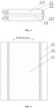
- the electrode plate comprises a main body region 11 and an isolation region 12, where the isolation region 12 is arranged on both sides of the main body region 11 along a width direction of the electrode plate, the isolation region 12 is provided with an insulating strip coating 121, and the main body region 11 is provided with an active material layer 111.
- An outer edge of the active material layer 111 is confined to a junction between the main body region 11 and the isolation region 12, and a contact angle between a slurry forming the active material layer 111 and the insulating strip coating 121 is more than 90°, and is optionally more than 125°.
- the main body region 11 refers to a main part of a main body of the electrode plate, and the main body region 11 is usually provided with an active material layer 111.
- the active material layer 111 may be coated on the surface of the current collector in the main body region 11;
- the isolation region 12 refers to parts arranged along the width direction of the electrode plate and located on both sides of the main body region 11 respectively, and the isolation region 12 is provided with the insulating strip coating 121.
- the electrode plate in the present application may include a positive electrode plate and/or a negative electrode plate.
- the electrode plate may be coated on a single side or may be coated on both sides.
- the active material layer 111 and the insulating strip coating 121 may be arranged on a surface of the current collector 14; and referring to Fig. 3 , in another example, when the electrode plate is coated on both sides, the active material layer 111 and the insulating strip coating 121 may be arranged on both surfaces of the current collector 14.
- the electrode plate in the present application comprises a main body region and an isolation region located on both sides of the main body region, where the isolation region is provided with an insulating strip coating, so that an outer edge of an active material layer is confined to a junction between the main body region and the isolation region.
- a contact angle between a slurry forming the active material layer and the insulating strip coating is more than 90°, to improve a problem of diffusion of the active material slurry along a width direction of the electrode plate, thereby effectively improving width consistency of the active material layer in the electrode plate, reducing a risk of misalignment caused by inconsistent widths of active material layers on both sides of the electrode plate, and reducing a defective rate of the electrode plate.
- the insulating strip coating comprises a functional material.
- the functional material of the present application may include a hydrophobic material or an oleophobic material.
- the slurry forming the active material layer is a slurry of an aqueous system
- the insulating strip coating includes a hydrophobic material, so that there is a large contact angle between the insulating strip coating and the aqueous active material slurry. In this way, when the aqueous active material slurry is in contact with the insulating strip coating, the aqueous active material slurry is difficult to wet the insulating strip coating, thereby inhibiting diffusion of the aqueous active material slurry toward an edge of the electrode plate.
- the slurry forming the active material layer is a slurry of an oily system
- the insulating strip coating includes an oleophobic material, so that there is a large contact angle between the insulating strip coating and the oily active material slurry. In this way, when the oily active material slurry is in contact with the insulating strip coating, the oily active material slurry is difficult to wet the insulating strip coating, thereby inhibiting diffusion of the oily active material slurry toward an edge of the electrode plate.
- the hydrophobic material is not particularly limited in the present application, as long as the objective of the present application can be achieved.
- the hydrophobic material comprises at least one of polyolefin, polycarbonate, polyamide, and polyacrylonitrile.
- the polyolefin is not particularly limited in the present application, as long as the objective of the present application can be achieved, for example, the polyolefin may include polypropylene.
- the oleophobic material is not particularly limited in the present application, as long as the objective of the present application can be achieved.
- the oleophobic material comprises at least one of polytetrafluoroethylene and nanometer SiO 2 .
- a particle size of the nanometer SiO 2 is not particularly limited in the present application, for example, the particle size ranges from 10 nm to 1,000 nm.
- the thickness H 1 of the insulating strip coating 121 is less than the thickness H 2 of the active material layer 111, thus avoiding situations that: too small thickness of the insulating strip coating may affect the inhibitory effect of the isolation region on the diffusion of the active material layer; and too large thickness of the insulating strip coating may affect die-cutting quality of the electrode plate, thus affecting quality of the electrode plate. Therefore, in the present application, the thickness of the insulating strip coating is less than the thickness of the active material layer, thereby enabling the isolation region to have a good inhibitory effect on the diffusion of the active material layer, and resulting in an electrode plate with good quality.
- the thickness H 1 of the insulating strip coating is from 5 ⁇ m to 30 ⁇ m, and the thickness H 2 of the active material layer is from 30 ⁇ m to 150 ⁇ m.
- the thickness H 1 of the insulating strip coating and the thickness H 2 of the active material layer are regulated to be within the above range, thereby enabling the insulating strip coating to have a good inhibitory effect on the diffusion of the active material layer, and resulting in an electrode plate with good quality.
- the width of the active material layer is not particularly limited in the present application, and electrode plates with the active material layer of different widths can be prepared as required. Of course, width design of the active material layer on sides A and B of the electrode plate is usually consistent.
- the thickness H 1 of the insulating strip coating and the thickness H 2 of the active material layer satisfy: 1/5 ⁇ H 1 :H 2 ⁇ 2/3, thereby reducing a risk of crushing the electrode plate due to too large thickness H 1 of the insulating strip coating during cold pressing, and contributing to further improvement of the quality of the electrode plate.
- the width of the insulating strip coating is from 1 mm to 20 mm, thus avoiding situations that: too large width of the insulating strip coating affects a welding effect of a tab, which is not conducive to improvement of yield of the electrode plate, and too small width of the insulating strip coating affects the inhibitory effect of the isolation region on the diffusion of the active material layer.
- a width of the insulating strip coating is regulated to be within the above range, so that an electrode plate with good quality can be obtained.
- the electrode plate in the present application further includes a blank region 13, and the blank region 13 is located on a side of the isolation region 12 away from the main body region 11 along the width direction of the electrode plate.
- the blank region 13 in the present application may refer to a region located at an edge of the electrode plate, a current collector is arranged on a surface of the blank region, and the blank region is capable of reserving space for the tab to gather electrons.
- a width of the blank region is from 10 mm to 60 mm.
- a method for preparing an electrode plate comprising steps of:
- the active material slurry on the surface of the insulating strip coating can still be easily stripped after drying, thereby contributing to improvement of the yield of the electrode plate.
- the functional material is selected from a hydrophobic material or an oleophobic material.
- the first solvent is selected from an oily solvent
- the second solvent is selected from an aqueous solvent.
- an aqueous solvent such as deionized water, is usually used as the second solvent in the negative electrode active material slurry (second slurry), and correspondingly, an oily solvent is used as the first solvent. Based on this, this embodiment can be used in the preparation of a negative electrode plate.
- the first solvent is selected from an aqueous solvent
- the second solvent is selected from an oily solvent.
- an oily solvent such as N-methyl pyrrolidone
- an aqueous solvent is used as the first solvent. Based on this, this embodiment can be used in the preparation of a positive electrode plate.
- a percentage mass content of the functional material is from 40% to 70%, a percentage mass content of the insulating material is from 20% to 30%, and a percentage mass content of the first binder is from 10% to 30%.
- the contents of the functional material, the insulating material, the first binder, and the first solvent are synergistically regulated to be within the above ranges, thereby enabling the insulating strip coating to have a good inhibitory effect on the diffusion of the active material layer.
- the aqueous solvent and the oily solvent are not particularly limited in the present application, as long as the objective of the present application can be achieved.
- the aqueous solvent is selected from at least one of deionized water, ethylene glycol, and ethanol, and has good dispersity for oleophobic materials; and the oily solvent is selected from at least one of N-methyl pyrrolidone, N-dimethylformamide, and dimethyl sulfoxide, and has good dispersity for hydrophobic materials.
- the first binder and the second binder are not particularly limited in the present application, as long as the objective of the present application can be achieved.
- the first binder and the second binder each independently comprise polyvinylidene fluoride or styrene butadiene rubber.
- the above binder has good interface bonding performance.
- the insulating material in the present application includes at least one of aluminum oxide and boehmite, the above insulating material has outstanding insulation characteristics, thereby enabling the insulating strip coating to have outstanding insulation performance, and improving the performance of the electrode plate.
- a particle size of the insulating material is not particularly limited in the present application, as long as the objective of the present application can be achieved.
- a blank region is formed on the surface of the current collector between an outer edge of each insulating strip coating away from the main body region and an edge of a long side of the current collector close thereto.
- the first slurry can be coated at a certain distance from the edge of the long side of the current collector, thereby forming the blank region.
- a secondary battery is provided.
- the secondary battery comprises a positive electrode plate, a negative electrode plate, an electrolyte, and a separator.
- active ions are intercalated and deintercalated back and forth between the positive electrode plate and the negative electrode plate.
- the electrolyte serves to conduct ions between the positive electrode plate and the negative electrode plate.
- the separator is provided between the positive electrode plate and the negative electrode plate, and mainly functions to prevent a short circuit between the positive electrode and the negative electrode, while allowing ions to pass through.
- the positive electrode plate comprises a positive electrode current collector and a positive electrode active material layer arranged on at least one surface of the positive electrode current collector.
- the positive electrode current collector has two surfaces opposite in its own thickness direction, and the positive electrode active material layer is arranged on either one or both of the two opposite surfaces of the positive electrode current collector.
- the positive electrode current collector can be a metal foil or a composite current collector.
- an aluminum foil can be used as the metal foil.
- the composite current collector can comprise a polymer material substrate layer and a metal layer formed on at least one surface of the polymer material substrate layer.
- the composite current collector may be formed by forming a metal material (such as aluminum, aluminum alloy, nickel, nickel alloy, titanium, titanium alloy, silver, and silver alloy) on a polymer material substrate (such as a substrate of polypropylene (PP), polyethylene terephthalate (PET), polybutylene terephthalate (PBT), polystyrene (PS), or polyethylene (PE)).
- PP polypropylene
- PET polyethylene terephthalate
- PBT polybutylene terephthalate
- PS polystyrene
- PE polyethylene
- the positive electrode active material may be a positive electrode active material for batteries well known in the art.
- the positive electrode active material may include at least one of the following materials: a lithium-containing phosphate of olivine structure, a lithium transition metal oxide, and a respective modified compound thereof.
- the present application is not limited to these materials, and other conventional materials useful as positive electrode active materials for batteries can also be used. These positive electrode active materials may be used alone or in combination of two or more thereof.
- lithium transition metal oxides may include, but are not limited to, at least one of a lithium-cobalt oxide (such as LiCoO 2 ), a lithium-nickel oxide (such as LiNiO 2 ), a lithium-manganese oxide (such as LiMnO 2 or LiMn 2 O 4 ), a lithium-nickel-cobalt oxide, a lithium-manganese-cobalt oxide, a lithium-nickel-manganese oxide, a lithium-nickel-cobalt-manganese oxide (such as LiNi 1/3 Co 1/3 Mn 1/3 O 2 (also abbreviated as NCM 333 ), LiNi 0.5 Co 0.2 Mn 0.3 O 2 (also abbreviated as NCM 523 ), LiNi 0.5 Co 0.25 Mn 0.25 O 2 (also abbreviated as NCM 211 ), LiNi 0.6 Co 0.2 Mn 0.2 O 2 (also abbreviated as NCM 622 ), LiNi 0.8 Co 0.1
- lithium-containing phosphate of olivine structure may include, but are not limited to, at least one of lithium iron phosphate (such as LiFePO 4 (also abbreviated as LFP)), a composite material of lithium iron phosphate and carbon, lithium manganese phosphate (such as LiMnPO 4 ), a composite material of lithium manganese phosphate and carbon, lithium iron manganese phosphate, and a composite material of lithium iron manganese phosphate and carbon.
- lithium iron phosphate such as LiFePO 4 (also abbreviated as LFP)
- LiMnPO 4 lithium manganese phosphate
- LiMnPO 4 lithium manganese phosphate and carbon
- the positive electrode active material layer further optionally comprises a binder.
- the binder may comprise at least one of polyvinylidene fluoride (PVDF), polytetrafluoroethylene (PTFE), vinylidene fluoride-tetrafluoroethylene-propylene terpolymer, vinylidene fluoride-hexafluoropropylene-tetrafluoroethylene terpolymer, tetrafluoroethylene-hexafluoropropylene copolymer, and fluoroacrylate resin.
- PVDF polyvinylidene fluoride
- PTFE polytetrafluoroethylene
- PTFE polytetrafluoroethylene
- vinylidene fluoride-hexafluoropropylene-tetrafluoroethylene terpolymer vinylidene fluoride-hexafluoropropylene-tetrafluoroethylene terpolymer
- the positive electrode active material layer further optionally comprises a conductive agent.
- the conductive agent may comprise at least one of superconducting carbon, acetylene black, carbon black, Ketjen black, carbon dot, carbon nanotube, graphene, and carbon nanofiber.
- the positive electrode plate may be prepared by: dispersing the above ingredients, such as the positive electrode active material, the conductive agent, the binder, and any other ingredient, for preparing the positive electrode plate in a solvent (such as N-methyl pyrrolidone) to form a positive electrode slurry; and coating the positive electrode slurry on the positive electrode current collector, drying, and cold pressing, to obtain the positive electrode plate.
- a solvent such as N-methyl pyrrolidone
- the negative electrode plate comprises a negative electrode current collector and a negative electrode active material layer arranged on at least one surface of the negative electrode current collector, the negative electrode active material layer comprising a negative electrode active material.
- the negative electrode current collector has two surfaces opposite in its own thickness direction, and the negative electrode active material layer is arranged on either one or both of the two opposite surfaces of the negative electrode current collector.
- the negative electrode current collector can be a metal foil or a composite current collector.
- a copper foil can be used as the metal foil.
- the composite current collector may comprise a polymer material substrate layer and a metal layer formed on at least one surface of a polymer material substrate.
- the composite current collector may be formed by forming a metal material (such as copper, copper alloy, nickel, nickel alloy, titanium, titanium alloy, silver, and silver alloy) on the polymer material substrate (such as a substrate of polypropylene (PP), polyethylene terephthalate (PET), polybutylene terephthalate (PBT), polystyrene (PS), or polyethylene (PE)).
- PP polypropylene
- PET polyethylene terephthalate
- PBT polybutylene terephthalate
- PS polystyrene
- PE polyethylene
- a negative electrode active material for a battery well-known in the art may be used as the negative electrode active material.
- the negative electrode active material may include at least one of artificial graphite, natural graphite, soft carbon, hard carbon, a silicon-based material, a tin-based material, lithium titanate, and the like.
- the silicon-based material may be at least one selected from the group consisting of elemental silicon, silicon-oxygen compound, silicon-carbon composite, silicon-nitrogen composite, and silicon alloy.
- the tin-based material may be at least one selected from elemental tin, tin-oxygen compound, and tin alloy.
- the present application is not limited to these materials, and other conventional materials useful as negative electrode active materials for batteries can also be used. It is possible to use only one of these negative electrode active materials alone, or to use more than two in combination.
- the negative electrode active material layer further optionally comprises a binder.
- the binder may be selected from at least one of styrene butadiene rubber (SBR), polyacrylic acid (PAA), sodium polyacrylate (PAAS), polyacrylamide (PAM), polyvinyl alcohol (PVA), sodium alginate (SA), polymethacrylic acid (PMAA), and carboxymethyl chitosan (CMCS).
- the negative electrode active material layer further optionally comprises a conductive agent.
- the conductive agent may be selected from at least one of superconducting carbon, acetylene black, carbon black, Ketjen black, carbon dots, carbon nanotubes, graphene, and carbon nanofibers.
- the negative electrode active material layer further optionally comprises other adjuvants, for example, a thickener (such as sodium carboxymethylcellulose (CMC-Na)).
- a thickener such as sodium carboxymethylcellulose (CMC-Na)
- the negative electrode plate may be prepared by: dispersing the above ingredients, such as the negative electrode active material, the conductive agent, the binder, and any other ingredient, for preparing the negative electrode plate in a solvent (such as deionized water) to form a negative electrode slurry; and coating the negative electrode slurry on the negative electrode current collector, drying, and cold pressing, to obtain the negative electrode plate.
- a solvent such as deionized water
- the electrolyte serves to conduct ions between the positive electrode plate and the negative electrode plate.
- the type of the electrolyte is not particularly limited in the present application, and can be selected according to requirements.
- the electrolyte may be in a liquid, gel, or full solid state.
- an electrolyte solution is used as the electrolyte.
- the electrolyte solution comprises an electrolyte salt and a solvent.
- the electrolyte salt may be selected from at least one of lithium hexafluorophosphate, lithium tetrafluoroborate, lithium perchlorate, lithium hexafluoroarsenate, lithium bis(fluorosulfonyl)imide, lithium bis(trifluoromethanesulfonyl)imide, lithium trifluoromethanesulfonate, lithium difluorophosphate, lithium difluoro(oxalato)borate, lithium bis(oxalate)borate, lithium difluoro bis(oxalato)phosphate, and lithium tetrafluoro(oxalato)phosphate.
- the solvent may be selected from at least one of ethylene carbonate, propylene carbonate, ethyl methyl carbonate, diethyl carbonate, dimethyl carbonate, dipropyl carbonate, methyl propyl carbonate, ethyl propyl carbonate, butylene carbonate, fluoroethylene carbonate, methyl formate, methyl acetate, ethyl acetate, propyl acetate, methyl propionate, ethyl propionate, propyl propionate, methyl butyrate, ethyl butyrate, 1,4-butyrolactone, sulfolane, dimethyl sulfone, methyl ethyl sulfone, and diethyl sulfone.
- the electrolyte solution further optionally comprises an additive.
- the additive may include a negative electrode film-forming additive or a positive electrode film-forming additive, or may further include an additive that can improve some performance of the battery, such as an additive that improves overcharge performance of the battery or an additive that improves high-temperature or low-temperature performance of the battery.
- the secondary battery further comprises a separator.
- the type of the separator is not particularly limited in the present application, and any well-known separator with a porous structure having good chemical stability and mechanical stability may be selected.
- the material of the separator may be at least one selected from glass fiber, non-woven cloth, polyethylene, polypropylene, and polyvinylidene fluoride.
- the separator may be a single-layer film or a multi-layer composite film, and is not particularly limited. When the separator is a multilayer composite film, the material in each layer may be identical or different, which is not particularly limited.
- the positive electrode plate, the negative electrode plate, and the separator can be made into an electrode assembly by a winding process or a stacking process.
- the secondary battery may comprise an outer package.
- the outer package can be used to encapsulate the above-mentioned electrode assembly and electrolyte.
- the outer package of the secondary battery may be a hard case, such as a hard plastic case, an aluminum case, a steel case, and the like.
- the outer package of the secondary battery may also be a soft pack, such as a bag-type soft pack.
- the material of the soft pack may be a plastic, and examples of the plastic include polypropylene, polybutylene terephthalate and polybutylene succinate, etc.
- the shape of the secondary battery is not particularly limited in the present application, and may be a cylinder, a square, or any other shape.
- Fig. 6 is an example of a secondary battery 5 having a square structure.
- the outer package may comprise a case 51 and a cover plate 53.
- the case 51 may comprise a bottom plate and a side plate connected to the bottom plate, which enclose to form an accommodating cavity.
- the case 51 has an opening that communicates with the accommodating cavity, and the cover plate 53 can cover the opening to close the accommodating cavity.
- the positive electrode plate, the negative electrode plate, and the separator may form an electrode assembly 52 by a winding process or a stacking process.
- the electrode assembly 52 is encapsulated within the accommodating cavity.
- the electrolyte solution impregnates the electrode assembly 52.
- the number of electrode assemblies 52 comprised in the secondary battery 5 may be one or more, and may be selected by those skilled in the art according to specific actual requirements.
- the secondary batteries may be assembled into a battery module, and the number of the secondary batteries included in the battery module may be one or more, and the specific number may be selected by those skilled in the art according to the application and capacity of the battery module.
- Fig. 8 shows a battery module 4 as an example.
- a plurality of secondary batteries 5 can be sequentially arranged along a length direction of the battery module 4.
- the plurality of secondary batteries 5 may further be fixed by fasteners.
- the battery module 4 may further include a shell having an accommodating space, in which the plurality of secondary batteries 5 are accommodated.
- the battery modules may be further assembled into a battery pack, the number of battery modules comprised in the battery pack may be one or more, and the specific number may be selected by those skilled in the art based on the application and capacity of the battery pack.
- Fig. 9 and Fig. 10 are a battery pack 1 as an example.
- the battery pack 1 may comprise a battery box and a plurality of battery modules 4 arranged in the battery box.
- the battery box comprises an upper box 2 and a lower box 3, where the upper box 2 can cover the lower box 3 and forms an enclosed space for accommodating the battery module 4.
- the plurality of battery modules 4 may be arranged in the battery box in any manner.
- the present application further provides an electrical apparatus, comprising at least one of the secondary batteries, the battery module, or the battery pack provided in the present application.
- the secondary battery, the battery module, or the battery pack can be used as a power source for the electrical apparatus, and can also be used as an energy storage unit for the electrical apparatus.
- the electrical apparatus may include, but is not limited to, a mobile device (such as a mobile phone, and a laptop, etc.), an electric vehicle (such as an all-electric vehicle, a hybrid electric vehicle, a plug-in hybrid electric vehicle, an electric bicycle, an electric scooter, an electric golf cart, and an electric truck, etc.), an electric train, a ship, a satellite, and an energy storage system, etc.
- the secondary battery, the battery module, or the battery pack may be selected according to its use requirements.
- Fig. 11 is an electrical apparatus as an example.
- the electrical apparatus is an all-electric vehicle, a hybrid electric vehicle, a plug-in hybrid electric vehicle, or the like.
- a battery pack or a battery module may be used.
- the apparatus may be a mobile phone, a tablet, a laptop, etc.
- the apparatus is generally required to be light and thin, and may use a secondary battery as a power source.
- a functional material nanometer SiO 2 (average particle size: 500 nm), an insulating material aluminum oxide (Al 2 O 3 ), and a first binder styrene butadiene rubber (SBR) at a mass ratio of 60:30:10 were mixed, and then a first solvent deionized water was added. The mixture was stirred under the action of a vacuum mixer until the system was uniform, to obtain a first slurry with a solid content of 30 wt%.
- SBR styrene butadiene rubber
- An aluminum foil of 12 ⁇ m was used as a current collector, the first slurry was coated by extrusion coating on both sides of a surface of the current collector respectively along a length direction of the current collector, two insulating strip coatings were formed by drying at 90 °C, and a blank region was formed on the surface of the current collector between an outer edge of each insulating strip coating away from a main body region and an edge of a long side of the current collector close thereto. Accordingly, the main body region was formed on a surface of the current collector uncoated with the first slurry between the two insulating strip coatings.
- the insulating strip coating had a thickness of 24 ⁇ m, a width of 10 mm, and a width of the blank region of 10 mm.
- a positive electrode active material LiNi 0.8 Co 0.1 Mn 0.1 O 2 , a conductive agent conductive carbon black, and a second binder PVDF at a mass ratio of 96:2:2 were mixed, and then a second solvent N-methyl pyrrolidone (NMP) was added.
- NMP N-methyl pyrrolidone
- the mixture was stirred under the action of a vacuum mixer until the system was uniform, to obtain a second slurry with a solid content of 60 wt%.
- the second slurry was coated by extrusion coating on a surface of the main body region, dried at 120 °C, and cold pressed to obtain a positive electrode plate with a thickness of a positive electrode active material layer of 35 ⁇ m.
- the above steps were repeated on another surface of the positive electrode plate to obtain a positive electrode plate with the insulating strip coating and the active material layer on both sides, and then obtain a positive electrode plate by, e.g., tab molding and cutting.
- Example 1-1 These examples are same as Example 1-1 except that a type of the functional material, a type of the insulating material, a type of the first solvent, and a mass ratio between the ingredients in the first slurry were adjusted as shown in Table 1.
- Example 1-1 These examples are same as Example 1-1 except that an addition amount of the first solvent was adjusted, so that a solid content of the first slurry was adjusted as shown in Table 1.
- a functional material polyolefin polypropylene
- an insulating material aluminum oxide Al 2 O 3
- a first binder PVDF at a mass ratio of 60:30:10
- the mixture was stirred under the action of a vacuum mixer until the system was uniform, to obtain a first slurry with a solid content of 30 wt%.
- a copper foil of 8 ⁇ m was used as a current collector, the first slurry was coated by extrusion coating on both sides of a surface of the current collector respectively along a length direction of the current collector, two insulating strip coatings were formed by drying at 90 °C, and a blank region was formed on the surface of the current collector between an outer edge of each insulating strip coating away from the main body region and an edge of a long side of the current collector close thereto. Accordingly, the main body region was formed on a surface of the current collector uncoated with the first slurry between the two insulating strip coatings.
- the insulating strip coating had a thickness of 24 ⁇ m, a width of 5 mm, and a width of the blank region of 10 mm.
- a negative electrode active material artificial graphite, a conductive agent conductive carbon black, and a second binder SBR at a mass ratio of 96:2:2 were mixed, and then a second solvent deionized water was added.
- the mixture was stirred under the action of a vacuum mixer until the system was uniform, to obtain a second slurry with a solid content of 60 wt%.
- the second slurry was coated by extrusion coating on a surface of the main body region, dried at 120 °C, and cold pressed to obtain a negative electrode plate with a thickness of a negative electrode active material layer of 35 ⁇ m.
- the above steps were repeated on another surface of the negative electrode plate to obtain a negative electrode plate with the insulating strip coating and the active material layer on both sides, and then obtain a negative electrode plate by, e.g., tab molding and cutting.
- Example 2 These examples are same as Example 2-1 except that a type of the functional material, a type of the insulating material, a type of the first solvent, and a mass ratio between the ingredients in the first slurry was adjusted as shown in Table 2.
- Example 2-1 These examples are same as Example 2-1 except that an addition amount of the first solvent was adjusted, so that a solid content of the first slurry was adjusted as shown in Table 2.
- Example 1-1 These examples are same as Example 1-1 except that a thickness and a width of the insulating strip coating, and a thickness and a width of the active material layer were adjusted as shown in Table 3.
- Example 2-1 These examples are same as Example 2-1 except that a thickness and a width of the insulating strip coating, and a thickness and a width of the active material layer were adjusted as shown in Table 4.
- Example 1-1 This example is same as Example 1-1 except that the first slurry was free from the functional material, and a mass ratio between the ingredients in the first slurry was adjusted as shown in Table 1.
- Example 2 This example is same as Example 2-1 except that the first slurry was free from the functional material, and a mass ratio between the ingredients in the first slurry was adjusted as shown in Table 2.
- Example 1-1 First slurry Second slurry Type of functional material
- insulating material Type of first binder
- Second solvent Contact angle between second slurry and insulating strip coating Example 1-1 Nanometer SiO 2 Al 2 O 3 SBR Deionized water 60:30:10 30 NMP 110°
- Example 1-2 Nanometer SiO 2 Al 2 O 3 SBR Deionized water 50:25:25 30 NMP 112°
- Example 1-4 Polytetrafl uoroethyle ne Al 2 O 3
- Example 1-5 Polytetrafl uoroethyle ne Boehmite SBR Deionized water 60
- Example 2-1 to Example 2-11 and Comparative Example 2-1 Relevant parameters in the above Example 2-1 to Example 2-11 and Comparative Example 2-1 are as shown in Table 2 below.
- Table 2 First slurry Second slurry Type of functional material Type of insulating material
- Type of first binder Type of first solvent Mass ratio between functional material, insulating material, and first binder Solid content (wt%)
- Example 2-1 Polyolefin Al 2 O 3 PVDF NMP 60:30:10 30 Deionized water 132°
- Example 2-2 Polyolefin Al 2 O 3 PVDF NMP 40:30:30 30 Deionized water 122°
- Example 2-3 Polyolefin Al 2 O 3 PVDF NMP 70:20:10 30 Deionized water 123°
- Example 2-5 Polyamide Al 2 O 3 PVDF N
- Example 3-1 to Example 3-7 Relevant parameters in the above Example 3-1 to Example 3-7 are as shown in Table 3 below.
- Example 3-6 0.5 20 35 5/7
- Example 3-7 30 20 35 5/7
- Example 4-7 Relevant parameters in the above Example 4-1 to Example 4-7 are as shown in Table 4 below.
- the contact angle between the active slurry and the insulating strip coating was measured using a contact angle meter.
- the thickness H 1 of the insulating strip coating and the thickness H 2 of the active material layer were measured using a micrometer.
- a gray value was displayed using a charge coupled device (CCD) to distinguish a boundary between the active material layer and the insulating strip coating.
- CCD charge coupled device
- 100 electrode plates prepared in each example and each comparative example were taken to ascertain using the CCD whether there is a clear interface between the insulating strip coating and the active material layer in each electrode plate as follows: If the active material layer was not fused with the insulating strip coating, clear grayscale transition would be presented, there was a clear interface, and the electrode plate was ascertained to be good; and if the active material layer was fused with the insulating strip coating, unclear grayscale transition would be presented, there was not a clear interface, and the electrode plate was ascertained to be defective.
- Defective rate of electrode plates number of defective electrode plates/100 ⁇ 100%.
- Example 1-1 Performance Test Results in Example 1-1 to Example 1-8 and Comparative Example 1-1 Number of defective electrode plates determined by CCD Number of good electrode plates determined by CCD Defective rate Example 1-1 2 98 2%
- Example 1-2 0 100 0% Example 1-3 0 100 0% Example 1-4 0 100 0% Example 1-5 0 100 0% Example 1-6 0 100 0% Example 1-7 0 100 0% Example 1-8 0 100 0% Comparative Example 1-1 100 0 100%
- the electrode plates in Example 1-1 to Example 1-8 have a low defective rate, so that the electrode plates with the insulating strip coating in the present application have reduced defective rate of the electrode plates, thereby enabling the electrode plates to have outstanding quality, reducing the scrapping of the electrode plates, and reducing the production costs.
- the active material slurry tends to have a problem of diffusion outward along the width direction of the electrode plate, thereby resulting in a high defective rate, which is not conducive to reducing the production costs.
- Example 2-1 Performance Test Results in Example 2-1 to Example 2-11 and Comparative Example 2-1 Number of defective electrode plates determined by CCD Number of good electrode plates determined by CCD Defective rate
- Example 2-1 0 100 0%
- Example 2-2 0 100 0%
- Example 2-3 0 100 0%
- Example 2-4 0 100 0%
- Example 2-5 0 100 0%
- Example 2-6 0 100 0%
- Example 2-7 0 100 0%
- Example 2-9 0 100 0%
- Example 2-10 0 100 0%
- Example 2-11 0 100 0% Comparative Example 2-1 100 0 100%
- the electrode plates in Example 2-1 to Example 2-11 have a low defective rate, so that the electrode plates with the insulating strip coating in the present application have reduced defective rate of the electrode plates, thereby enabling the electrode plates to have outstanding quality, reducing the scrapping of the electrode plates, and reducing the production costs.
- Example 3-7 Performance Test Results in Example 3-1 to Example 3-7 Number of defective electrode plates determined by CCD Number of good electrode plates determined by CCD Defective rate Example 1-1 2 98 2% Example 3-1 1 99 1% Example 3-2 0 100 0% Example 3-3 0 100 0% Example 3-4 15 85 15% Example 3-5 12 88 12% Example 3-6 35 65 35% Example 3-7 19 81 19%
- the thickness H 1 of the insulating strip coating and the thickness H 2 of the active material layer generally will affect the defective rate of the electrode plate. As can be seen from Example 1-1 and Example 3-1 to Example 3-5, the thickness H 1 of the insulating strip coating and the thickness H 2 of the active material layer are regulated, to further reduce the defective rate of the electrode plate.
- Example 3-1 to Example 3-3 a ratio of the thickness H 1 of the insulating strip coating to the thickness H 2 of the active material layer is regulated, to further reduce the defective rate of the electrode plate.
- the width of the insulating strip coating also affects the defective rate of the electrode plate. As can be further seen from Example 3-1 to Example 3-7, the width of the insulating strip coating is regulated, to further reduce the defective rate of the electrode plate. Table 8: Performance Test Results in Example 4-1 to Example 4-7 Number of defective electrode plates determined by CCD Number of good electrode plates determined by CCD Defective rate Example 2-1 0 100 0% Example 4-1 2 98 2% Example 4-2 0 100 0% Example 4-3 0 100 0% Example 4-4 20 80 20% Example 4-5 31 69 31% Example 4-6 26 74 26% Example 4-7 19 81 19%
- the thickness H 1 of the insulating strip coating and the thickness H 2 of the active material layer generally will affect the defective rate of the electrode plate. As can be seen from Example 2-1 and Example 4-1 to Example 4-7, the thickness H 1 of the insulating strip coating and the thickness H 2 of the active material layer are regulated, to further reduce the defective rate of the electrode plate.
- Example 4-1 to Example 4-3 a ratio of the thickness H 1 of the insulating strip coating to the thickness H 2 of the active material layer is regulated, to further reduce the defective rate of the electrode plate.
- the width of the insulating strip coating also affects the defective rate of the electrode plate. As can be further seen from Example 4-1 to Example 4-7, the width of the insulating strip coating is regulated, to further reduce the defective rate of the electrode plate.
- Fig. 12 is a photo of the electrode plate prepared in Example 1-1 (the main body region is not completely shown in the figure because the main body region is wide). As can be seen from the figure, a clear interface is formed between the main body region and the isolation region of the electrode plate, indicating that the active material in the main body region does not have a phenomenon of diffusion along the width direction of the electrode plate.
- Fig. 13 is a photo of the electrode plate prepared in Comparative Example 1-1 (the main body region is not completely shown in the figure because the main body region is wide). As can be seen from the figure, an unclear interface is formed between the main body region and the isolation region of the electrode plate, indicating that the active material in the main body region does not have a phenomenon of diffusion along the width direction of the electrode plate.
Landscapes
- Chemical & Material Sciences (AREA)
- Chemical Kinetics & Catalysis (AREA)
- Electrochemistry (AREA)
- General Chemical & Material Sciences (AREA)
- Engineering & Computer Science (AREA)
- Materials Engineering (AREA)
- Manufacturing & Machinery (AREA)
- Composite Materials (AREA)
- Inorganic Chemistry (AREA)
- Battery Electrode And Active Subsutance (AREA)
Applications Claiming Priority (2)
| Application Number | Priority Date | Filing Date | Title |
|---|---|---|---|
| CN202210001673.3A CN116435504B (zh) | 2022-01-04 | 2022-01-04 | 电极极片及其制备方法、二次电池、电池模块和电池包 |
| PCT/CN2022/124963 WO2023130791A1 (zh) | 2022-01-04 | 2022-10-12 | 电极极片及其制备方法、二次电池、电池模块和电池包 |
Publications (2)
| Publication Number | Publication Date |
|---|---|
| EP4358215A1 true EP4358215A1 (de) | 2024-04-24 |
| EP4358215A4 EP4358215A4 (de) | 2025-06-18 |
Family
ID=87073016
Family Applications (1)
| Application Number | Title | Priority Date | Filing Date |
|---|---|---|---|
| EP22918245.6A Pending EP4358215A4 (de) | 2022-01-04 | 2022-10-12 | Elektrodenpolstück und herstellungsverfahren dafür, sekundärbatterie, batteriemodul und batteriepack |
Country Status (6)
| Country | Link |
|---|---|
| US (1) | US12249713B2 (de) |
| EP (1) | EP4358215A4 (de) |
| JP (1) | JP7608672B2 (de) |
| KR (1) | KR102735726B1 (de) |
| CN (1) | CN116435504B (de) |
| WO (1) | WO2023130791A1 (de) |
Cited By (2)
| Publication number | Priority date | Publication date | Assignee | Title |
|---|---|---|---|---|
| EP4661116A3 (de) * | 2024-06-06 | 2026-02-18 | AESC Japan Ltd. | Elektrodenfolie und elektrochemische vorrichtung damit sowie elektronische vorrichtung |
| EP4697391A1 (de) * | 2024-08-16 | 2026-02-18 | AESC Japan Ltd. | Elektrodenfolie, sekundärbatterie und elektronische vorrichtung |
Families Citing this family (6)
| Publication number | Priority date | Publication date | Assignee | Title |
|---|---|---|---|---|
| CN119447323A (zh) * | 2023-08-04 | 2025-02-14 | 宁德时代新能源科技股份有限公司 | 极片、电池单体、电池、用电设备和极片的制备方法 |
| CN117160828B (zh) * | 2023-11-02 | 2024-04-02 | 宁德时代新能源科技股份有限公司 | 壳体制作方法及设备、壳体、电池单体、电池、用电设备 |
| KR20250077838A (ko) * | 2023-11-24 | 2025-06-02 | 삼성에스디아이 주식회사 | 이차전지 및 이차전지의 제조방법 |
| KR20250078214A (ko) * | 2023-11-24 | 2025-06-02 | 삼성에스디아이 주식회사 | 전극, 그 제조 방법 및 리튬 이차 전지 |
| CN121035137A (zh) * | 2024-05-27 | 2025-11-28 | 宁德时代新能源科技股份有限公司 | 一种金属极片、金属极片的制备方法、极片切割设备、二次电池以及用电装置 |
| CN119905515A (zh) * | 2025-01-06 | 2025-04-29 | 欣旺达动力科技股份有限公司 | 一种极片和极片涂布方法 |
Family Cites Families (20)
| Publication number | Priority date | Publication date | Assignee | Title |
|---|---|---|---|---|
| JPH038260A (ja) * | 1989-06-01 | 1991-01-16 | Toshiba Battery Co Ltd | 電池用極板の製造装置 |
| US20020127474A1 (en) | 2001-01-09 | 2002-09-12 | E.C.R.-Electro-Chemical Research Ltd. | Proton-selective conducting membranes |
| JP5081481B2 (ja) | 2007-03-30 | 2012-11-28 | Jx日鉱日石金属株式会社 | 濡れ性に優れた銅箔及びその製造方法 |
| JP5540570B2 (ja) | 2008-09-26 | 2014-07-02 | 日産自動車株式会社 | 双極型二次電池、双極型二次電池の製造方法、双極型電極、双極型電極の製造方法、組電池 |
| JP6252841B2 (ja) * | 2013-11-25 | 2017-12-27 | 株式会社Gsユアサ | 蓄電素子 |
| JP6215358B2 (ja) * | 2013-12-25 | 2017-10-18 | 矢崎総業株式会社 | バスバーモジュール及び電池パック |
| CN105655540A (zh) | 2014-11-12 | 2016-06-08 | 宁德时代新能源科技股份有限公司 | 电极极片及锂离子电池 |
| JP6376171B2 (ja) | 2016-05-25 | 2018-08-22 | トヨタ自動車株式会社 | 電極体の製造方法および電池の製造方法 |
| JP2018006072A (ja) * | 2016-06-29 | 2018-01-11 | オートモーティブエナジーサプライ株式会社 | リチウムイオン二次電池用負極 |
| US11404682B2 (en) * | 2017-07-05 | 2022-08-02 | Apple Inc. | Non-rectangular shaped electrodes utilizing complex shaped insulation |
| CN109671987B (zh) * | 2017-10-13 | 2021-07-16 | 北京好风光储能技术有限公司 | 一种卷绕式锂浆料电池 |
| JP6610692B2 (ja) | 2018-03-13 | 2019-11-27 | Tdk株式会社 | 電極及び蓄電素子 |
| CN108511679A (zh) * | 2018-06-20 | 2018-09-07 | 力信(江苏)能源科技有限责任公司 | 一种提高安全性能的极片及其生产装置、制备方法 |
| JP7194336B2 (ja) * | 2019-08-01 | 2022-12-22 | トヨタ自動車株式会社 | 非水電解質二次電池 |
| CN211789269U (zh) | 2020-03-06 | 2020-10-27 | 湖南立方新能源科技有限责任公司 | 一种锂离子电池极片 |
| CN111640978A (zh) * | 2020-07-10 | 2020-09-08 | 湖北亿纬动力有限公司 | 一种锂离子电池及其制备方法和用途 |
| CN112038644A (zh) * | 2020-08-24 | 2020-12-04 | 江苏塔菲尔新能源科技股份有限公司 | 一种功能涂层、电极极片以及电化学装置 |
| CN112563455A (zh) * | 2020-12-25 | 2021-03-26 | 东莞维科电池有限公司 | 一种极片的制备方法、极片及锂离子电池 |
| CN113675372B (zh) * | 2021-07-13 | 2022-12-02 | 宁德新能源科技有限公司 | 电化学装置及电子装置 |
| CN113659103A (zh) * | 2021-07-21 | 2021-11-16 | 合肥国轩高科动力能源有限公司 | 一种锂离子电池用极片的制备方法 |
-
2022
- 2022-01-04 CN CN202210001673.3A patent/CN116435504B/zh active Active
- 2022-10-12 WO PCT/CN2022/124963 patent/WO2023130791A1/zh not_active Ceased
- 2022-10-12 KR KR1020247004501A patent/KR102735726B1/ko active Active
- 2022-10-12 JP JP2024501639A patent/JP7608672B2/ja active Active
- 2022-10-12 EP EP22918245.6A patent/EP4358215A4/de active Pending
-
2024
- 2024-04-12 US US18/634,752 patent/US12249713B2/en active Active
Cited By (2)
| Publication number | Priority date | Publication date | Assignee | Title |
|---|---|---|---|---|
| EP4661116A3 (de) * | 2024-06-06 | 2026-02-18 | AESC Japan Ltd. | Elektrodenfolie und elektrochemische vorrichtung damit sowie elektronische vorrichtung |
| EP4697391A1 (de) * | 2024-08-16 | 2026-02-18 | AESC Japan Ltd. | Elektrodenfolie, sekundärbatterie und elektronische vorrichtung |
Also Published As
| Publication number | Publication date |
|---|---|
| US12249713B2 (en) | 2025-03-11 |
| JP7608672B2 (ja) | 2025-01-06 |
| KR102735726B1 (ko) | 2024-11-28 |
| CN116435504B (zh) | 2025-11-18 |
| EP4358215A4 (de) | 2025-06-18 |
| KR20240024321A (ko) | 2024-02-23 |
| WO2023130791A1 (zh) | 2023-07-13 |
| US20240282958A1 (en) | 2024-08-22 |
| CN116435504A (zh) | 2023-07-14 |
| JP2024526329A (ja) | 2024-07-17 |
Similar Documents
| Publication | Publication Date | Title |
|---|---|---|
| EP4358215A1 (de) | Elektrodenpolstück und herstellungsverfahren dafür, sekundärbatterie, batteriemodul und batteriepack | |
| KR102502618B1 (ko) | 이차 전지, 이차 전지를 포함하는 전지 모듈, 전지 팩 및 장치 | |
| CN115810718B (zh) | 负极极片及包含其的二次电池 | |
| KR101678798B1 (ko) | 비수 전해액 2차 전지의 제조 방법 | |
| JP7321932B2 (ja) | 電力機器を始動するためのバッテリーモジュール | |
| US20230125949A1 (en) | Electrochemical Device and Power Consuming Device Comprising the Electrochemical Device | |
| US12592378B2 (en) | Negative electrode plate and preparation method thereof, secondary battery, battery module, battery pack, and electrical apparatus | |
| US12418047B2 (en) | Electrolyte, secondary battery, battery module, battery pack, and power consuming device | |
| US20180233735A1 (en) | Method for producing negative electrode for lithium ion secondary batteries | |
| US12199242B2 (en) | Electrolyte solution, secondary battery, battery module, battery pack and electric device | |
| US12119457B2 (en) | Secondary battery, battery module, battery pack and power consuming device | |
| US20240047683A1 (en) | Negative electrode plate, preparation method therefor, secondary battery including same, and power consuming device | |
| CN117480654A (zh) | 二次电池、电池模块、电池包以及用电装置 | |
| US20230146812A1 (en) | Negative electrode plate, secondary battery, battery module, battery pack, and electric apparatus | |
| CN117438535A (zh) | 负极极片、二次电池和用电设备 | |
| EP4358179A1 (de) | Negatives siliciumelektrodenmaterial und sekundärbatterie, batteriemodul, batteriepack und elektrische vorrichtung damit | |
| US20250350005A1 (en) | Composite separator, secondary battery, and power consuming apparatus | |
| JP2025518058A (ja) | 二次電池及びその製造方法と電力消費装置 | |
| CN119585901A (zh) | 预锂化电极材料及其制备方法、二次电池和用电装置 | |
| WO2024000095A1 (zh) | 负极极片、二次电池、电池模组、电池包及用电装置 | |
| WO2023216130A1 (zh) | 一种电解液、二次电池、电池模块、电池包和用电装置 | |
| EP4564447A1 (de) | Batteriezelle und herstellungsverfahren dafür, sekundärbatterie und elektrische vorrichtung | |
| US20250336983A1 (en) | Current collector and preparation method therefor, secondary battery, and electric device | |
| EP4697395A1 (de) | Sekundärbatterie, herstellungsverfahren und elektrische vorrichtung | |
| EP4178001A1 (de) | Lithium-ionen-batterie, batteriemodul, batteriepack und elektrische vorrichtung |
Legal Events
| Date | Code | Title | Description |
|---|---|---|---|
| STAA | Information on the status of an ep patent application or granted ep patent |
Free format text: STATUS: THE INTERNATIONAL PUBLICATION HAS BEEN MADE |
|
| PUAI | Public reference made under article 153(3) epc to a published international application that has entered the european phase |
Free format text: ORIGINAL CODE: 0009012 |
|
| STAA | Information on the status of an ep patent application or granted ep patent |
Free format text: STATUS: REQUEST FOR EXAMINATION WAS MADE |
|
| 17P | Request for examination filed |
Effective date: 20240130 |
|
| AK | Designated contracting states |
Kind code of ref document: A1 Designated state(s): AL AT BE BG CH CY CZ DE DK EE ES FI FR GB GR HR HU IE IS IT LI LT LU LV MC ME MK MT NL NO PL PT RO RS SE SI SK SM TR |
|
| RAP1 | Party data changed (applicant data changed or rights of an application transferred) |
Owner name: CONTEMPORARY AMPEREX TECHNOLOGY(HONG KONG) LIMITED |
|
| DAV | Request for validation of the european patent (deleted) | ||
| DAX | Request for extension of the european patent (deleted) | ||
| A4 | Supplementary search report drawn up and despatched |
Effective date: 20250521 |
|
| RIC1 | Information provided on ipc code assigned before grant |
Ipc: H01M 4/02 20060101ALN20250515BHEP Ipc: H01M 4/1391 20100101ALI20250515BHEP Ipc: H01M 4/139 20100101ALI20250515BHEP Ipc: H01M 4/131 20100101ALI20250515BHEP Ipc: H01M 4/13 20100101ALI20250515BHEP Ipc: H01M 4/66 20060101ALI20250515BHEP Ipc: H01M 4/04 20060101ALI20250515BHEP Ipc: H01M 4/62 20060101ALI20250515BHEP Ipc: H01M 10/42 20060101ALI20250515BHEP Ipc: H01M 10/0525 20100101AFI20250515BHEP |