EP4358342A1 - Fonctionnement d'un convertisseur de puissance - Google Patents
Fonctionnement d'un convertisseur de puissance Download PDFInfo
- Publication number
- EP4358342A1 EP4358342A1 EP22383013.4A EP22383013A EP4358342A1 EP 4358342 A1 EP4358342 A1 EP 4358342A1 EP 22383013 A EP22383013 A EP 22383013A EP 4358342 A1 EP4358342 A1 EP 4358342A1
- Authority
- EP
- European Patent Office
- Prior art keywords
- power
- operating mode
- operating
- converter
- grid
- Prior art date
- Legal status (The legal status is an assumption and is not a legal conclusion. Google has not performed a legal analysis and makes no representation as to the accuracy of the status listed.)
- Withdrawn
Links
Images


Classifications
-
- H—ELECTRICITY
- H02—GENERATION; CONVERSION OR DISTRIBUTION OF ELECTRIC POWER
- H02J—ELECTRIC POWER NETWORKS; CIRCUIT ARRANGEMENTS OR SYSTEMS FOR SUPPLYING OR DISTRIBUTING ELECTRIC POWER; SYSTEMS FOR STORING ELECTRIC ENERGY
- H02J3/00—Circuit arrangements for AC mains or AC distribution networks
- H02J3/38—Arrangements for feeding a single network from two or more generators or sources in parallel; Arrangements for feeding already energised networks from additional generators or sources in parallel
-
- H—ELECTRICITY
- H02—GENERATION; CONVERSION OR DISTRIBUTION OF ELECTRIC POWER
- H02J—ELECTRIC POWER NETWORKS; CIRCUIT ARRANGEMENTS OR SYSTEMS FOR SUPPLYING OR DISTRIBUTING ELECTRIC POWER; SYSTEMS FOR STORING ELECTRIC ENERGY
- H02J3/00—Circuit arrangements for AC mains or AC distribution networks
- H02J3/001—Arrangements for handling faults or abnormalities, e.g. emergencies or contingencies
-
- H—ELECTRICITY
- H02—GENERATION; CONVERSION OR DISTRIBUTION OF ELECTRIC POWER
- H02J—ELECTRIC POWER NETWORKS; CIRCUIT ARRANGEMENTS OR SYSTEMS FOR SUPPLYING OR DISTRIBUTING ELECTRIC POWER; SYSTEMS FOR STORING ELECTRIC ENERGY
- H02J3/00—Circuit arrangements for AC mains or AC distribution networks
- H02J3/001—Arrangements for handling faults or abnormalities, e.g. emergencies or contingencies
- H02J3/0014—Arrangements for handling faults or abnormalities, e.g. emergencies or contingencies for preventing or reducing power oscillations in networks
-
- F—MECHANICAL ENGINEERING; LIGHTING; HEATING; WEAPONS; BLASTING
- F03—MACHINES OR ENGINES FOR LIQUIDS; WIND, SPRING, OR WEIGHT MOTORS; PRODUCING MECHANICAL POWER OR A REACTIVE PROPULSIVE THRUST, NOT OTHERWISE PROVIDED FOR
- F03D—WIND MOTORS
- F03D7/00—Controlling wind motors
- F03D7/02—Controlling wind motors the wind motors having rotation axis substantially parallel to the air flow entering the rotor
- F03D7/0272—Controlling wind motors the wind motors having rotation axis substantially parallel to the air flow entering the rotor by measures acting on the electrical generator
-
- F—MECHANICAL ENGINEERING; LIGHTING; HEATING; WEAPONS; BLASTING
- F03—MACHINES OR ENGINES FOR LIQUIDS; WIND, SPRING, OR WEIGHT MOTORS; PRODUCING MECHANICAL POWER OR A REACTIVE PROPULSIVE THRUST, NOT OTHERWISE PROVIDED FOR
- F03D—WIND MOTORS
- F03D7/00—Controlling wind motors
- F03D7/02—Controlling wind motors the wind motors having rotation axis substantially parallel to the air flow entering the rotor
- F03D7/028—Controlling wind motors the wind motors having rotation axis substantially parallel to the air flow entering the rotor controlling wind motor output power
- F03D7/0284—Controlling wind motors the wind motors having rotation axis substantially parallel to the air flow entering the rotor controlling wind motor output power in relation to the state of the electric grid
-
- H—ELECTRICITY
- H02—GENERATION; CONVERSION OR DISTRIBUTION OF ELECTRIC POWER
- H02J—ELECTRIC POWER NETWORKS; CIRCUIT ARRANGEMENTS OR SYSTEMS FOR SUPPLYING OR DISTRIBUTING ELECTRIC POWER; SYSTEMS FOR STORING ELECTRIC ENERGY
- H02J2101/00—Supply or distribution of decentralised, dispersed or local electric power generation
- H02J2101/20—Dispersed power generation using renewable energy sources
- H02J2101/28—Wind energy
Definitions
- the present invention relates to a method of operating a power converter, in particular of a wind turbine. It further relates to a computer program for performing such method and a control system configured to carry out such method. It further relates to a power generation system that comprises a power converter and such control system.
- the electrical power provided by an electrical power generation system is usually fed into a power grid.
- the generated electrical power has to fulfill stringent grid codes.
- the converters are designed to perform conventionally a grid-feeding/grid-following operation or lately a grid-forming operation.
- a converter behaves as a current source and synchronizes the electrical power output with the dynamics of the power grid.
- a converter is operated as a voltage source, imposes voltage and frequency, and participates in prescribing a grid voltage and frequency.
- a grid-forming control scheme may implement a virtual synchronous machine.
- the virtual synchronous machine is used to mimic a synchronous generator in order to provide synthetic inertia for ancillary services and, thus, to maintain grid stability.
- a virtual synchronous machine is considerably limited in its capability to output current.
- the virtual synchronous generator is not capable to sustain its inner electromotive force by injecting large amounts of reactive current.
- the virtual synchronous machine may not be able to follow a provided reference electromotive force without exceeding said current limitation during a demanding grid fault.
- current limiting algorithms may be applied in grid forming mode.
- the current limiting algorithms may however cause a misalignment between the reference grid voltage and the actual voltage during the grid fault.
- the misalignment may cause d- and q- axis currents that no longer correspond to active and/or reactive power and, thus, may cause uncontrolled active and reactive power.
- the known control schemes that are related to the switching of operating modes may create an oscillating system response of the converter (i.e., transients) when it is again switched to the grid forming mode after the full power capabilities are recovered, i.e., when the grid fault is cleared. Similar to the resynchronization transient of a real synchronous generator after a grid fault, said transients may be caused due to a mismatch between the actual operating point and the operating point that is required to provide the desired power flow after the switching.
- a method of operating a power converter is provided.
- the power converter is electrically coupled to a power grid and outputs to the power grid converted electrical power.
- the power converter is operable in a first operating mode in which the converter is operated based on a first reference generated by a virtual synchronous machine control scheme and the power converter is further operable in a second operating mode in which the converter is operated based on a second reference that is not generated by the virtual synchronous machine control scheme.
- the method comprises switching the operation of the converter from the second operating mode into the first operating mode.
- Switching the operation comprises obtaining one or more operating parameters indicative of grid voltage and/or of a current provided by the converter to the grid while operating in the second operating mode and estimating from the one or more operating parameters a parameterization for the virtual synchronous machine control scheme.
- the estimating includes calculating one or more values of the parameterization that will result in at least a part of the obtained one or more operating parameters when the converter is operated in this first operating mode with this first reference generated by the virtual synchronous machine control scheme.
- Switching the operation further comprises parameterizing the virtual synchronous machine control scheme with the estimated parameterization and switching to the first operating mode by operating the virtual synchronous machine control scheme with the parametrization to generate the first reference and operating the converter based on the generated first reference.
- the parameterization of the first operating mode of the power converter control may thus be determined based on the one or more operating parameters obtained during the operation in the second operating mode and set before switching to the first operating mode.
- the first reference is aligned to the second reference such that when the first operating mode takes over from the second operating mode, the operation in the first operating mode continues from the same operating point in which the second operating mode has stopped its operation.
- the alignment hence may ensure that the actual operating point of the first operating mode of the converter corresponds to the operating point of the converter in the second operating mode at the time of switching.
- the power converter may be capable of smoothly transitioning to the first operating mode by taking over the corresponding operating point of the second operating mode from which the power converter then continues its operation.
- the stability of the operation of the power converter is improved.
- the converter provides ancillary services immediately after the switching. The transition between the operating points is no longer critical with respect to stability, since the system is stably synchronized and continuously provides ancillary services and, thus, contributes to an improved stability of the power grid.
- the converted electrical power may comprise active power and/or reactive power.
- the power converter may comprise a converter for converting electrical energy.
- the power converter may convert alternating current (AC) into direct current (DC) and vice versa, or AC to AC.
- the power converter may change the voltage and/or frequency of the current.
- the power converter may comprise a DC-link.
- obtaining may herein comprise monitoring.
- Monitoring may for example be performed - but is not limited to - by means of at least one of a sensor, a sensoring system, a model, in particular a mathematical and/or physical model, being implemented in software, and a filter based monitoring system, which may for example be a state observer, Kalman filter or the like.
- Monitoring may further comprise signal pre- and post-processing, e.g. filtering.
- monitoring may utilize information received from hardware, e.g. one or more sensors, that is implemented for the purpose of monitoring and/or may utilize information received from hardware that is implemented for another purpose.
- Monitoring may further comprise an estimating and/or predicting, preferably based on received information.
- the parameterizing may be performed, during the operation in the second operating mode, when the operating point can be monitored (e.g., when no excessive components exist above the Nyquist frequency caused by abrupt voltage changes).
- any parameter or value herein e.g. a parameter or value that is obtained, received, monitored, calculated or estimated, may comprise a complex number.
- such parameter or value may comprise a magnitude and a phase angle/an argument associated with the magnitude.
- a symbol j may herein represent the imaginary unit and a symbol e may herein represent Euler's number.
- the current provided by the converter to the grid may comprise a current of the converted electrical power that is output to the grid.
- the one or more operating parameters may comprise alternatively or additionally to the one or more parameters indicative of the current provided by the converter to the grid while operating in the second operating mode, one or more parameters indicative of a reference current in accordance with which the current is provided by the converter to the grid while operating in the second operating mode.
- the at least part of the obtained one or more operating parameters may comprise a current provided by the converter to the grid while operating in the second operating mode and/or a reference current in accordance with which the current of the converted electrical power is output to the grid.
- the first reference may comprise a reference voltage, in particular a reference voltage magnitude and a reference voltage phase angle.
- the reference voltage may be generated by the virtual synchronous machine control scheme.
- the reference voltage may correspond to an electromotive force generated by the virtual synchronous machine control scheme.
- the reference voltage may be a rotating reference voltage.
- the electromotive force may be a rotating electromotive force, a magnitude and phase angle of which are generated by the virtual synchronous machine control scheme.
- the first operating mode may comprise a grid forming mode.
- the power converter may be operated as a voltage source.
- the power converter outputs the converted electrical power in accordance with a (externally received) reference power.
- the externally received reference power may be received from a transmission system operator.
- the second operating mode may comprise a grid following mode.
- the power converter may be operated as a current source.
- operating in the second operating mode may comprise performing a fast fault current injection.
- the operation of the power converter may be switched from the first operating mode (grid forming mode) to the second operating mode (grid following mode) in which the converter is not required to provide currents beyond respective current limits.
- the second operating mode fast reactive current injection based on grid code requirements may be applied.
- the converter may be switched from the second operating mode to the first operating mode.
- the operating point may be taken over by the first operating mode from the second operating mode, the transition is smooth and instantaneous. Accordingly, the transition does not cause transients. Since the first operating mode starts from its estimated steady operating point, the stability of the operation of the power converter is improved.
- the virtual synchronous machine control scheme may be parameterized such that with the estimated parameterization, the virtual synchronous machine control scheme will generate the first reference that results in the obtained operating parameter (s) .
- calculating one or more values of the parameterization may comprise calculating backwards from the obtained one or more operating parameters to the parametrization.
- estimating the parameterization may comprise estimating from the one or more operating parameters the first reference.
- the estimating may include calculating one or more values for the first reference that will result in the at least part of the obtained one or more operating parameters when the converter is operated based on the estimated first reference.
- the second reference may be a reference current and the obtained operating parameters may include the reference current or obtained converter output current and the grid voltage.
- Calculating the one or more values for the first reference may comprise calculating a reference voltage magnitude and a reference phase angle from the reference current or the output current, the grid voltage and a virtual impedance associated with the virtual synchronous machine control scheme.
- calculating the one or more values for the first reference may comprise calculating a frequency indicative of the change of the reference phase angle from the grid voltage.
- the virtual impedance may be predetermined and preferably indicative of an impedance of a virtual machine/virtual (synchronous) generator.
- the impedance comprises an inductive portion.
- a computation cycle may comprise generating a value of the first and/or the second reference. Both the parameterizing and the switching may be performed in one computation cycle or, alternatively, the parameterizing may be performed in a first computation cycle and the switching may be performed in a second computation cycle and the first computation cycle may be performed before the second computation cycle.
- the method may comprise operating the power converter in the first operating mode and operating in the first operating mode may comprise determining that a grid fault has occurred and, in response to the determining, switching from the first operating mode to the second operating mode. Additionally or alternatively, operating in the second operating mode may comprise obtaining an indication to switch to the first operating mode and, in response to the obtained indication, performing the switching from the second operating mode to the first operating mode. Preferably, the indication may be obtained when the grid has recovered from a grid fault.
- the indication may be obtained when the converter has recovered its full power capabilities, i.e., when the grid fault has been cleared.
- the method may comprise operating the power converter in the first operating mode.
- Operating in the first operating mode may comprise determining that the first reference and/or a reference current that is determined based on the first reference exceeds a respective predetermined threshold and in response to the determining, switching from the first operating mode to the second operating mode.
- operating the power converter in the second operating mode may comprise stopping a computation of at least a portion of the virtual synchronous machine control scheme.
- the portion comprises one or more integrator units.
- the computing of said output may be stopped and, thus, a total number of computation steps required by/in each computation cycle may be reduced. Accordingly, the computational performance of the method may be increased.
- the virtual synchronous machine control scheme may comprise one or more integrator units and each integrator unit of the one or more integrator units may output a sum of an initial value and of an integral of a signal that is input to the integrator unit.
- the parameterizing may comprise setting, based on values of the estimated parameterization, one or more initial values of the one or more integrator units.
- the integral of the signal is an integral with respect to time.
- the one or more initial conditions may comprise one or more of an initial magnitude of the first reference, an initial phase angle of the first reference and an initial frequency of the first reference.
- the initial magnitude and the initial phase angle may comprise an initial voltage magnitude and voltage phase angle, respectively. More preferably, the initial frequency may comprise a derivative of the initial voltage phase angle.
- the setting may be performed repeatedly. Accordingly, the setting may comprise a resetting.
- the outputs of the integrator units may correspond to the (multi-dimensional) state of a state-space representation of the virtual synchronous machine control scheme
- setting or resetting the initial conditions of the integrator units corresponds to setting or resetting the state of the virtual synchronous machine control scheme.
- the virtual synchronous machine control scheme is (re)initialized.
- the state associated with the first operating mode is set or reset in accordance with the one or more operational parameters that are obtained when operating in the second operating mode, the first operating mode is aligned to an actual state of the second operating mode.
- the initial conditions may comprise at least one of an initial voltage phase angle, an initial voltage magnitude and an initial speed.
- a current of the converted electrical power output to the grid may be controlled by a current control in accordance with a controller reference current and the second reference may be a reference current.
- the method may comprise inputting the second reference as controller reference current to the current control when the power controller is operated in the second operating mode and the switching from the second operating mode to the first operating mode may comprise inputting a first reference current derived from the first reference as controller reference current to the current control instead of the second reference current.
- Switching the input to the current control to implement the switching between the first and second operating modes is beneficial, since in both the first and the second operating modes a reference current for a current control is generated. Accordingly, switching the reference current that is fed into the current control results in a smooth transition between the operating mode when the reference current generated in the first operating mode and the reference current generated in the second operating mode are aligned to each other, i.e., when no difference exists between both reference currents.
- estimating the parameterization comprises estimating one or more reference powers for the virtual synchronous machine control scheme.
- the estimating is based on a virtual impedance.
- the converted electrical power may be output to the grid in accordance with a reference power in the first operating mode.
- the switching from the second operating mode to the first operating mode may comprise obtaining a power parameter indicative of the electrical power that is output to the grid when operating in the second operating mode and setting the reference power to the power parameter.
- the reference power may comprise a reference active power and/or a reference reactive power.
- the converted electrical power output to the grid may comprise an active power that is output in accordance with the reference active power and/or a reactive power that is output in accordance with the reference reactive power.
- a control error between the electrical power that is output to the grid and the reference power may be small or may not exist and, thus, the power output to the grid is not abruptly changed when the power converter switches from the second operating mode to the first operating mode. Accordingly, the transition may be even smoother since control errors are forced to zero when the first operating mode takes over.
- the switching from the second operating mode to the first operating mode may further comprise transforming the reference power set to the power parameter into a further reference power in accordance with a predetermined transforming function.
- the predetermined transforming function may depend on time.
- the transforming function may be predetermined based on closed loop dynamics of the virtual synchronous machine.
- the further reference power may comprise a reference power according to which the power converter outputs the converted electrical power when the power converter is operated in the first operating mode.
- the further reference power may comprise a further reference active power and/or a further reference reactive power.
- the further reference power may comprise an external reference power that preferably is received from an external source, e.g. from a grid or from an external controller as for example a power plant controller that may for example be comprised by a wind farm.
- the external reference power may for example be received as power dispatch commands.
- the transforming function may comprise a ramp function or a sigmoid function.
- the ramp function or sigmoid function may define a transition, in particular a time dependent transition, between the reference power set to the power parameter and the further reference power.
- the ramp function or sigmoid function may increase or decrease from the reference power set to the power parameter to the further reference power at an initial time within a predetermined time period.
- the transforming function is not limited to the given exemplary implementations.
- the transforming function may comprise any function that goes from zero to one.
- a step function may be comprised by the transforming function.
- the transforming may allow transitioning from the reference power that does not yield to a control error to the further reference power in a controlled way.
- the dynamics of the transition between the reference powers may be predetermined by parameterizing the transforming function. Accordingly, the transition between the first and the second operating mode may be even smoother. Since the power converter already operates in the first operating mode during the transforming, ancillary service may be provided fast and, thus, the contribution to the grid stability is improved.
- switching to the first operating mode may be performed at any time, even without adjusting the reference power and that when the adjusting is applied that the transition to the first operating mode is optimized. However, when the adjusting is not applied, a smooth transition between the operating modes is nevertheless performed. Not adjusting the reference power is equivalent to using a transforming function comprising a step function and to starting the operation in the first operating mode with non-zero control errors. This only results in a change of the output converted electrical power that does not follow the dynamic of the transforming function. However, the change is still limited/damped by the system behavior defining the dynamic of the output converted electrical power in response to the input reference power.
- a power converter configured to be electrically coupled to a power grid and to output to the power grid converted electrical power.
- the power converter is operable in a first operating mode in which the converter is operated based on a first reference generated by a virtual synchronous machine control scheme.
- the power converter is further operable in a second operating mode in which the converter is operated based on a second reference that is not generated by the virtual synchronous machine control scheme.
- the power converter is configured to perform any of the methods described herein.
- a control system for controlling an operation of a power converter is provided.
- the power converter is configured to be electrically coupled to a power grid and to output to the power grid converted electrical power.
- the power converter is operable in a first operating mode in which the power converter is operated based on a first reference generated by a virtual synchronous machine control scheme.
- the power converter is further operable in a second operating mode in which the converter is operated based on a second reference that is not generated by the virtual synchronous machine control scheme.
- the control system is configured to perform any of the methods described herein.
- the control system may be configured to be coupled to the power converter.
- the control system may be a control system external to the power converter, i.e. not included in the power converter, or may be an internal control system, i.e. included in the power converter.
- the control system may for example comprise a processing unit and a memory unit, the memory unit storing control instructions which when executed by the processing unit of the control system, cause the control system to perform any of the herein described methods.
- the processing unit may for example comprise a digital signal processor, an application specific integrated circuit, a field programmable gate array, a microprocessor or the like.
- the memory unit may comprise RAM, ROM, Flash Memory, a hard disk drive and the like.
- a power generation system comprises any of the power converters described herein.
- the power converter is electrically coupled to a power grid and to output to the power grid converted electrical power.
- the power generation system further comprises any of the control systems described herein and at least one power generation unit configured to provide the electrical power to the power converter.
- the control system is coupled to the power converter to control the operation of the power converter.
- the at least one power generation unit may comprise a component being capable of receiving and/or outputting electrical power, e.g. an electrical generator, for example the generator of a wind turbine, in particular an asynchronous or synchronous generator, or a photovoltaic system, e.g. a photovoltaic module, or an energy storage system, or the like or a combination of such components.
- an electrical generator for example the generator of a wind turbine, in particular an asynchronous or synchronous generator, or a photovoltaic system, e.g. a photovoltaic module, or an energy storage system, or the like or a combination of such components.
- the more than one power generation unit may be coupled to each other by an electrical coupling means that is electrically coupled to the power converter, e.g. the more than one power generation units may provide electrical power to the power converter via a DC-link.
- a wind turbine is provided.
- the wind turbine is configured to provide generated electrical power to any of the herein described power converters.
- a computer program for controlling the operation of a power converter comprises control instructions which, when executed by a processing unit of a control system controlling the operation of the power converter, cause the processing unit to perform any of the methods described herein.
- the computer program may be provided on a volatile or non-volatile storage medium or data carrier.
- sequence of method steps of a method described herein is not limited to the described sequence. Further, the method is not limited to the described number of steps. Individual steps of the method may be substituted, extended or not performed.
- Figure 1 is a schematic drawing illustrating a power generation system 100 according to an example.
- the power generation system 100 may comprise a control system 101, a power converter 104 and a power generation unit 105.
- the power converter 104 may be configured to be electrically coupled to a power grid 108 and to output to the power grid 108 converted electrical power.
- the converted electrical power may be converted from electrical power that is provided to the power converter 104 from the power generation unit 105.
- the converting may be based on a control signal 109 that is generated by the control system 101 to control an operation of the power converter 104 and that is provided to the power converter 104.
- the control signal 109 may comprise a pulse width modulation signal to control switching devices comprised by the converter 104, as for example semiconductor switches.
- the control system 101 may comprise a processing unit 102 and a memory unit 103, the memory unit 103 storing control instructions which when executed by the processing unit 102 of the control system 101, cause the control system 101 to perform said operation of the power converter 104.
- the control system 103 may comprise an obtaining unit 106 configured to obtain one or more operating parameters indicative of actual grid voltage v and/or of actual current i that is injected by the converter 104 to the grid 108.
- the grid voltage v may be obtained as complex number comprising a magnitude V and a phase angle ⁇ v .
- the current i may be obtained as complex number comprising a magnitude I and a phase angle ⁇ I .
- the grid voltage v may for example be monitored, e.g. by measuring, at a point of common coupling of the grid 108 and the power converter 104 or the power generation system 100.
- the current i that is injected by the converter 104 may for example be monitored, e.g.
- the converting may further be based on an external reference power that is obtained by the control system 101 from an external reference power provision unit 107.
- the external reference power may comprise an external reference active power P e * and an external reference reactive power Q e *.
- Figure 2 is a schematic drawing showing the control system 101 and a signal flow chart illustrating an operation of the control system 101 according to an example.
- the control system 101 may comprise a current control 208.
- the current control 208 may output the control signal 109 in response to an obtained complex controller reference current i* and the actual current i.
- the output control signal 109 may further depend on voltage v, e.g. when feed-forward terms are implemented.
- the controller reference current i* is equal to complex reference current i 1 * generated by virtual synchronous machine control scheme (VSM control scheme) 201 or equal to complex reference current i 2 * generated by reference current generating unit 205.
- VSM control scheme virtual synchronous machine control scheme
- the switching of switch 207 between its two switching states may be controlled by switching flag sf.
- the switching flag may be represented as a one bit signal that may for example be implemented using a Boolean datatype, wherein each of the two states of the datatype corresponds to one of the states of switch 207.
- the switching flag sf when the switching flag sf is activated, it may be switched from the first operating mode to the second operating mode. And, when the switching flag sf is deactivated, the parameterizing may be performed and it may be switched back to the first operating mode.
- the switch 207 When the power converter 104 is operated in a first operating mode, e.g. comprising a grid forming mode, the switch 207 is switched such that the reference current i* is equal to reference current i 1 * and when the power converter 104 is operated in a second operating mode, e.g. comprising a grid following mode, the switch 207 is switched such that the reference current i* is equal to reference current i 2 *.
- the first operating mode may be switched from the first operating mode to the second operating mode in response to determining that a grid fault occurs.
- the grid fault may for example comprise a voltage and/or frequency distortion.
- it may be switched from the second operating mode to the first operating mode in response to determining that the grid has recovered from the grid fault or in response to an obtained request to switch.
- the switching flag sf may be generated accordingly.
- the reference current i 2 * may be generated by the reference current generating unit 205 based on the voltage v and/or the current i.
- the current i 2 * may be generated by using a grid following control scheme, e.g. for performing a fast fault current injection operation. Accordingly, when the reference current i 2 * is fed into the current control 208, the electrical power that is output to the grid 108 may no longer follow the obtained external reference powers P e * and Q e *.
- the reference current i 1 * may be generated by the VSM control scheme 201.
- the reference current i 1 * may be generated based on the external reference active power P e *, the external reference reactive power Q e * , an actual power P, an actual reactive power Q, and the grid voltage v.
- the control system 101 may comprise a power determining unit 206 configured to determine, based on the obtained grid voltage v and the obtained current i, the actual electrical power that is output to the grid 108.
- the determined actual electrical power may comprise the actual active power P and the actual reactive power Q.
- the VSM control scheme 201 may comprise a virtual synchronous machine (VSM) 202.
- the VSM 202 generates a complex reference electromotive force ⁇ 1 * based on the external reference active power P e *, the external reference reactive power Q e * , the actual power P, the actual reactive power Q and the grid voltage v.
- the complex reference electromotive force ⁇ 1 * may comprise a reference magnitude E* and a reference phase angle ⁇ E * (as shown in figure 3 ), similarly to the electromotive force induced in a stator of a real synchronous generator.
- the reference electromotive force ⁇ 1 * may be provided to a virtual impedance based reference current generating unit 203 in order to generate the reference current i 1 *.
- the complex virtual impedance may be predetermined and may for example comprise an impedance of the VSM 202.
- the impedance may be inductive, i.e. a complex number comprising a positive imaginary part (similarly to a stator leakage impedance of a real synchronous generator).
- the VSM control scheme 201 may further obtain a complex reference electromotive force ⁇ 2 * that may be backwards calculated by virtual impedance based backwards calculation unit 204.
- the reference electromotive force ⁇ 2 * may only be generated when it is operated in the second operating mode, i.e. when i* is set to i 2 *.
- the reference electromotive force ⁇ 2 * may be generated based on the reference current i 2 *, the grid voltage v and the virtual impedance Z v .
- the current i may be used instead of reference current i 2 *.
- the backwards calculated reference electromotive force ⁇ 2 * may be used to parameterize the VSM control scheme 201, in particular the VSM 202, before the operating mode is switched from the second operating mode to the first operating mode.
- the reference electromotive force ⁇ 1 * is initially set to reference electromotive force ⁇ 2 * and, accordingly, the reference current i 1 * is initially set to reference current i 2 *.
- FIG. 3 is a schematic signal flow chart illustrating an operation of the VSM 202 implemented by the control system according to an example.
- the dashed arrows in figure 3 indicate an optional part of the signal flow chart. In the following figure 3 is described without considering the optional part of the flow chart. Accordingly, the optional input to summation points 309, 310, 311 and 312 is considered to be set to zero.
- the VSM 202 may comprise a reference phase angle generating unit 300 and a reference magnitude generating unit 350.
- the reference phase angle generating unit 300 may generate the reference phase angle ⁇ E * of the reference electromotive force ⁇ 1 * based on the external reference active power P e * and the active power P.
- the reference magnitude generating unit 350 may generate the reference magnitude E* of the reference electromotive force ⁇ 1 * based on the external reference reactive power Q e * , the reactive power Q and the grid voltage v.
- the reference magnitude E* and the reference phase angle ⁇ E * may be combined to the complex reference electromotive force ⁇ 1 * by combining unit 318.
- the reference phase angle ⁇ E * may be generated by integrator unit 306.
- the integrator unit 306 may output a sum of an initial value of the reference phase angle ⁇ E * and an integral over time of virtual synchronous machine speed ⁇ .
- the speed ⁇ may be generated by integrator unit 305.
- the integrator unit 305 may output a sum of an initial value of the speed ⁇ and an integral over time of virtual synchronous machine acceleration ⁇ .
- the acceleration ⁇ may be generated by gain unit 302.
- the gain unit 302 may output a product of a gain and an active power control error that is output by summation point 308.
- the gain of gain unit 302 may be a constant and may be predetermined based on base frequency ⁇ b and a predetermined inertia J v of the VSM 202.
- the control error that is output by summation point 308 may be generated by subtracting the actual active power P from reference active power P*.
- the reference active power P* may be output by summation point 307 and comprise a sum of reference active power P t * and P-f droop active power dP.
- the P-f droop active power dP may be generated by P-f droop unit 303 based on speed ⁇ .
- the reference active power P t * may be generated by transforming unit 301 based on the P-f droop active power dP, the active power P and the external reference active power P e *.
- the parameterizing of the VSM 202 and thus of the VSM control scheme 201 is performed.
- the parameterizing may comprise setting or resetting the initial values of the integrator unit 305 and the integrator unit 306. Accordingly, the initial value of the integrator unit 305 may be set to an initial speed ⁇ 0 and the initial value of integrator unit 306 may be set to an initial phase angle ⁇ E0 .
- the initial phase angle ⁇ E0 may be equal to a reference initial phase angle ⁇ E0 * which is the phase angle of the complex reference electromotive force ⁇ 2 *.
- the initial speed ⁇ 0 may be equal to a reference initial speed ⁇ E0 * which may be generated by differential unit 304 by differentiating the reference initial phase angle ⁇ E0 * over time.
- the reference initial phase angle and a respective reference initial magnitude E 0 * of the reference electromotive force ⁇ 2 * may be separately output by a separating unit 317.
- the VSM control scheme 201 when it is switched from the second operating mode to the first operating mode, the VSM control scheme 201 is set such that the computation of the reference current i 1 * continues operation starting from the last computed reference current i 2 *.
- the operation in the first operating mode may be continued either instantly based on the external reference powers P e * and Q e * or based on the reference powers P t * and Q t * (as shown in figure 4 ) generated by transforming units 301 and 401 (as shown in figure 4 ).
- the reference powers P t * and Q t * may be transformed into or set to the external reference powers P e * and Q e * in accordance with a predetermined dynamic.
- the predetermined dynamic may be triggered by switching flag sf and may be implemented by a predetermined transforming function.
- t is time
- t r is the point of time when it is switched to the first operating mode
- t f is the point of time when the transforming is finished
- f(t) is the predetermined transforming function.
- the transforming function f(t) may comprise for example a ramp function or sigmoid function, the output value of which is increased over time from zero to one, wherein zero is output when t is equal to tr and one is output when t is equal to t f .
- a different type of transforming function may be chosen based on the virtual synchronous machine closed loop dynamics.
- the control error that is output by summation point 308 may be set to zero for t ⁇ t r .
- the acceleration ⁇ is thus also set to zero. Accordingly, the reference phase angle ⁇ E * of the reference electromotive force ⁇ 1 * is equal to the reference initial phase angle ⁇ E0 * of the reference electromotive force ⁇ 2 * when it is switched to the first operating mode.
- the optional part shows a modification of the control scheme of the reference phase angle generation unit 300 according to an exemplary implementation.
- the modification may comprise a feed forward control structure and proportional signal paths in parallel to integrator units 305, 306.
- Using the optional modification may require to force/to initially set speed ⁇ to an estimated or predetermined value when starting the control scheme of the reference phase angle generation unit 300.
- a first sum of an obtained feed forward speed ⁇ FF and the control error amplified by gain unit 315 may be added at summation point 309 to the output of integrator unit 305.
- the gain unit 315 may comprise a (predetermined) constant such that the output of gain unit 315 may comprise a product of the control error and the constant. Further, a second sum of an obtained feed forward phase angle ⁇ FF and the control error amplified by gain unit 316 may be added at summation point 310 to the output of integrator unit 306.
- the gain unit 316 may comprise a (predetermined) constant such that the output of gain unit 316 may comprise a product of the control error and the constant.
- the summation points 309 and 310 are arranged downstream of the integrator units 305 and 306 in the shown example, the first sum and the second sum have to be subtracted from the reference initial speed ⁇ E0 * and the reference initial phase angle ⁇ E0 *, respectively. This way, it is ensured that the speed ⁇ is equal to the reference initial speed ⁇ E0 * and that the reference phase angle ⁇ E * is equal to the reference initial phase angle ⁇ E0 * when it is switched from the second operating mode to the first operating mode.
- a modification of the control scheme of the reference phase angle generation unit 300 may require modifying the computation of the initial values of the integrator units 305, 306. Further, it may require modifying the implementation of the transforming unit 301.
- Figure 4 is a schematic signal flow chart of the reference magnitude generating unit 350 comprised by the virtual synchronous machine 202 according to an example.
- the dashed arrows in figure 4 indicate an optional part of the signal flow chart. In the following figure 4 is described without considering the optional part of the flow chart. Accordingly, the optional input to summation points 409 and 411 is considered to be set to zero.
- the reference magnitude generating unit 350 may generate the reference magnitude E* of the reference electromotive force ⁇ 1 * based on the external reference reactive power Q e * , the reactive power Q and the grid voltage v.
- the reference magnitude E* may be generated by integrator unit 405.
- the integrator unit 405 may output a sum of an initial value of the reference magnitude E* and an integral over time of an output generated by gain unit 402.
- the gain unit 402 may output a product of a gain and a reactive power control error that is output by summation point 408.
- the gain of gain unit 402 may be a constant and may be predetermined.
- the control error that is output by summation point 408 may be generated by subtracting the actual reactive power Q from reference reactive power Q*.
- the reference reactive power Q* may be output by summation point 407 and comprise a sum of reference reactive power Q t * and Q-V droop reactive power dQ.
- the Q-V droop reactive power dQ may be generated by Q-V droop unit 403 based on the grid voltage v or on a magnitude V of the grid voltage v.
- the reference reactive power Qt* may be generated by transforming unit 401 based on the Q-V droop reactive power dQ, the reactive power Q and the external reference reactive power Q e *.
- the parameterizing may further comprise setting or resetting the initial value of the integrator unit 405.
- the initial value of the integrator unit 405 may be set to an initial magnitude E 0 .
- the initial magnitude E 0 may be equal to a reference initial magnitude E 0 * which is the magnitude of the complex reference electromotive force ⁇ 2 *.
- the operation in the first operating mode may be continued either instantly on the external reference powers P e * and Q e * or based on the reference powers P t * and Q t * generated by the transforming unit 301 (as shown in figure 3 ) and the transforming unit 401.
- the transforming unit 401 may implement an equation set that is similar to the equation set implemented by transforming unit 301.
- the control error that is output by summation point 408 may be set to zero for t ⁇ t r .
- the input of the integrator unit 405 is thus also set to zero. Accordingly, the reference magnitude E* of the reference electromotive force ⁇ 1 * is equal to the reference initial magnitude E 0 * of the reference electromotive force ⁇ 2 * when it is switched to the first operating mode.
- the power generation system 100 may already be capable of providing ancillary services while the transforming of the reference powers P t *, Q t * into the external reference powers P e *, Q e * is performed. It should further be clear that contrarily to the setting or resetting of the initial values, the transforming may only be performed optionally. For example, when the initial values are set or reset, but the transforming is not performed, the switching from the second operating to the first operating mode will still be smooth but associated with an abrupt change of the operating point in the subsequent computation cycles.
- the reference phase angle ⁇ E * and the respective reference magnitude E* of the reference electromotive force ⁇ 1 * are equal to the reference initial phase angle ⁇ E0 * and the respective initial reference magnitude E 0 * of the reference electromotive force ⁇ 2 *, when it is switched to the first operating mode.
- the reference electromotive force ⁇ 1 * is equal to the reference electromotive force ⁇ 2 *
- the reference current i 1 * that is generated based on the reference electromotive force ⁇ 1 * is equal to the reference current i 2 *, when it is switched to the first operating mode.
- the operation may continue smoothly in the first operating mode starting from the reference current i 1 * that is generated based on the last generated reference current i 2 * and that thus corresponds to the current i injected to the grid based on the output of current control 208 in response to the last generated reference current i 2 *.
- the optional part of the signal flow chart shown in figure 4 is considered.
- the optional part shows a modification of the control scheme of the reference magnitude generation unit 350 according to an exemplary implementation.
- the modification may comprise a feed forward control structure and a proportional signal path in parallel to integrator unit 405.
- a third sum of an obtained feed forward magnitude E FF of electromotive force and the control error amplified by gain unit 415 may be added at summation point 409 to the output of integrator unit 405.
- the gain unit 415 may comprise a (predetermined) constant such that the output of gain unit 415 may comprise a product of the control error and the constant.
- the third sum has to be subtracted from the reference initial magnitude E 0 *. This way, it is ensured that the reference magnitude E* is equal to the reference initial magnitude E 0 * when it is switched from the second operating mode to the first operating mode.
- a modification of the control scheme of the reference magnitude generation unit 350 may require modifying the computation of the initial value of the integrator unit 405. Further, it may require modifying the implementation of the transforming unit 401.
- the parameterizing of the control scheme of the first operating mode may comprise parameterizing all states comprised by the control scheme that have an influence on the reference current i 1 * such that the reference current i 1 * corresponds to reference current i 2 * when it is switched from the second operating mode to the first operating mode.
- At least the computation of the output of the integrator units 305, 306 and/or 405 may be stopped or frozen, when it is operated in the second operating mode in order to reduce the required computational steps of a computational cycle. It should be clear that any remaining computation that is not related to the second operating mode may be stopped or frozen when it is operated in the first operating mode, and vice versa.
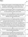
- FIG. 5 is a schematic flow diagram illustrating a method 500 of operating the power converter 104 according to an example.
- the power converter may be electrically coupled to a power grid and may output to the power grid converted electrical power.
- the power converter may be operable in a first operating mode in which the converter is operated based on a first reference generated by a virtual synchronous machine control and the power converter may further be operable in a second operating mode in which the converter is operated based on a second reference that is not generated by the virtual synchronous machine control scheme.
- the method 500 may comprise operating the power converter in the second operating mode.
- the method 500 may comprise obtaining a command/request to switch to the first operating mode.
- the method 500 may comprise switching the operation of the converter from the second operating mode into the first operating mode, wherein switching the operation may comprise steps S10, S15, S20 and S25.
- the method 500 may comprise obtaining one or more operating parameters indicative of grid voltage and/or of a current provided by the converter to the grid while operating in the second operating mode.
- the method 500 may comprise estimating from the one or more operating parameters a parameterization for the virtual synchronous machine control scheme, wherein the estimating includes calculating one or more values of the parameterization that will result in at least part of the obtained one or more operating parameters when the converter is operated in this first operating mode with this first reference generated by the virtual synchronous machine control scheme.
- Calculating one or more values of the parameterization may comprise calculating backwards from the obtained one or more operating parameters to the parametrization.
- the method 500 may comprise parameterizing the virtual synchronous machine control scheme with the estimated parameterization.
- the method 500 may comprise switching to the first operating mode by operating the virtual synchronous machine control scheme with the parametrization to generate the first reference and operating the converter based on the generated first reference.
Landscapes
- Engineering & Computer Science (AREA)
- Power Engineering (AREA)
- Control Of Eletrric Generators (AREA)
Priority Applications (4)
| Application Number | Priority Date | Filing Date | Title |
|---|---|---|---|
| EP22383013.4A EP4358342A1 (fr) | 2022-10-21 | 2022-10-21 | Fonctionnement d'un convertisseur de puissance |
| PCT/EP2023/079023 WO2024083929A1 (fr) | 2022-10-21 | 2023-10-18 | Fonctionnement d'un convertisseur de puissance |
| EP23790350.5A EP4584861A1 (fr) | 2022-10-21 | 2023-10-18 | Fonctionnement d'un convertisseur de puissance |
| CN202380074300.1A CN120077540A (zh) | 2022-10-21 | 2023-10-18 | 操作功率转换器 |
Applications Claiming Priority (1)
| Application Number | Priority Date | Filing Date | Title |
|---|---|---|---|
| EP22383013.4A EP4358342A1 (fr) | 2022-10-21 | 2022-10-21 | Fonctionnement d'un convertisseur de puissance |
Publications (1)
| Publication Number | Publication Date |
|---|---|
| EP4358342A1 true EP4358342A1 (fr) | 2024-04-24 |
Family
ID=84331960
Family Applications (2)
| Application Number | Title | Priority Date | Filing Date |
|---|---|---|---|
| EP22383013.4A Withdrawn EP4358342A1 (fr) | 2022-10-21 | 2022-10-21 | Fonctionnement d'un convertisseur de puissance |
| EP23790350.5A Pending EP4584861A1 (fr) | 2022-10-21 | 2023-10-18 | Fonctionnement d'un convertisseur de puissance |
Family Applications After (1)
| Application Number | Title | Priority Date | Filing Date |
|---|---|---|---|
| EP23790350.5A Pending EP4584861A1 (fr) | 2022-10-21 | 2023-10-18 | Fonctionnement d'un convertisseur de puissance |
Country Status (3)
| Country | Link |
|---|---|
| EP (2) | EP4358342A1 (fr) |
| CN (1) | CN120077540A (fr) |
| WO (1) | WO2024083929A1 (fr) |
Citations (3)
| Publication number | Priority date | Publication date | Assignee | Title |
|---|---|---|---|---|
| WO2021008664A1 (fr) * | 2019-07-15 | 2021-01-21 | Vestas Wind Systems A/S | Unité de production d'énergie à générateur synchrone virtuel à limitation de courant |
| EP3832829A1 (fr) * | 2019-12-02 | 2021-06-09 | ABB Schweiz AG | Commande de courant de vecteur de formation de grille |
| EP3968484A1 (fr) * | 2020-09-09 | 2022-03-16 | ABB Schweiz AG | Commande pour convertisseurs électriques |
-
2022
- 2022-10-21 EP EP22383013.4A patent/EP4358342A1/fr not_active Withdrawn
-
2023
- 2023-10-18 EP EP23790350.5A patent/EP4584861A1/fr active Pending
- 2023-10-18 CN CN202380074300.1A patent/CN120077540A/zh active Pending
- 2023-10-18 WO PCT/EP2023/079023 patent/WO2024083929A1/fr not_active Ceased
Patent Citations (3)
| Publication number | Priority date | Publication date | Assignee | Title |
|---|---|---|---|---|
| WO2021008664A1 (fr) * | 2019-07-15 | 2021-01-21 | Vestas Wind Systems A/S | Unité de production d'énergie à générateur synchrone virtuel à limitation de courant |
| EP3832829A1 (fr) * | 2019-12-02 | 2021-06-09 | ABB Schweiz AG | Commande de courant de vecteur de formation de grille |
| EP3968484A1 (fr) * | 2020-09-09 | 2022-03-16 | ABB Schweiz AG | Commande pour convertisseurs électriques |
Non-Patent Citations (3)
| Title |
|---|
| D'ARCO SALVATORE ET AL: "A synchronization controller for grid reconnection of islanded virtual synchronous machines", 2015 IEEE 6TH INTERNATIONAL SYMPOSIUM ON POWER ELECTRONICS FOR DISTRIBUTED GENERATION SYSTEMS (PEDG), IEEE, 22 June 2015 (2015-06-22), pages 1 - 8, XP033210015, DOI: 10.1109/PEDG.2015.7223046 * |
| D'ARCO SALVATORE ET AL: "Virtual synchronous machines - Classification of implementations and analysis of equivalence to droop controllers for microg", 2013 IEEE GRENOBLE CONFERENCE, IEEE, 16 June 2013 (2013-06-16), pages 1 - 7, XP032519741, DOI: 10.1109/PTC.2013.6652456 * |
| TAUL MADS GRAUNGAARD ET AL: "Current Limiting Control With Enhanced Dynamics of Grid-Forming Converters During Fault Conditions", IEEE JOURNAL OF EMERGING AND SELECTED TOPICS IN POWER ELECTRONICS, IEEE, PISCATAWAY, NJ, USA, vol. 8, no. 2, 27 July 2019 (2019-07-27), pages 1062 - 1073, XP011785931, ISSN: 2168-6777, [retrieved on 20200430], DOI: 10.1109/JESTPE.2019.2931477 * |
Also Published As
| Publication number | Publication date |
|---|---|
| CN120077540A (zh) | 2025-05-30 |
| WO2024083929A1 (fr) | 2024-04-25 |
| EP4584861A1 (fr) | 2025-07-16 |
Similar Documents
| Publication | Publication Date | Title |
|---|---|---|
| US11658478B2 (en) | Grid connected inverter, and method for reducing grid frequency variation | |
| Pradhan et al. | A composite sliding mode controller for wind power extraction in remotely located solar PV–wind hybrid system | |
| EP3376627B1 (fr) | Procédé et système de commande d'un convertisseur de puissance | |
| EP2963759B1 (fr) | Dispositif convertisseur de courant pour connexion au réseau | |
| CN118920514A (zh) | 一种逆变器控制方法、装置、计算机设备及存储介质 | |
| EP2773037A1 (fr) | Système de commande de système hydroélectrique de stockage pompé à vitesse variable et son procédé de commande | |
| CN112952898A (zh) | 变流器的控制模块、控制单元和其控制方法以及风能设备 | |
| Hamane et al. | Direct active and reactive power control of DFIG based WECS using PI and sliding mode controllers | |
| JP4775181B2 (ja) | 単独運転検出装置およびその単独運転検出方法、単独運転検出装置を内蔵したパワーコンディショナー | |
| JP7226560B2 (ja) | 再生可能エネルギー発電プラントシステムおよびプラント制御装置 | |
| WO2024083929A1 (fr) | Fonctionnement d'un convertisseur de puissance | |
| Korai et al. | New control approach for blackstart capability of full converter wind turbines with direct voltage control | |
| Cheng et al. | Fault tolerant control for power side current sensor in wind energy conversion system with cascaded brushless DFIG | |
| Nazib et al. | Dynamic grid frequency support using a self-synchronising grid-following inverter | |
| CN117856357A (zh) | 虚拟同步发电机暂态功角稳定增强控制方法及系统 | |
| Sobhy et al. | Enhancing the performance of the output active power of DFIG-based wind turbines using auto disturbance rejection control | |
| CN113497454B (zh) | Mmc-hvdc的内环电流控制器故障穿越控制方法 | |
| Diab et al. | Modified adaptive sliding mode control for sensorless direct-drive permanent magnet synchronous generator wind turbines based on fuzzy logic control | |
| Yadav et al. | Wind-Solar PV-BES Based Multifunctional Microgrid with Seamless Mode of Switching | |
| Dimple et al. | Direct Power Control of Grid Connected Double-Fed Induction Generator in Wind Energy Conversion System | |
| Lan et al. | A novel stator current observer for fault tolerant control of stator current sensor in DFIG | |
| Ouyessaad et al. | Fault sensor diagnosis with Takagi-Sugeno approach design applied for DFIG wind energy systems | |
| Ali et al. | A multi-machine power system stabilizer using fuzzy logic controller | |
| Neto et al. | Reduced order model for grid connected wind turbines with doubly fed induction generators | |
| JP2015171293A (ja) | 制御装置及び制御方法 |
Legal Events
| Date | Code | Title | Description |
|---|---|---|---|
| PUAI | Public reference made under article 153(3) epc to a published international application that has entered the european phase |
Free format text: ORIGINAL CODE: 0009012 |
|
| STAA | Information on the status of an ep patent application or granted ep patent |
Free format text: STATUS: THE APPLICATION HAS BEEN PUBLISHED |
|
| AK | Designated contracting states |
Kind code of ref document: A1 Designated state(s): AL AT BE BG CH CY CZ DE DK EE ES FI FR GB GR HR HU IE IS IT LI LT LU LV MC ME MK MT NL NO PL PT RO RS SE SI SK SM TR |
|
| STAA | Information on the status of an ep patent application or granted ep patent |
Free format text: STATUS: THE APPLICATION IS DEEMED TO BE WITHDRAWN |
|
| 18D | Application deemed to be withdrawn |
Effective date: 20241025 |