EP4358794B1 - Supporting device for furniture - Google Patents
Supporting device for furniture Download PDFInfo
- Publication number
- EP4358794B1 EP4358794B1 EP22744299.3A EP22744299A EP4358794B1 EP 4358794 B1 EP4358794 B1 EP 4358794B1 EP 22744299 A EP22744299 A EP 22744299A EP 4358794 B1 EP4358794 B1 EP 4358794B1
- Authority
- EP
- European Patent Office
- Prior art keywords
- supporting device
- plane
- furniture
- teeth
- reference teeth
- Prior art date
- Legal status (The legal status is an assumption and is not a legal conclusion. Google has not performed a legal analysis and makes no representation as to the accuracy of the status listed.)
- Active
Links
Images


Classifications
-
- A—HUMAN NECESSITIES
- A47—FURNITURE; DOMESTIC ARTICLES OR APPLIANCES; COFFEE MILLS; SPICE MILLS; SUCTION CLEANERS IN GENERAL
- A47B—TABLES; DESKS; OFFICE FURNITURE; CABINETS; DRAWERS; GENERAL DETAILS OF FURNITURE
- A47B91/00—Feet for furniture in general
- A47B91/02—Adjustable feet
- A47B91/022—Adjustable feet using screw means
- A47B91/024—Foot attached to a rotating bolt supported in an internal thread
Definitions
- the present invention relates to a supporting device for furniture, such as in particular a support foot adapted to be associated with a panel forming the side of the piece of furniture to adjust the vertical position thereof with respect to an essentially horizontal support surface, such as the floor.
- Support feet adapted to adjust the vertical position of a piece of furniture arranged on a support surface with the aim of compensating possible unevenness of the latter are well known on the market.
- they generally comprise two members, inserted one into the other, which - due to an adjustment mechanism - which can be actuated using an appropriate operating tool, can slide axially with respect to each other; the mutual movement between these two members allows to adjust the piece of furniture height-wise.
- one of said members is integrally joined to the support surface, while the other is adapted to be engaged with a part of the piece of furniture, generally a side and/or a bottom panel, to which it is constrained through appropriate fixing means.
- Constraining a supporting device of the type described above to the side of a piece of furniture usually requires approaching the device to the internal surface of the side, in proximity of the lower edge, then reaching the desired mounting position possibly by using reference means.
- the reference means are formed by pins protruding from the supporting device and adapted to be inserted into appropriate housing seats provided on the side of the piece of furniture.
- such solution envisages previously providing said housing seats on the panel, an operation which further requires particular precision.
- references means are formed by reference teeth, protruding from one or more support flanges adapted to be inserted beneath the side to improve the capacity thereof, are known.
- the known reference teeth lie on a plane essentially vertical and parallel to the internal surface of the side and they are configured to be pressure-fitted into the thickness of the panel, by introducing them at the lower head edge thereof.
- An example of a supporting device of this type is disclosed in KR870001861 Y1 .
- the main task of the present invention is to overcome the drawbacks of the prior art, providing a supporting device for furniture which can be pre-mounted on the panel forming the side of the piece of furniture before possibly stably fixing, but without damaging it and without requiring additional operations on the panel.
- an object of the present invention is to obtain a supporting device for furniture that is robust and functional, further allowing to adjust the vertical position of the furniture in a simple and immediate manner.
- Another object of the present invention is to provide an adjustable supporting device for pieces of furniture that is simple and cost-effective to produce, using the usual known machines and processes.
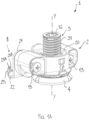
- said supporting device 1 is of the adjustable type, that is it allows to adjust the position of the side F, and therefore of the piece of furniture, along an adjusting axis Y-Y substantially perpendicular with respect to said support surface.
- said device 1 comprises a mounting element 2 which can be constrained to an internal surface F1 of the side F of the piece of furniture, preferably in proximity of a lower edge thereof in use adjacent to the floor, using fixing means 13.
- Said mounting element 2 is provided with a central body 20 defining a through seat that is internally threaded and extending along said adjusting axis Y-Y, essentially vertical in use, adapted to be engaged by an adjusting means 3 provided with a threaded rod 31 which rests with an end on said support surface and it is adapted to be axially rotatably operated to adjust the position of said side F with respect to the support surface.
- said adjusting means 3 has, at the first end of said threaded rod 31, substantially facing - in use - toward the support surface, a support base 4 configured so as to expand the surface area of the supporting device 1 on the support surface as much as possible and therefore optimally discharge the weight of the piece of furniture.
- said supporting device 1 further comprises reference means 8 having the purpose of allowing pre-mounting to the side F of the mounting element 2, holding it in position with the correct orientation before possibly stably fixing it by using said fixing screws 13.
- said reference means 8 comprise at least one pair of reference teeth 23 adapted to be pressure-fitted into the thickness of said side F, introducing them from a lower head edge F2 thereof, said reference teeth 23 lying each on an essentially vertical respective plane P3, inclined with respect to said first plane P1 and therefore, in use, with respect to the internal surface F1 of said side F.
- said reference means 8 further comprise a support flange 22, essentially formed by at least one flat plate protruding from the lower edge of said central body 20, and preferably from the lower edge of said coupling portion 21, so as to lie on a second plane P2, essentially horizontal in use, as shown in figure 2 .
- said support flange 22 may be formed by a pair of flat plates, each preferably protruding from the lower edge of a respective coupling portion 21.
- Said support flange 22 is adapted to be inserted beneath the panel forming the side F of the piece of furniture, and cooperate abutting against the lower head edge F2 thereof to create a reference for mounting the mounting element 2 and advantageously improve the capacity of the device 1.
- said reference teeth 23 protrude vertically from the upper surface of said support flange 22, lying on a plane essentially orthogonal to the second plane P2, and they are arranged preferably at a free end edge thereof.
- Said support flange 22 preferably has an extension smaller than the thickness of the side F and it is configured so that said reference teeth 23 fit into an essentially central area of the thickness of the side F, that is at an intermediate distance between the inner surface F1 and the outer surface F2 of the latter.
- said reference teeth 23 are preferably arranged in an essentially mirror-like fashion with respect to a symmetry plane X substantially orthogonal to said first plane P1, vertical in use, and oriented in a manner such to converge towards the outer surface F3 of the side F.
- said reference teeth 23 are pressure-fitted into the thickness of the side F, penetrating from the lower head edge F2 thereof, they are oriented along inclined planes with respect to the internal F1 and external F3 surfaces thereof, therefore preventing them from diverging, in particular when the piece of furniture is loaded and therefore limiting the risk of breaking the panel.
- such solution advantageously moves the main line of the force generated by the reference teeth 23 when they enter into the side F: advantageously, the main line is oriented in a direction orthogonal to said teeth 23, thus affecting not only the thickness of the side F but also partly the depth thereof.
- said reference teeth 23 preferably have a shape essentially tapered towards the free end 23A so as to facilitate the insertion thereof into the thickness of the side F and they have a protruding portion 23B, also advantageously tapered towards the free end 23A, preferably obtained on the surface of each tooth 23 facing towards the respective coupling portion 21, adapted to prevent it from coming out once introduced into the side F, therefore ensuring that the device 1 is held in the correct position by interference and preventing said support flange 22 from being inadvertently detached from the lower edge F2 of the side F, for example during the subsequent step of fixing the device 1 using said fixing screws 13.
- said coupling portions 21 are initially approached to the internal surface F1, at the lower edge thereof, positioning said support flange 22 in proximity of the lower head edge F2.
- said reference teeth 23 are pressure-fitted into the thickness of the side F, introducing them from the lower head edge F2, until said support flange 22 essentially abuts thereagainst.
- said reference teeth 23 are essentially fully received in the thickness of the panel forming the side F, inclined with respect to the internal F1 and external F3 surfaces of the latter, and the protruding portions 23B prevent the removal thereof by interference.
- the device 1 is therefore advantageously pre-mounted in the correct position to the side F of the piece of furniture and it may be stably constrained to the side F by inserting the fixing screws 13 into the corresponding fixing holes 21A provided for on said coupling portions 21, until they are fully screwed into the panel.
- a horizontal panel B forming the bottom of the piece of furniture, preferably provided with a through hole suitably obtained in the thickness of the latter to allow access - using a tool - to the adjusting means 3 of the supporting device 1 so as to be able to carry out the desired adjustments, may be arranged above it.
- a supporting device for furniture according to the invention is also robust and functional, and it allows to be able to adjust the vertical position of the piece of furniture in a simple and immediate manner.
Landscapes
- Legs For Furniture In General (AREA)
- Furniture Connections (AREA)
- Supports Or Holders For Household Use (AREA)
Applications Claiming Priority (2)
| Application Number | Priority Date | Filing Date | Title |
|---|---|---|---|
| IT202021000003344U IT202100003344U1 (it) | 2021-06-25 | 2021-06-25 | “dispositivo di supporto perfezionato per mobili” |
| PCT/IB2022/055370 WO2022269400A1 (en) | 2021-06-25 | 2022-06-09 | Improved supporting device for furniture |
Publications (2)
| Publication Number | Publication Date |
|---|---|
| EP4358794A1 EP4358794A1 (en) | 2024-05-01 |
| EP4358794B1 true EP4358794B1 (en) | 2025-04-30 |
Family
ID=82611092
Family Applications (1)
| Application Number | Title | Priority Date | Filing Date |
|---|---|---|---|
| EP22744299.3A Active EP4358794B1 (en) | 2021-06-25 | 2022-06-09 | Supporting device for furniture |
Country Status (6)
| Country | Link |
|---|---|
| EP (1) | EP4358794B1 (pl) |
| CN (1) | CN117241703A (pl) |
| ES (1) | ES3030921T3 (pl) |
| IT (1) | IT202100003344U1 (pl) |
| PL (1) | PL4358794T3 (pl) |
| WO (1) | WO2022269400A1 (pl) |
Families Citing this family (1)
| Publication number | Priority date | Publication date | Assignee | Title |
|---|---|---|---|---|
| GB2643919A (en) * | 2024-09-06 | 2026-03-11 | Devol Kitchens Ltd | Cabinet Foot |
Family Cites Families (4)
| Publication number | Priority date | Publication date | Assignee | Title |
|---|---|---|---|---|
| US3722565A (en) * | 1971-08-02 | 1973-03-27 | Miller R & Co Inc | Barbed t-nut |
| KR870001861Y1 (ko) * | 1983-03-19 | 1987-05-21 | 박운하 | 가구의 높이 조절구 |
| CN108244845B (zh) * | 2018-01-20 | 2021-04-02 | 厦门顾信家居有限公司 | 一种平衡衣柜及其制作工艺 |
| CN210976442U (zh) * | 2019-09-10 | 2020-07-10 | 匡世实业有限公司 | 扣件 |
-
2021
- 2021-06-25 IT IT202021000003344U patent/IT202100003344U1/it unknown
-
2022
- 2022-06-09 ES ES22744299T patent/ES3030921T3/es active Active
- 2022-06-09 EP EP22744299.3A patent/EP4358794B1/en active Active
- 2022-06-09 WO PCT/IB2022/055370 patent/WO2022269400A1/en not_active Ceased
- 2022-06-09 PL PL22744299.3T patent/PL4358794T3/pl unknown
- 2022-06-09 CN CN202280032690.1A patent/CN117241703A/zh active Pending
Also Published As
| Publication number | Publication date |
|---|---|
| ES3030921T3 (en) | 2025-07-02 |
| CN117241703A (zh) | 2023-12-15 |
| WO2022269400A1 (en) | 2022-12-29 |
| IT202100003344U1 (it) | 2022-12-25 |
| PL4358794T3 (pl) | 2025-08-11 |
| EP4358794A1 (en) | 2024-05-01 |
Similar Documents
| Publication | Publication Date | Title |
|---|---|---|
| AU682775B2 (en) | Fastening device for a tool or work piece | |
| JP6763650B2 (ja) | 高さ調整装置を備えた昇降テーブル | |
| US5603142A (en) | Frame hinge | |
| KR20160005689A (ko) | 캐비닛 상에 도어를 재치하기 위한 조절 가능한 힌지 | |
| EP4358794B1 (en) | Supporting device for furniture | |
| JPS5830085B2 (ja) | 互換性をもつ多角形植刃付工具 | |
| US11913206B1 (en) | Sink mounting apparatus | |
| EP4069037B1 (en) | Angular support device adapted to support a wall cabinet on a wall | |
| JP2009095422A (ja) | テーブル用脚の取付具およびテーブル | |
| EP0469668B1 (en) | Leg attaching tool | |
| US6164114A (en) | Compensation device for a press brake | |
| US4830529A (en) | Device for fixing an object against a supporting surface | |
| KR101610798B1 (ko) | 테이블용 다리의 부착구 및 테이블 | |
| CA2542801A1 (en) | Connecting device for fixing flat-shaped seperation elements | |
| KR100417021B1 (ko) | 건축물 외벽 치장용 석재 고정장치 | |
| KR20130128721A (ko) | 건축외장재 설치용 고정구 | |
| IT202300008829A1 (it) | Dispositivo di supporto regolabile a scomparsa di mensole a sbalzo | |
| JP7770172B2 (ja) | 不陸調整構造 | |
| KR20190017592A (ko) | 건축용 석재패널 장착용 앵글부재 | |
| JP6534346B2 (ja) | 浴室部材の締結構造 | |
| KR20080048748A (ko) | 무빙 지그 | |
| US8955288B1 (en) | Low profile adjustable lift bracket | |
| CN220725638U (zh) | 一种架空地板结构 | |
| JP7366508B2 (ja) | キャビネット | |
| KR200234581Y1 (ko) | 건축물 외벽 치장용 석재 고정장치 |
Legal Events
| Date | Code | Title | Description |
|---|---|---|---|
| STAA | Information on the status of an ep patent application or granted ep patent |
Free format text: STATUS: UNKNOWN |
|
| STAA | Information on the status of an ep patent application or granted ep patent |
Free format text: STATUS: THE INTERNATIONAL PUBLICATION HAS BEEN MADE |
|
| PUAI | Public reference made under article 153(3) epc to a published international application that has entered the european phase |
Free format text: ORIGINAL CODE: 0009012 |
|
| STAA | Information on the status of an ep patent application or granted ep patent |
Free format text: STATUS: REQUEST FOR EXAMINATION WAS MADE |
|
| 17P | Request for examination filed |
Effective date: 20231122 |
|
| AK | Designated contracting states |
Kind code of ref document: A1 Designated state(s): AL AT BE BG CH CY CZ DE DK EE ES FI FR GB GR HR HU IE IS IT LI LT LU LV MC MK MT NL NO PL PT RO RS SE SI SK SM TR |
|
| P01 | Opt-out of the competence of the unified patent court (upc) registered |
Free format text: CASE NUMBER: APP_35477/2024 Effective date: 20240613 |
|
| DAV | Request for validation of the european patent (deleted) | ||
| DAX | Request for extension of the european patent (deleted) | ||
| GRAP | Despatch of communication of intention to grant a patent |
Free format text: ORIGINAL CODE: EPIDOSNIGR1 |
|
| STAA | Information on the status of an ep patent application or granted ep patent |
Free format text: STATUS: GRANT OF PATENT IS INTENDED |
|
| INTG | Intention to grant announced |
Effective date: 20250130 |
|
| GRAS | Grant fee paid |
Free format text: ORIGINAL CODE: EPIDOSNIGR3 |
|
| GRAA | (expected) grant |
Free format text: ORIGINAL CODE: 0009210 |
|
| STAA | Information on the status of an ep patent application or granted ep patent |
Free format text: STATUS: THE PATENT HAS BEEN GRANTED |
|
| AK | Designated contracting states |
Kind code of ref document: B1 Designated state(s): AL AT BE BG CH CY CZ DE DK EE ES FI FR GB GR HR HU IE IS IT LI LT LU LV MC MK MT NL NO PL PT RO RS SE SI SK SM TR |
|
| REG | Reference to a national code |
Ref country code: CH Ref legal event code: EP Ref country code: GB Ref legal event code: FG4D |
|
| REG | Reference to a national code |
Ref country code: DE Ref legal event code: R096 Ref document number: 602022013964 Country of ref document: DE |
|
| REG | Reference to a national code |
Ref country code: IE Ref legal event code: FG4D |
|
| REG | Reference to a national code |
Ref country code: NL Ref legal event code: FP |
|
| REG | Reference to a national code |
Ref country code: ES Ref legal event code: FG2A Ref document number: 3030921 Country of ref document: ES Kind code of ref document: T3 Effective date: 20250702 |
|
| PGFP | Annual fee paid to national office [announced via postgrant information from national office to epo] |
Ref country code: DE Payment date: 20250618 Year of fee payment: 4 |
|
| PGFP | Annual fee paid to national office [announced via postgrant information from national office to epo] |
Ref country code: NL Payment date: 20250618 Year of fee payment: 4 |
|
| PGFP | Annual fee paid to national office [announced via postgrant information from national office to epo] |
Ref country code: AT Payment date: 20250721 Year of fee payment: 4 |
|
| PG25 | Lapsed in a contracting state [announced via postgrant information from national office to epo] |
Ref country code: PT Free format text: LAPSE BECAUSE OF FAILURE TO SUBMIT A TRANSLATION OF THE DESCRIPTION OR TO PAY THE FEE WITHIN THE PRESCRIBED TIME-LIMIT Effective date: 20250901 Ref country code: FI Free format text: LAPSE BECAUSE OF FAILURE TO SUBMIT A TRANSLATION OF THE DESCRIPTION OR TO PAY THE FEE WITHIN THE PRESCRIBED TIME-LIMIT Effective date: 20250430 |
|
| PGFP | Annual fee paid to national office [announced via postgrant information from national office to epo] |
Ref country code: ES Payment date: 20250731 Year of fee payment: 4 |
|
| REG | Reference to a national code |
Ref country code: LT Ref legal event code: MG9D |
|
| PG25 | Lapsed in a contracting state [announced via postgrant information from national office to epo] |
Ref country code: GR Free format text: LAPSE BECAUSE OF FAILURE TO SUBMIT A TRANSLATION OF THE DESCRIPTION OR TO PAY THE FEE WITHIN THE PRESCRIBED TIME-LIMIT Effective date: 20250731 Ref country code: NO Free format text: LAPSE BECAUSE OF FAILURE TO SUBMIT A TRANSLATION OF THE DESCRIPTION OR TO PAY THE FEE WITHIN THE PRESCRIBED TIME-LIMIT Effective date: 20250730 |
|
| PGFP | Annual fee paid to national office [announced via postgrant information from national office to epo] |
Ref country code: PL Payment date: 20250522 Year of fee payment: 4 Ref country code: IT Payment date: 20250630 Year of fee payment: 4 |
|
| PG25 | Lapsed in a contracting state [announced via postgrant information from national office to epo] |
Ref country code: BG Free format text: LAPSE BECAUSE OF FAILURE TO SUBMIT A TRANSLATION OF THE DESCRIPTION OR TO PAY THE FEE WITHIN THE PRESCRIBED TIME-LIMIT Effective date: 20250430 |
|
| PG25 | Lapsed in a contracting state [announced via postgrant information from national office to epo] |
Ref country code: HR Free format text: LAPSE BECAUSE OF FAILURE TO SUBMIT A TRANSLATION OF THE DESCRIPTION OR TO PAY THE FEE WITHIN THE PRESCRIBED TIME-LIMIT Effective date: 20250430 |
|
| PG25 | Lapsed in a contracting state [announced via postgrant information from national office to epo] |
Ref country code: RS Free format text: LAPSE BECAUSE OF FAILURE TO SUBMIT A TRANSLATION OF THE DESCRIPTION OR TO PAY THE FEE WITHIN THE PRESCRIBED TIME-LIMIT Effective date: 20250731 |
|
| PG25 | Lapsed in a contracting state [announced via postgrant information from national office to epo] |
Ref country code: IS Free format text: LAPSE BECAUSE OF FAILURE TO SUBMIT A TRANSLATION OF THE DESCRIPTION OR TO PAY THE FEE WITHIN THE PRESCRIBED TIME-LIMIT Effective date: 20250830 |
|
| PG25 | Lapsed in a contracting state [announced via postgrant information from national office to epo] |
Ref country code: LV Free format text: LAPSE BECAUSE OF FAILURE TO SUBMIT A TRANSLATION OF THE DESCRIPTION OR TO PAY THE FEE WITHIN THE PRESCRIBED TIME-LIMIT Effective date: 20250430 |
|
| PG25 | Lapsed in a contracting state [announced via postgrant information from national office to epo] |
Ref country code: DK Free format text: LAPSE BECAUSE OF FAILURE TO SUBMIT A TRANSLATION OF THE DESCRIPTION OR TO PAY THE FEE WITHIN THE PRESCRIBED TIME-LIMIT Effective date: 20250430 Ref country code: SM Free format text: LAPSE BECAUSE OF FAILURE TO SUBMIT A TRANSLATION OF THE DESCRIPTION OR TO PAY THE FEE WITHIN THE PRESCRIBED TIME-LIMIT Effective date: 20250430 |
|
| PG25 | Lapsed in a contracting state [announced via postgrant information from national office to epo] |
Ref country code: CZ Free format text: LAPSE BECAUSE OF FAILURE TO SUBMIT A TRANSLATION OF THE DESCRIPTION OR TO PAY THE FEE WITHIN THE PRESCRIBED TIME-LIMIT Effective date: 20250430 |
|
| PG25 | Lapsed in a contracting state [announced via postgrant information from national office to epo] |
Ref country code: EE Free format text: LAPSE BECAUSE OF FAILURE TO SUBMIT A TRANSLATION OF THE DESCRIPTION OR TO PAY THE FEE WITHIN THE PRESCRIBED TIME-LIMIT Effective date: 20250430 |
|
| PG25 | Lapsed in a contracting state [announced via postgrant information from national office to epo] |
Ref country code: SK Free format text: LAPSE BECAUSE OF FAILURE TO SUBMIT A TRANSLATION OF THE DESCRIPTION OR TO PAY THE FEE WITHIN THE PRESCRIBED TIME-LIMIT Effective date: 20250430 |
|
| REG | Reference to a national code |
Ref country code: CH Ref legal event code: H13 Free format text: ST27 STATUS EVENT CODE: U-0-0-H10-H13 (AS PROVIDED BY THE NATIONAL OFFICE) Effective date: 20260127 |
|
| PG25 | Lapsed in a contracting state [announced via postgrant information from national office to epo] |
Ref country code: MC Free format text: LAPSE BECAUSE OF FAILURE TO SUBMIT A TRANSLATION OF THE DESCRIPTION OR TO PAY THE FEE WITHIN THE PRESCRIBED TIME-LIMIT Effective date: 20250430 |
|
| REG | Reference to a national code |
Ref country code: DE Ref legal event code: R097 Ref document number: 602022013964 Country of ref document: DE |
|
| PG25 | Lapsed in a contracting state [announced via postgrant information from national office to epo] |
Ref country code: LU Free format text: LAPSE BECAUSE OF NON-PAYMENT OF DUE FEES Effective date: 20250609 |
|
| REG | Reference to a national code |
Ref country code: BE Ref legal event code: MM Effective date: 20250630 |
|
| PG25 | Lapsed in a contracting state [announced via postgrant information from national office to epo] |
Ref country code: RO Free format text: LAPSE BECAUSE OF FAILURE TO SUBMIT A TRANSLATION OF THE DESCRIPTION OR TO PAY THE FEE WITHIN THE PRESCRIBED TIME-LIMIT Effective date: 20250430 |
|
| PLBE | No opposition filed within time limit |
Free format text: ORIGINAL CODE: 0009261 |
|
| STAA | Information on the status of an ep patent application or granted ep patent |
Free format text: STATUS: NO OPPOSITION FILED WITHIN TIME LIMIT |
|
| REG | Reference to a national code |
Ref country code: CH Ref legal event code: L10 Free format text: ST27 STATUS EVENT CODE: U-0-0-L10-L00 (AS PROVIDED BY THE NATIONAL OFFICE) Effective date: 20260311 |
|
| 26N | No opposition filed |
Effective date: 20260202 |
|
| PG25 | Lapsed in a contracting state [announced via postgrant information from national office to epo] |
Ref country code: IE Free format text: LAPSE BECAUSE OF NON-PAYMENT OF DUE FEES Effective date: 20250609 |
|
| PG25 | Lapsed in a contracting state [announced via postgrant information from national office to epo] |
Ref country code: BE Free format text: LAPSE BECAUSE OF NON-PAYMENT OF DUE FEES Effective date: 20250630 |
|
| PG25 | Lapsed in a contracting state [announced via postgrant information from national office to epo] |
Ref country code: FR Free format text: LAPSE BECAUSE OF NON-PAYMENT OF DUE FEES Effective date: 20250630 |