EP4359639B1 - Outil de puits de fond de trou et procédé pour sceller de manière permanente d'un puits de fond de trou - Google Patents
Outil de puits de fond de trou et procédé pour sceller de manière permanente d'un puits de fond de trou Download PDFInfo
- Publication number
- EP4359639B1 EP4359639B1 EP22731637.9A EP22731637A EP4359639B1 EP 4359639 B1 EP4359639 B1 EP 4359639B1 EP 22731637 A EP22731637 A EP 22731637A EP 4359639 B1 EP4359639 B1 EP 4359639B1
- Authority
- EP
- European Patent Office
- Prior art keywords
- compartment
- downhole well
- well tool
- sealing element
- expandable sealing
- Prior art date
- Legal status (The legal status is an assumption and is not a legal conclusion. Google has not performed a legal analysis and makes no representation as to the accuracy of the status listed.)
- Active
Links
Images






Classifications
-
- E—FIXED CONSTRUCTIONS
- E21—EARTH OR ROCK DRILLING; MINING
- E21B—EARTH OR ROCK DRILLING; OBTAINING OIL, GAS, WATER, SOLUBLE OR MELTABLE MATERIALS OR A SLURRY OF MINERALS FROM WELLS
- E21B33/00—Sealing or packing boreholes or wells
- E21B33/10—Sealing or packing boreholes or wells in the borehole
- E21B33/12—Packers; Plugs
- E21B33/1204—Packers; Plugs permanent; drillable
-
- E—FIXED CONSTRUCTIONS
- E21—EARTH OR ROCK DRILLING; MINING
- E21B—EARTH OR ROCK DRILLING; OBTAINING OIL, GAS, WATER, SOLUBLE OR MELTABLE MATERIALS OR A SLURRY OF MINERALS FROM WELLS
- E21B17/00—Drilling rods or pipes; Flexible drill strings; Kellies; Drill collars; Sucker rods; Cables; Casings; Tubings
- E21B17/10—Wear protectors; Centralising devices, e.g. stabilisers
- E21B17/1078—Stabilisers or centralisers for casing, tubing or drill pipes
-
- E—FIXED CONSTRUCTIONS
- E21—EARTH OR ROCK DRILLING; MINING
- E21B—EARTH OR ROCK DRILLING; OBTAINING OIL, GAS, WATER, SOLUBLE OR MELTABLE MATERIALS OR A SLURRY OF MINERALS FROM WELLS
- E21B33/00—Sealing or packing boreholes or wells
- E21B33/10—Sealing or packing boreholes or wells in the borehole
- E21B33/12—Packers; Plugs
- E21B33/1208—Packers; Plugs characterised by the construction of the sealing or packing means
Definitions
- the present invention relates to a downhole well tool for permanently sealing a downhole well and a method for permanently sealing a downhole well.
- downhole plugs Different types are known. Their purpose is typically to seal off a downhole bore (for example a casing or a production tubing) during a well operation. Some downhole plugs are retrievable, i.e. after a period of time, a retrieving tool are used to retrieve the plug to topside again. Other downhole plugs are permanent plugs.
- plugs are often referred to as high expansion plugs.
- the expansion rate defined as the ratio between the outer diameter in the set state and the outer diameter in the run state, is relatively higher than for other groups of plugs.
- These plugs are designed to pass a relatively narrow restriction in the well and then expand to seal off the well bore below the narrow restriction.
- the sealing device comprises a sealing element and supporting devices on its upper and lower sides.
- Each supporting device comprises a number of first supporting arms and a number of second supporting arms having their first ends pivotably connected to a supporting ring provided around the mandrel and where their second ends are pivotably connected to each other.
- This principle is used in the commercially available High Expansion Retrievable Bridge plug (HEX plug), sold and marketed by Interwell.
- HEX plug High Expansion Retrievable Bridge plug
- One of the HEX plugs is made for use in a 7" 29 pounds/feet well pipe, where the specification for such pipes allows the inner diameter of the pipe to vary in a range between ca 154.6 - 159.8 mm, i.e. a variation in the distance between the outside of the supporting arms of the plug in its set state to the inner surface of the well pipe up to 3 mm.
- One object of the invention is to provide a tool which is insertable through a relatively narrow restriction in a well and which is radially expandable in a relatively wider section of the well below the narrow restriction.
- molten bismuth In plugging and abandonment (P&A) operations, permanent plugs are initially set in the well. Then, molten bismuth may be supplied above the permanent plug. Bismuth has expanding properties, i.e. the volume of the metal is larger when solidified than when molten. Hence, solidified bismuth serves as an additional barrier above the permanent plug. Typically, a relatively large amount of bismuth is required, which in turn require a relatively large heater in the well to melt the bismuth at the desired location in the well. According to the report "European Commission, Study on the EU's list of Critical Raw Materials - Final Report (2020)", bismuth is considered to be a critical raw material. Hence, one purpose of the present invention is to be able to reduce the amount of bismuth when providing a bismuth-type of barrier in a well.
- NO334913 describes a method and apparatus includes providing an element formed of a superplastic material to perform a predetermined downhole task.
- a method and apparatus includes a flowable element and a deformable element that can be expanded by flowing the flowable element.
- GB2420361A describes an apparatus, casing and method is disclosed for heating a material used for sealing faults within the cement used for sealing an oil or gas well.
- the apparatus comprises a heating tool, a hollow core within the tool for carrying meltable material and for allowing the material to liquefy upon heating by the heating tool, a piston within the heating tool for applying pressure to the material following the liquefying of the material within the tool and for forcing the liquefied material from the tool through perforations and into adjacent well cement 300 and formation.
- the casing may have a meltable material of a predetermined thickness over a predetermined length of the casing.
- WO2018/033760 describes a method of sealing a region of a sand screen of an Open Hole Gravel Pack without the need to perforate the sand screen and a tool for use in such.
- the tool being a eutectic/ bismuth based alloy well plugging/sealing tool having a tubular heater body with an internal cavity capable of receiving a chemical heat source.
- the tool is provided with a quantity of eutectic/bismuth based alloy around an outer surface of the heater body such that it can be heated by the chemical heat source.
- the tool has an insulating sleeve provided around an outer surface of the alloy, wherein the sleeve is configured to provide a focused egress for the alloy as it is melted by the chemical heat source.
- WO2019/151870 describes a method, system and plug for providing a cross-sectional seal in a well comprising a pipe body and an annulus, the method comprising: lowering a pipe expansion device into the pipe body to a selected location; with the pipe expansion device, expanding a section of the pipe body until contact with a wellbore wall, thus forming an expanded pipe section closing the annulus; lowering a fusible solid material into the expanded pipe section; lowering a heating tool into the expanded pipe section; activating the heating tool and melting the fusible solid material and allowing a molten mass thereof to fill a cross-sectional portion of the expanded pipe section; and deactivating the heating tool and allowing the molten mass to solidify and form the cross-sectional seal.
- CA3100822 describes a downhole tool deployment assembly for use in particular in oil/gas wells.
- the assembly comprises a heater with a tubular heater body having an internal cavity configured to receive a heat source.
- the assembly also has a tubular heat conducting member configured to surround the tubular heater body leaving an annular clearance, wherein the tubular heat conducting member does not extend along the entire length of the tubular heater body.
- a collar is mounted adjacent to the region of the assembly where the tubular heat conducting member ends. The collar is configured to prevent access to the annular clearance between the tubular heat conducting member and the tubular heater body.
- a eutectic/bismuth based alloy covers the collar and at least a portion of the tubular heater body and the tubular heat conducting member such that the alloy holds the heater and the tubular heat conducting member together until the alloy is melted.
- Another object of the present invention is to provide an alternative P&A barrier in the well.
- the present invention relates to a downhole well tool for permanently sealing a downhole well, wherein the downhole well tool comprises:
- the downhole well tool is a millable permanent downhole well tool, which is easy to remove by a milling operation, as no parts of the well tool can be rotated relative to other parts of the well tool.
- the millable permanent downhole well tool is a millable permanent plug.
- the downhole well tool is a high expansion well tool which typically is lowered in the run state through a restriction in the well, and thereafter expanded to its set state. If the restriction is not removed, a so-called under-reamer may be used to remove the set downhole well tool.
- the expandable sealing element comprises an elastomeric material reinforced with a fiber element structure.
- the fiber element structure may comprise several fibers.
- the fibers may be connected to each other.
- the fibers may be held relative to other fibers by means of the elastomeric material of the sealing element.
- the material of the elastomeric material and the fibre element structure is heat resistant with respect to the heat from the molten metal.
- the fibers may be aramid fibers, carbon fibers etc.
- the fiber element structure is determining the shape of the expandable sealing element in the intermediate state.
- the fiber element structure is flexible. In one aspect, the expandable sealing element with its fiber element structure is folded outside of the housing in the run state.
- the fibre element structure is applied with a sealing agent.
- the sealing agent is a polymer.
- the expandable sealing element comprises a cylindrical contact surface in the intermediate and set states.
- the cylindrical contact surface is brought into sealing contact with the inner surface of the well. Hence, the cylindrical contact surface is preventing longitudinal fluid flow in the annulus between the outside of the housing and the inside of the well.
- the cylindrical contact surface is further preventing longitudinal movement between the well tool and the well.
- the outer diameter of the cylindrical contact surface of the expandable sealing element in a free set state is 1.5 - 10% larger than the average inner diameter of the well.
- free set state is referring to a state in which the well tool is not restricted, for example by the well, when set.
- the well tool comprises a centralizer connected to the housing.
- the centralizer is radially expanded into contact with the well at the desired location before or in the intermediate state, to orient the expandable sealing element with respect to the well.
- the centralizer may also reduce the pressure needed for expanding the sealing element in the intermediate state.
- the centralizer comprises slips for anchoring of the well tool to the well. Hence, the centralizer is preventing longitudinal movement between the well tool and the well.
- the heater is an electric heater.
- the heater may be a chemical heater, for example a heater heated by means of a exothermic oxidation-reduction reaction, for example a thermite reaction.
- the heater is provided adjacent to or within the first compartment.
- the metal body comprises a metal or metal alloy whose volume is larger when solidified than when molten.
- the metal body comprises a metal having or metal alloy having a melting temperature lower than the melting temperature of the housing metal.
- the metal body comprises a bismuth or a bismuth alloy.
- a relatively small amount of bismuth-metal may be used.
- the upper housing section is releasably connected to the lower housing section by a releasable securing element.
- the securing element is a shear element, such as a shear pin.
- the lower housing section and the expandable sealing element filled with solidified metal may in the set state be considered as a downhole permanent plug, while the upper housing section may be considered as a setting tool for the downhole permanent plug.
- the setting tool or at least parts of the setting tool may be reused.
- the downhole well tool comprises a piston slidingly and sealingly engaged within the first compartment for displacing the molten metal from the first compartment to the second compartment in the intermediate state.
- the molten metal will flow from the first compartment to the second compartment due to gravity.
- the pressurized gas will move the piston, thereby causing the molten metal to flow into the second compartment via the fluid line.
- the expandable sealing element comprises a first end sleeve and a second end sleeve, wherein the cylindrical contact surface is located longitudinally between the first end sleeve and a second end sleeve.
- the expandable sealing element comprises a first intermediate section between the first end sleeve and cylindrical contact surface, wherein the first intermediate section is cone-shaped in the intermediate and set states.
- the expandable sealing element comprises a second intermediate section between the second end sleeve and cylindrical contact surface, wherein the second intermediate section is cone-shaped in the intermediate and set states.
- the setting system comprises:
- the spring will displace the second sleeve holder relative to the lower housing section towards the first sleeve holder, thereby causing or at least contributing to radial expansion of the expandable sealing element into contact with the well. This will make it easier for the molten metal to flow into the sealing element, either by gravity or by means of the piston.
- a distance between the first end sleeve and the second end sleeve is longer in the run state than in the set state.
- the releasable securing element is a meltable securing element
- the setting system comprises an auxiliary heater for melting the meltable locking element
- the housing comprises a spring support for supporting the spring.
- the spring is biased between the spring support and the second sleeve holder.
- the spring support is forming a lower end of the housing.
- the upper housing section and/or lower housing section comprises a wire channel for guiding an electric wire to the auxiliary heater and/or the heater.
- the setting system comprises a battery unit provided in the upper housing section for supplying electric power to the auxiliary heater and/or the heater.
- electric power may be transferred from topside via an e-line or other electric power supply line.
- the present invention also relates to a method for setting a downhole well tool as described above in a downhole well, wherein the method comprises the steps of:
- the downhole well tool comprises a piston slidingly and sealingly engaged within the first compartment for displacing the molten metal from the first compartment to the second compartment in the intermediate state and the the piston separates the first compartment into a first sub-compartment in which the metal body is provided and a second sub-compartment in which a pressurized gas is provided
- the step of supplying molten metal is comprising the steps of:
- the step of expanding the expandable sealing element further comprises the step of:
- the invention is set out in independent down hole well tool claim 1 and independent method claim 20.
- Optional and additional features are furthermore set out in the respective independent claims.
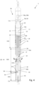
- a downhole well tool 1 is shown to comprise a housing 11 having an upper housing section 11a and an upper housing section 11b.
- the tool 1 comprises a expandable sealing element 20 provided circumferentially outside of the lower housing section 11b.
- the expandable sealing element 20 is radially retracted, and the tool 1 is in its radially retracted state or run state.
- the expandable sealing element 20 is radially expanded, and the tool 1 is in its radially expanded state or set state.
- the downhole well tool 1 may be considered to comprise two main parts: a first part in the form of a downhole permanent plug 10 for permanently sealing a downhole well WE (the well WE is indicated in fig. 9 ), and a second part in the form of a setting tool 100 which is retrieved topside after the setting operation of the downhole permanent plug 10. The setting tool 100 may then be used again to set another downhole permanent plug 10.
- FIG. 4 It is now referred to fig. 4 .
- the details of the housing 11 are shown more in detail, with its upper housing section 11a and its lower housing section 11b. It is here also shown better how the expandable sealing element 20 are provided circumferentially outside of the lower housing section 11b.
- a wireline interface 2 is shown in the upper end of the housing 11.
- a longitudinal direction of the housing is indicated as a dashed line I-I in fig. 4 .
- the tool 1 is defined with a first compartment 12 provided within housing 11 and a second compartment 14 radially inside of the expandable sealing element 20 and radially outside of the lower housing section 11b. It is further shown that the tool 1 comprises a fluid line 17 providing fluid communication between the first compartment 12 and the second compartment 14. The fluid line 17 is at least partially integrated within the housing 11.
- a piston 13 is slidingly and sealingly engaged within the first compartment 12.
- the piston 13 separates the first compartment 12 into a first sub-compartment 12a and a second sub-compartment 12b, wherein the second sub-compartment 12b is located below the first sub-compartment 12a.
- the second sub-compartment 12b is in fluid communication with the second compartment 14 via the fluid line 17.
- the upper housing section 11a is releasably connected to the lower housing section 11b by means of two releasable securing elements, a first, meltable securing element 58 and a shear element 18. These elements will be described further in detail below.
- the housing 11 further comprises a wire channel 19 for guiding one or more electric wires inside the housing 11.
- the lower end of the housing 11 further comprises a spring support 11c, which will also be described further in detail below.
- the expandable sealing element 20 is the expandable sealing element 20
- the shape of the expandable sealing element 20 will now be described when it is in its set state as shown in fig. 5 .
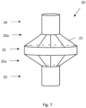
- the expandable sealing element 20 comprises an elastomeric material reinforced with a fiber element structure 21 ( fig. 7 ).
- the purpose of the fiber element structure 21 is to reinforce the elastomeric material.
- the purpose of the fiber element structure 21 is to contribute to maintain the desired shape of the expandable sealing element 20 in the expanded state.
- the expandable sealing element 20 is made of a heat resistant material, as will be apparent from the description below.
- the expandable sealing element 20 comprises a first or upper end sleeve 24, a second or lower end sleeve 25, and a cylindrical contact surface 22 longitudinally between the first end sleeve 24 and a second end sleeve 25.
- the expandable sealing element 20 further comprises a cone-shaped first intermediate section 24a between the first end sleeve 24 and cylindrical contact surface 22 and a cone-shaped second intermediate section 25a between the second end sleeve 25 and cylindrical contact surface 22.
- the expandable sealing element 20 may seem to be shaped like an elongated cylinder. However, this is not the case in the present embodiment.
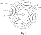
- fig. 8 the cross section along line A-A in fig. 4 is shown.
- the cylindrical contact surface 22 of the sealing element 20 has here been radially retracted by folding the cylindrical contact surface 22 outside of the lower housing section 11b.
- the fiber element structure 21 and the elastomeric material of the sealing element 20 is molded in the expanded state shown in fig. 7 .
- a sealing agent such as a water resistant polymer (silicon etc.) may be applied to the fiber element structure 21.
- the tool 1 further comprises a metal body 30 provided in the second sub-compartment 12b.
- the metal may be a bismuth metal or a bismuth alloy.
- Bismuth is a metal whose volume is larger when solidified than when molten. In other words, the density of the metal in liquid form is larger than the density of the metal in solid form.
- bismuth has a relatively low melting temperature, the melting temperature is approximately 270°C.
- the melting temperature of the metal body is therefore considerably lower than the melting temperature of the housing metal.
- the housing metal of the present invention is made of cast iron (melting point approximately 1200°C), cast steel (melting point approximately 1400°C - 1550°C), i.e. relatively cheaper metals compared with high grade steel metals used in the abovementioned prior art. It should be noted that also high grade steel metals may be used for the housing. In some applications, high temperature composite materials may be used for the housing.
- the metal is another metal or metal alloy whose volume is larger when solidified than when molten and with a melting temperature of the metal body lower than the melting temperature of the mandrel metal.
- Other such metals are germanium (melting point 940°C), gallium (melting point 30°C) or alloys thereof.
- bismuth alloy is the so-called lead-bismuth eutectic alloy comprising 44.5% lead and 55.5 % bismuth, having a melting point of 123.5°C.
- lead-bismuth eutectic alloy comprising 44.5% lead and 55.5 % bismuth, having a melting point of 123.5°C.
- Other lead/bismuth alloys are also suitable.
- bismuth alloys are tin/bismuth alloys or cupper/bismuth alloys, which will increase the melting temperature to a temperature above the melting temperature of bismuth alone. Such alloys may be preferred for example in high pressure and/or high temperature wells.
- suitable alloys may comprise more than two metals.
- the above metal body 30 may be a solid body inserted into the second sub-compartment 12b.
- the metal body 30 may poured into the second sub-compartment 12b in molten form, and subsequently allowed to solidify.
- the setting system 50 The setting system 50
- the tool 1 further comprises a setting system 50 used to set the tool 1 at the desired location in the well WE.
- the setting system 50 comprises a first sleeve holder 52a for holding the first end sleeve 24 of the expandable sealing element 20 outside of the lower housing section 11b and a second sleeve holder 52b for holding the second end sleeve 25 of the expandable sealing element 20 outside of the lower housing section 11b.
- the first sleeve holder 52a is secured to the lower housing section 11b and can be considered to be a part of the lower housing section 11b.
- the second sleeve holder 52b is longitudinally displaceable relative to the lower housing section 11b.
- the setting system 50 comprises a releasable securing element 54 for preventing such longitudinal displacement of the second sleeve holder 52b relative to the lower housing section 11b.
- the setting system 50 further comprises a spring 53 biased to longitudinally displace the second sleeve holder 52b relative to the lower housing section 11b towards the first sleeve holder 52a.
- the spring 53 is biased between the above-mentioned spring support 11c and the second sleeve holder 52b.
- the releasable securing element 54 is a meltable securing element.
- the setting system 50 comprises an auxiliary heater 55 for melting the meltable locking element 54.
- the setting system 50 comprising a main heater 51 which purpose is to melt the metal body 30.
- the main heater 51 may be located adjacent to the second sub-compartment 12b as indicated in fig. 4 , or may be located within the second sub-compartment 12b.
- the setting system 50 further comprises an auxiliary heater 59 located adjacent to the meltable securing element 58.
- the setting system 50 further comprises a control circuit 56a and a battery unit 56b provided in the upper housing section 11a for controlling and supplying electric energy to the main heater 51, the auxiliary heater 55 and the auxiliary heater 59 via electric wires provided within the wire channel 19.
- the run state in which the tool 1 is run or lowered into the well WE, is shown in fig. 1 and 4 .
- the tool 1 is also in this run state when transported from a manufacturing location to the well location and when handled topside.
- a compression band may be provided outside of the expandable sealing element 20 during transport and handling, to keep the sealing element 20 as shown in fig. 7 and for protecting the sealing element 20 from damages.
- the first sub-compartment 12a is filled with a pressurized gas. This pressurized gas will not move the piston 13, due to the metal body 30 in the second sub-compartment 12b.
- the main heater 51 is supplied with electric energy and the metal body will start to melt.
- the auxiliary heater 55 is also supplied with electric energy, causing the meltable securing element 54 to melt and thereby releasing the second sleeve holder 52b.
- the spring 53 will now displace the second sleeve holder 52b relative to the lower housing section 11b towards the first sleeve holder 52a, thereby causing or at least contributing to radial expansion of the expandable sealing element 20.
- the fiber element structure 21 will contribute to this radial expansion of the expandable sealing element 20, as the fiber element structure 21 will try to obtain its original shape ( fig. 7 ).
- the piston 13 When the metal body has been melted by the heater 51 the piston 13 will be allowed to move and the gas pressure in the first sub-compartment 12a will push the piston 13 down, causing the molten metal to be displaced from the second sub-compartment 12b into the second compartment 14, i.e. the expandable sealing element 20 will be filled with molten metal.
- the flow path for the molten metal from the second sub-compartment 12b via the fluid line 17 into the compartment 14 is indicated by a dashed arrow both in fig. 4 and fig. 5 .
- the expandable sealing element 20 has not been fully expanded by the movement of the sleeve holder 52b and the properties of the fiber reinforcement structure 21, the expandable sealing element 20 will become expanded as it becomes filled with molten metal.
- the expandable sealing element 20 will expand until it comes into contact with the inner surface of the well WE. It should be noted that the expandable sealing element 20 will not be damaged by the molten metal due to its heat resistant properties.
- the housing 11 (and hence the compartment 12) is longer than indicated in the drawings, as indicated by the break line C in fig. 4 and fig. 5 .
- the volume of the metal body 30 in fig. 4 may appear to be smaller than the volume of the compartment 14 in fig. 5 .
- the metal body 30 should have a volume sufficiently large to fill the entire compartment 14'.
- the height H20 is shorter in fig. the intermediate state than in the run state
- the height H13 is shorter in the intermediate state than in the run state
- the height H53 is longer in the intermediate state than in the run state.
- the solidified metal will also exert a force from the outer surface of the solidified metal to the inner surface of the well, thereby forming an anchoring of the tool relative to the well.
- the cylindrical contact surface 22 is brought into sealing contact with the inner surface of the well WE. Hence, the cylindrical contact surface 22 will prevent longitudinal fluid flow in the annulus between the outside of the housing 11 and the inside of the well WE. It is also shown that this cylindrical contact surface 22 has an extension in the longitudinal direction, as indicated by a height H22. Hence, the cylindrical contact surface 22 forms an area where friction between the cylindrical contact surface 22 and the well WE will prevent longitudinal movement of the tool 1 relative to the well WE.
- the outer diameter OD of the expandable sealing element 20 in the set state is considerably larger than the outer diameter OD of the of the expandable sealing element 20 in the run state (indicated in fig. 4 ).
- the outer diameter OD in the set state is approximately 2.5 times the outer diameter in the run state.
- the prior art HEX bridge plug has a corresponding OD in the set state is approximately 1.3 - 1.8 times the OD in the run state.
- the outer diameter OD of the cylindrical contact surface 22 of the expandable sealing element 20 in a free set state is 1.5 - 10% larger than the average inner diameter ID of the well WE, to ensure that the expandable sealing element 20 is allowed to expand properly into contact with the well and to ensure that the solidified metal is allowed to exert a force from the outer surface of the solidified metal to the inner surface of the well.
- control circuit 56a and the battery unit 56b will be retrieved to surface together with the upper housing section 11a.
- the upper housing section 11a and other parts of the well tool 1 is retrieved topside after setting of the lower housing section 11b and the expandable sealing element 20.
- the downhole well tool 1 may be a non-separatable tool, where the entire tool 1 will be left in the well WE.
- the centralizer 80 may have anchoring properties in addition to the centralizing properties, by equipping the centralizer with teeth 81 engaging the well WE in the intermediate and set states. Also here, the centralizer may be connected to the upper housing section 11a or to the lower housing section 11b. However, in high pressure wells, the centralizer is preferably connected to the lower housing section 11b.
- piston 13 is not necessarily an essential feature, as the molten metal may flow from the first compartment 12 to the second compartment 14 by means of gravity.
- control circuit 56a and the battery unit 56b may be located topside and is not a part of the tool 1.
- a chemical heater may be used instead of, or in addition to, an electric heater.
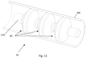
- the well tool 1 comprises three sealing elements 20, each sealing element 20 being filled with molten metal during the setting process and thereafter having allowed the molten metal to solidify.
Landscapes
- Engineering & Computer Science (AREA)
- Geology (AREA)
- Life Sciences & Earth Sciences (AREA)
- Mining & Mineral Resources (AREA)
- Geochemistry & Mineralogy (AREA)
- Fluid Mechanics (AREA)
- Environmental & Geological Engineering (AREA)
- General Life Sciences & Earth Sciences (AREA)
- Physics & Mathematics (AREA)
- Mechanical Engineering (AREA)
- Earth Drilling (AREA)
- Cable Accessories (AREA)
- Pressure Vessels And Lids Thereof (AREA)
- Laying Of Electric Cables Or Lines Outside (AREA)
- Devices For Use In Laboratory Experiments (AREA)
- Gasket Seals (AREA)
Claims (22)
- Outil de puits de fond de trou (1) pour sceller de manière permanente un puits de fond de trou (WE), ledit outil de puits de fond de trou (1) comprenant :- un boîtier (11) possédant une section de boîtier supérieure (11a) et une section de boîtier inférieure (11b) ;- un premier compartiment (12) prévu à l'intérieur du boîtier (11) ;caractérisé en ce que l'outil de puits de fond de trou (1) comprend :- un élément d'étanchéité extensible (20) prévu circonférentiellement à l'extérieur de la section de boîtier inférieure (11b), formant ainsi un second compartiment (14) radialement à l'intérieur de l'élément d'étanchéité extensible (20) et radialement à l'extérieur de la section de boîtier inférieure (11b) ;- un corps métallique (30) prévu à l'intérieur du premier compartiment (12) ;- un système de mise en place (50) comprenant un dispositif de chauffage (51) permettant la fusion du corps métallique (30) ;- une conduite de fluide (17) assurant une communication fluidique entre le premier compartiment (12) et le second compartiment (14) ;ledit outil de puits (1) étant conçu pour se trouver dans les états suivants :- un état passant, dans lequel l'élément d'étanchéité extensible (20) est radialement rétracté ;- un état intermédiaire, dans lequel le corps métallique (30) a été fondu par le dispositif de chauffage (51) et s'écoule du premier compartiment (12) au second compartiment (14) ; entraînant ainsi l'extension de l'élément d'étanchéité extensible (20) radialement jusqu'à être en contact avec le puits (WE) ;- un état durci, dans lequel le métal fondu provenant du corps métallique (30) est solidifié à l'intérieur du second compartiment (14).
- Outil de puits de fond de trou (1) selon la revendication 1, ledit élément d'étanchéité extensible (20) comprenant un matériau élastomère renforcé par une structure d'élément fibreux (21).
- Outil de puits de fond de trou (1) selon la revendication 2, ladite structure d'élément fibreux déterminant la forme de l'élément d'étanchéité extensible (20) dans l'état intermédiaire.
- Outil de puits de fond de trou (1) selon l'une quelconque des revendications précédentes, ledit élément d'étanchéité extensible (20) comprenant une surface de contact cylindrique (22) dans les états intermédiaire et durci.
- Outil de puits de fond de trou (1) selon la revendication 4, ledit diamètre externe (OD) de la surface de contact cylindrique (22) de l'élément d'étanchéité extensible (20) dans un état durci libre étant de 1,5 à 10 % plus grand que le diamètre interne moyen (ID) du puits (WE).
- Outil de puits de fond de trou (1) selon l'une quelconque des revendications précédentes, ledit outil de puits (1) comprenant un centreur (80) raccordé au boîtier (11).
- Outil de puits de fond de trou (1) selon l'une quelconque des revendications précédentes, ledit dispositif de chauffage (51) étant un dispositif de chauffage électrique.
- Outil de puits de fond de trou (1) selon l'une quelconque des revendications précédentes, ledit corps métallique (30) comprenant un métal ou un alliage métallique dont le volume est plus grand lorsqu'il est solidifié que lorsqu'il est fondu.
- Outil de puits de fond de trou (1) selon l'une quelconque des revendications précédentes, ledit corps métallique (30) comprenant un métal ou un alliage métallique possédant une température de fusion inférieure à la température de fusion du métal de boîtier.
- Outil de puits de fond de trou (1) selon l'une quelconque des revendications précédentes, ledit corps métallique (30) comprenant du bismuth ou un alliage de bismuth.
- Outil de puits de fond de trou (1) selon l'une quelconque des revendications précédentes, ladite section de boîtier supérieure (1 1a) étant raccordée de manière libérable à la section de boîtier inférieure (11b) par un élément de fixation libérable (18 ; 58).
- Outil de puits de fond de trou (1) selon l'une quelconque des revendications précédentes, ledit outil de puits de fond de trou (1) comprenant un piston (13) en prise de manière coulissante et étanche à l'intérieur du premier compartiment (12) pour déplacer le métal fondu du premier compartiment (12) au second compartiment (14) dans l'état intermédiaire.
- Outil de puits de fond de trou (1) selon la revendication 12, ledit piston (13) séparant le premier compartiment (12) en un premier sous-compartiment (12a) dans lequel le corps métallique (30) est prévu et un second sous-compartiment (12b) dans lequel un gaz sous pression est prévu.
- Outil de puits de fond de trou (1) selon l'une quelconque des revendications précédentes, ledit élément d'étanchéité extensible (20) comprenant un premier manchon d'extrémité (24) et un second manchon d'extrémité (25), ladite surface de contact cylindrique (22) étant située longitudinalement entre ledit premier manchon d'extrémité (24) et ledit second manchon d'extrémité (25).
- Outil de puits de fond de trou (1) selon la revendication 14, ledit système de mise en place (50) comprenant :- un premier support de manchon (52a) pour maintenir le premier manchon d'extrémité (24) à l'extérieur de la section de boîtier inférieure (11b) ;- un second support de manchon (52b) pour maintenir le second manchon d'extrémité (25) à l'extérieur de la section de boîtier inférieure (11b) ;- un ressort (53) sollicité pour déplacer longitudinalement le second support de manchon (52b) par rapport à la section de boîtier inférieure (11b) vers le premier support de manchon (52a) ;- un élément de fixation libérable (54) pour empêcher le déplacement longitudinal du second support de manchon (52b) par rapport à la section de boîtier inférieure (11b) dans l'état passant ;ledit élément de fixation libérable (54) étant libéré dans l'état intermédiaire.
- Outil de puits de fond de trou (1) selon la revendication 15, ledit élément de fixation libérable (54) étant un élément de fixation fusible, et ledit système de mise en place (50) comprenant un dispositif de chauffage auxiliaire (55) destiné à faire fondre ledit élément de verrouillage fusible (54).
- Outil de puits de fond de trou (1) selon la revendication 15 ou 16, ledit boîtier (11) comprenant un support de ressort (11c) pour supporter ledit ressort (53).
- Outil de puits de fond de trou (1) selon l'une quelconque des revendications précédentes, ladite section de boîtier supérieure (11a) et/ou ladite section de boîtier inférieure (11b) comprenant un canal de fil (19) pour guider un fil électrique vers le dispositif de chauffage auxiliaire (55) et/ou le dispositif de chauffage (51).
- Outil de puits de fond de trou (1) selon l'une quelconque des revendications précédentes, ledit système de mise en place (50) comprenant un circuit de commande (56a) et une unité de batterie (56b) prévue dans la section de boîtier supérieure (11a) pour commander l'alimentation en énergie électrique du dispositif de chauffage (51) et/ou des dispositifs de chauffage auxiliaires (55, 59).
- Procédé permettant la mise en place d'un outil de puits de fond de trou (1) selon l'une quelconque des revendications 1 à 19 dans un puits de fond de trou (WE), ledit procédé comprenant les étapes de :- abaissement de l'outil (1) comprenant le boîtier (11) à un emplacement souhaité dans le puits de fond de trou (WE) ;- extension de l'élément d'étanchéité extensible (20) prévu circonférentiellement à l'extérieur du boîtier (11) ;ledit procédé comprenant en outre les étapes de :- fourniture du métal fondu au second compartiment (14) à l'extérieur du boîtier (11) et à l'intérieur de l'élément d'étanchéité extensible (20) ; l'extension ainsi de l'élément d'étanchéité extensible (20) jusqu'à être en contact avec le puits de fond de trou (WE) ;- la permission au métal fondu de se solidifier à l'intérieur du second compartiment (14).
- Procédé selon la revendication 20, ledit outil de puits de fond de trou (1) étant un outil de puits de fond de trou (1) selon la revendication 13, et ladite étape d'alimentation en métal fondu comprenant les étapes de :- fusion d'un corps métallique (30) prévu à l'intérieur du premier compartiment (12) à l'intérieur du boîtier (11) ;- déplacement du piston (13) à l'intérieur du premier compartiment (12), amenant ainsi le métal fondu à s'écouler du premier compartiment (12) à l'intérieur du boîtier (11) au second compartiment (14) à l'extérieur du boîtier (11) et à l'intérieur de l'élément d'étanchéité extensible (20).
- Procédé selon la revendication 20 ou 21, ledit outil de puits de fond de trou (1) étant un outil de puits de fond de trou (1) selon la revendication 14, et
ladite étape d'extension de l'élément d'étanchéité extensible (20) comprenant en outre l'étape de :- réduction d'une distance longitudinale entre le premier manchon d'extrémité (24) de l'élément d'étanchéité extensible (20) et le second manchon d'extrémité (25) de l'élément d'étanchéité extensible (20), étendant ainsi radialement la surface de contact cylindrique (22) de l'élément d'étanchéité extensible (20) entre le premier manchon d'extrémité (24) et le second manchon d'extrémité (25).
Applications Claiming Priority (2)
| Application Number | Priority Date | Filing Date | Title |
|---|---|---|---|
| NO20210826A NO346976B1 (en) | 2021-06-25 | 2021-06-25 | Downhole well tool for permanently sealing a downhole well |
| PCT/EP2022/065057 WO2022268474A1 (fr) | 2021-06-25 | 2022-06-02 | Outil de puits de fond de trou et procédé pour sceller de manière permanente d'un puits de fond de trou |
Publications (2)
| Publication Number | Publication Date |
|---|---|
| EP4359639A1 EP4359639A1 (fr) | 2024-05-01 |
| EP4359639B1 true EP4359639B1 (fr) | 2025-04-23 |
Family
ID=82115495
Family Applications (1)
| Application Number | Title | Priority Date | Filing Date |
|---|---|---|---|
| EP22731637.9A Active EP4359639B1 (fr) | 2021-06-25 | 2022-06-02 | Outil de puits de fond de trou et procédé pour sceller de manière permanente d'un puits de fond de trou |
Country Status (8)
| Country | Link |
|---|---|
| US (1) | US12312900B2 (fr) |
| EP (1) | EP4359639B1 (fr) |
| BR (1) | BR112023027363A2 (fr) |
| CA (1) | CA3218497A1 (fr) |
| DK (1) | DK4359639T3 (fr) |
| MX (1) | MX2023014585A (fr) |
| NO (1) | NO346976B1 (fr) |
| WO (1) | WO2022268474A1 (fr) |
Family Cites Families (15)
| Publication number | Priority date | Publication date | Assignee | Title |
|---|---|---|---|---|
| US2363269A (en) * | 1939-07-29 | 1944-11-21 | Schlumberger Well Surv Corp | Method for sealing borehole casings |
| US5833001A (en) * | 1996-12-13 | 1998-11-10 | Schlumberger Technology Corporation | Sealing well casings |
| US6474414B1 (en) * | 2000-03-09 | 2002-11-05 | Texaco, Inc. | Plug for tubulars |
| US7455104B2 (en) * | 2000-06-01 | 2008-11-25 | Schlumberger Technology Corporation | Expandable elements |
| RU2191249C2 (ru) * | 2000-07-03 | 2002-10-20 | Институт горного дела - научно-исследовательское учреждение СО РАН | Пакер и способ его фиксации в скважине |
| GB2420361A (en) * | 2002-02-27 | 2006-05-24 | Canitron Systems Inc | Apparatus, casing and method for heating a material used for sealing faults within cement used for sealing an oil or gas well |
| NO318363B1 (no) | 2003-04-02 | 2005-03-07 | Bronnteknologiutvikling As | Anordning ved trekkbar broplugg |
| GB2480869B (en) * | 2010-06-04 | 2017-01-11 | Bisn Tec Ltd | Method and apparatus for use in well abandonment |
| EP3119981B1 (fr) * | 2014-03-20 | 2021-06-02 | Saudi Arabian Oil Company | Procédé et appareil permettant de sceller une zone de formation indésirable dans la paroi d'un puits de forage |
| NO341581B1 (en) * | 2015-09-17 | 2017-12-11 | Interwell Technology As | Sealing device for a well plug |
| EP3500722B1 (fr) * | 2016-08-19 | 2023-12-20 | BiSN Tec Ltd | Opérations de fond de trou relatives à des massifs de gravier en trou ouvert et outils destinés à être utilisés au cours de celles-ci |
| DK3631150T3 (da) * | 2017-05-24 | 2024-02-12 | Bisn Tec Ltd | Borehulsværktøjsudrulningsanordning med forbedret mulighed for fjernelse af varmeanordning og fremgangsmåder til anvendelse heraf |
| NO345012B1 (en) | 2018-01-30 | 2020-08-17 | Hydra Systems As | A method, system and plug for providing a cross-sectional seal in a subterranean well |
| WO2019194899A1 (fr) * | 2018-04-03 | 2019-10-10 | Schlumberger Technology Corporation | Procédés, appareil et systèmes pour créer des bouchons en alliage de bismuth pour des puits abandonnés |
| GB2583372B (en) * | 2019-04-26 | 2022-03-02 | Isol8 Holdings Ltd | Downhole sealing methods and apparatus |
-
2021
- 2021-06-25 NO NO20210826A patent/NO346976B1/en unknown
-
2022
- 2022-06-02 US US18/572,018 patent/US12312900B2/en active Active
- 2022-06-02 MX MX2023014585A patent/MX2023014585A/es unknown
- 2022-06-02 DK DK22731637.9T patent/DK4359639T3/da active
- 2022-06-02 CA CA3218497A patent/CA3218497A1/fr active Pending
- 2022-06-02 BR BR112023027363A patent/BR112023027363A2/pt unknown
- 2022-06-02 EP EP22731637.9A patent/EP4359639B1/fr active Active
- 2022-06-02 WO PCT/EP2022/065057 patent/WO2022268474A1/fr not_active Ceased
Also Published As
| Publication number | Publication date |
|---|---|
| WO2022268474A1 (fr) | 2022-12-29 |
| MX2023014585A (es) | 2023-12-15 |
| US20240287866A1 (en) | 2024-08-29 |
| EP4359639A1 (fr) | 2024-05-01 |
| US12312900B2 (en) | 2025-05-27 |
| BR112023027363A2 (pt) | 2024-03-12 |
| CA3218497A1 (fr) | 2022-12-29 |
| NO346976B1 (en) | 2023-03-20 |
| DK4359639T3 (da) | 2025-06-10 |
| NO20210826A1 (en) | 2022-12-27 |
Similar Documents
| Publication | Publication Date | Title |
|---|---|---|
| US12010970B2 (en) | Nano-thermite well plug | |
| US12129735B2 (en) | Tool for metal plugging or sealing of casing | |
| US11441384B2 (en) | Tool for metal plugging or sealing of casing | |
| EP3029261B1 (fr) | Procédés de déploiement d'outils pour assurer l'isolation eutectique de bouchons de puits de forage | |
| US3208530A (en) | Apparatus for setting bridge plugs | |
| WO2019151870A1 (fr) | Procédé, système et obturateur pour fournir un joint d'étanchéité en section transversale dans un puits souterrain | |
| US20100006289A1 (en) | Method and apparatus for sealing abandoned oil and gas wells | |
| GB2586796A (en) | Downhole barrier | |
| EP4232687B1 (fr) | Transmissions en liaison montante parallèles dans un réseau de communication sans fil | |
| EP3631150B1 (fr) | Ensemble de déploiement d'outil de fond de trou à séparation améliorée du dispositif de chauffage et procédés d'utilisation de celui-ci | |
| US12312900B2 (en) | Downhole well tool and method for permanently sealing a downhole well | |
| EP4308788B1 (fr) | Procédé de formation d'une barrière permanente dans un puits | |
| EP4359638B1 (fr) | Bouchon permanent pouvant être fraisé en fond de trou et procédé de réglage d'un bouchon permanent pouvant être fraisé en fond de trou | |
| WO2023031617A1 (fr) | Pièce rapportée pour tubage entièrement métal sur métal | |
| EP4232688B1 (fr) | Dispositif d'outil de puits pour le transport d'un mélange de génération de chaleur dans une canalisation de puits | |
| CA2665921A1 (fr) | Procede et appareil pour sceller des puits de petrole et de gaz abandonnes |
Legal Events
| Date | Code | Title | Description |
|---|---|---|---|
| STAA | Information on the status of an ep patent application or granted ep patent |
Free format text: STATUS: UNKNOWN |
|
| STAA | Information on the status of an ep patent application or granted ep patent |
Free format text: STATUS: THE INTERNATIONAL PUBLICATION HAS BEEN MADE |
|
| PUAI | Public reference made under article 153(3) epc to a published international application that has entered the european phase |
Free format text: ORIGINAL CODE: 0009012 |
|
| STAA | Information on the status of an ep patent application or granted ep patent |
Free format text: STATUS: REQUEST FOR EXAMINATION WAS MADE |
|
| 17P | Request for examination filed |
Effective date: 20240104 |
|
| AK | Designated contracting states |
Kind code of ref document: A1 Designated state(s): AL AT BE BG CH CY CZ DE DK EE ES FI FR GB GR HR HU IE IS IT LI LT LU LV MC MK MT NL NO PL PT RO RS SE SI SK SM TR |
|
| DAV | Request for validation of the european patent (deleted) | ||
| DAX | Request for extension of the european patent (deleted) | ||
| GRAP | Despatch of communication of intention to grant a patent |
Free format text: ORIGINAL CODE: EPIDOSNIGR1 |
|
| STAA | Information on the status of an ep patent application or granted ep patent |
Free format text: STATUS: GRANT OF PATENT IS INTENDED |
|
| GRAJ | Information related to disapproval of communication of intention to grant by the applicant or resumption of examination proceedings by the epo deleted |
Free format text: ORIGINAL CODE: EPIDOSDIGR1 |
|
| STAA | Information on the status of an ep patent application or granted ep patent |
Free format text: STATUS: REQUEST FOR EXAMINATION WAS MADE |
|
| INTG | Intention to grant announced |
Effective date: 20250121 |
|
| GRAP | Despatch of communication of intention to grant a patent |
Free format text: ORIGINAL CODE: EPIDOSNIGR1 |
|
| STAA | Information on the status of an ep patent application or granted ep patent |
Free format text: STATUS: GRANT OF PATENT IS INTENDED |
|
| INTC | Intention to grant announced (deleted) | ||
| GRAS | Grant fee paid |
Free format text: ORIGINAL CODE: EPIDOSNIGR3 |
|
| GRAA | (expected) grant |
Free format text: ORIGINAL CODE: 0009210 |
|
| STAA | Information on the status of an ep patent application or granted ep patent |
Free format text: STATUS: THE PATENT HAS BEEN GRANTED |
|
| INTG | Intention to grant announced |
Effective date: 20250226 |
|
| AK | Designated contracting states |
Kind code of ref document: B1 Designated state(s): AL AT BE BG CH CY CZ DE DK EE ES FI FR GB GR HR HU IE IS IT LI LT LU LV MC MK MT NL NO PL PT RO RS SE SI SK SM TR |
|
| REG | Reference to a national code |
Ref country code: GB Ref legal event code: FG4D |
|
| REG | Reference to a national code |
Ref country code: CH Ref legal event code: EP |
|
| REG | Reference to a national code |
Ref country code: DE Ref legal event code: R096 Ref document number: 602022013609 Country of ref document: DE |
|
| REG | Reference to a national code |
Ref country code: IE Ref legal event code: FG4D |
|
| REG | Reference to a national code |
Ref country code: DK Ref legal event code: T3 Effective date: 20250603 |
|
| REG | Reference to a national code |
Ref country code: NL Ref legal event code: FP |
|
| PGFP | Annual fee paid to national office [announced via postgrant information from national office to epo] |
Ref country code: DE Payment date: 20250522 Year of fee payment: 4 |
|
| PGFP | Annual fee paid to national office [announced via postgrant information from national office to epo] |
Ref country code: DK Payment date: 20250603 Year of fee payment: 4 |
|
| PGFP | Annual fee paid to national office [announced via postgrant information from national office to epo] |
Ref country code: NL Payment date: 20250605 Year of fee payment: 4 |
|
| PGFP | Annual fee paid to national office [announced via postgrant information from national office to epo] |
Ref country code: AT Payment date: 20250721 Year of fee payment: 4 |
|
| REG | Reference to a national code |
Ref country code: AT Ref legal event code: MK05 Ref document number: 1787918 Country of ref document: AT Kind code of ref document: T Effective date: 20250423 |
|
| PG25 | Lapsed in a contracting state [announced via postgrant information from national office to epo] |
Ref country code: FI Free format text: LAPSE BECAUSE OF FAILURE TO SUBMIT A TRANSLATION OF THE DESCRIPTION OR TO PAY THE FEE WITHIN THE PRESCRIBED TIME-LIMIT Effective date: 20250423 Ref country code: PT Free format text: LAPSE BECAUSE OF FAILURE TO SUBMIT A TRANSLATION OF THE DESCRIPTION OR TO PAY THE FEE WITHIN THE PRESCRIBED TIME-LIMIT Effective date: 20250825 Ref country code: ES Free format text: LAPSE BECAUSE OF FAILURE TO SUBMIT A TRANSLATION OF THE DESCRIPTION OR TO PAY THE FEE WITHIN THE PRESCRIBED TIME-LIMIT Effective date: 20250423 |
|
| REG | Reference to a national code |
Ref country code: LT Ref legal event code: MG9D |
|
| PG25 | Lapsed in a contracting state [announced via postgrant information from national office to epo] |
Ref country code: NO Free format text: LAPSE BECAUSE OF FAILURE TO SUBMIT A TRANSLATION OF THE DESCRIPTION OR TO PAY THE FEE WITHIN THE PRESCRIBED TIME-LIMIT Effective date: 20250723 Ref country code: GR Free format text: LAPSE BECAUSE OF FAILURE TO SUBMIT A TRANSLATION OF THE DESCRIPTION OR TO PAY THE FEE WITHIN THE PRESCRIBED TIME-LIMIT Effective date: 20250724 |
|
| PG25 | Lapsed in a contracting state [announced via postgrant information from national office to epo] |
Ref country code: PL Free format text: LAPSE BECAUSE OF FAILURE TO SUBMIT A TRANSLATION OF THE DESCRIPTION OR TO PAY THE FEE WITHIN THE PRESCRIBED TIME-LIMIT Effective date: 20250423 |
|
| PG25 | Lapsed in a contracting state [announced via postgrant information from national office to epo] |
Ref country code: BG Free format text: LAPSE BECAUSE OF FAILURE TO SUBMIT A TRANSLATION OF THE DESCRIPTION OR TO PAY THE FEE WITHIN THE PRESCRIBED TIME-LIMIT Effective date: 20250423 |
|
| PG25 | Lapsed in a contracting state [announced via postgrant information from national office to epo] |
Ref country code: HR Free format text: LAPSE BECAUSE OF FAILURE TO SUBMIT A TRANSLATION OF THE DESCRIPTION OR TO PAY THE FEE WITHIN THE PRESCRIBED TIME-LIMIT Effective date: 20250423 Ref country code: AT Free format text: LAPSE BECAUSE OF FAILURE TO SUBMIT A TRANSLATION OF THE DESCRIPTION OR TO PAY THE FEE WITHIN THE PRESCRIBED TIME-LIMIT Effective date: 20250423 |
|
| PG25 | Lapsed in a contracting state [announced via postgrant information from national office to epo] |
Ref country code: RS Free format text: LAPSE BECAUSE OF FAILURE TO SUBMIT A TRANSLATION OF THE DESCRIPTION OR TO PAY THE FEE WITHIN THE PRESCRIBED TIME-LIMIT Effective date: 20250723 |
|
| PG25 | Lapsed in a contracting state [announced via postgrant information from national office to epo] |
Ref country code: IS Free format text: LAPSE BECAUSE OF FAILURE TO SUBMIT A TRANSLATION OF THE DESCRIPTION OR TO PAY THE FEE WITHIN THE PRESCRIBED TIME-LIMIT Effective date: 20250823 |
|
| PG25 | Lapsed in a contracting state [announced via postgrant information from national office to epo] |
Ref country code: LV Free format text: LAPSE BECAUSE OF FAILURE TO SUBMIT A TRANSLATION OF THE DESCRIPTION OR TO PAY THE FEE WITHIN THE PRESCRIBED TIME-LIMIT Effective date: 20250423 |
|
| PG25 | Lapsed in a contracting state [announced via postgrant information from national office to epo] |
Ref country code: SM Free format text: LAPSE BECAUSE OF FAILURE TO SUBMIT A TRANSLATION OF THE DESCRIPTION OR TO PAY THE FEE WITHIN THE PRESCRIBED TIME-LIMIT Effective date: 20250423 |
|
| PG25 | Lapsed in a contracting state [announced via postgrant information from national office to epo] |
Ref country code: CZ Free format text: LAPSE BECAUSE OF FAILURE TO SUBMIT A TRANSLATION OF THE DESCRIPTION OR TO PAY THE FEE WITHIN THE PRESCRIBED TIME-LIMIT Effective date: 20250423 |
|
| PG25 | Lapsed in a contracting state [announced via postgrant information from national office to epo] |
Ref country code: EE Free format text: LAPSE BECAUSE OF FAILURE TO SUBMIT A TRANSLATION OF THE DESCRIPTION OR TO PAY THE FEE WITHIN THE PRESCRIBED TIME-LIMIT Effective date: 20250423 |
|
| REG | Reference to a national code |
Ref country code: DE Ref legal event code: R097 Ref document number: 602022013609 Country of ref document: DE |
|
| PG25 | Lapsed in a contracting state [announced via postgrant information from national office to epo] |
Ref country code: SK Free format text: LAPSE BECAUSE OF FAILURE TO SUBMIT A TRANSLATION OF THE DESCRIPTION OR TO PAY THE FEE WITHIN THE PRESCRIBED TIME-LIMIT Effective date: 20250423 |
|
| REG | Reference to a national code |
Ref country code: CH Ref legal event code: H13 Free format text: ST27 STATUS EVENT CODE: U-0-0-H10-H13 (AS PROVIDED BY THE NATIONAL OFFICE) Effective date: 20260127 |
|
| PG25 | Lapsed in a contracting state [announced via postgrant information from national office to epo] |
Ref country code: IT Free format text: LAPSE BECAUSE OF FAILURE TO SUBMIT A TRANSLATION OF THE DESCRIPTION OR TO PAY THE FEE WITHIN THE PRESCRIBED TIME-LIMIT Effective date: 20250423 |
|
| PG25 | Lapsed in a contracting state [announced via postgrant information from national office to epo] |
Ref country code: MC Free format text: LAPSE BECAUSE OF FAILURE TO SUBMIT A TRANSLATION OF THE DESCRIPTION OR TO PAY THE FEE WITHIN THE PRESCRIBED TIME-LIMIT Effective date: 20250423 |
|
| PG25 | Lapsed in a contracting state [announced via postgrant information from national office to epo] |
Ref country code: LU Free format text: LAPSE BECAUSE OF NON-PAYMENT OF DUE FEES Effective date: 20250602 |
|
| REG | Reference to a national code |
Ref country code: BE Ref legal event code: MM Effective date: 20250630 |
|
| PLBE | No opposition filed within time limit |
Free format text: ORIGINAL CODE: 0009261 |
|
| STAA | Information on the status of an ep patent application or granted ep patent |
Free format text: STATUS: NO OPPOSITION FILED WITHIN TIME LIMIT |
|
| REG | Reference to a national code |
Ref country code: CH Ref legal event code: L10 Free format text: ST27 STATUS EVENT CODE: U-0-0-L10-L00 (AS PROVIDED BY THE NATIONAL OFFICE) Effective date: 20260304 |
|
| PG25 | Lapsed in a contracting state [announced via postgrant information from national office to epo] |
Ref country code: RO Free format text: LAPSE BECAUSE OF FAILURE TO SUBMIT A TRANSLATION OF THE DESCRIPTION OR TO PAY THE FEE WITHIN THE PRESCRIBED TIME-LIMIT Effective date: 20250423 |
|
| 26N | No opposition filed |
Effective date: 20260126 |
|
| PG25 | Lapsed in a contracting state [announced via postgrant information from national office to epo] |
Ref country code: IE Free format text: LAPSE BECAUSE OF NON-PAYMENT OF DUE FEES Effective date: 20250602 |
|
| PG25 | Lapsed in a contracting state [announced via postgrant information from national office to epo] |
Ref country code: BE Free format text: LAPSE BECAUSE OF NON-PAYMENT OF DUE FEES Effective date: 20250630 |
|
| PG25 | Lapsed in a contracting state [announced via postgrant information from national office to epo] |
Ref country code: FR Free format text: LAPSE BECAUSE OF NON-PAYMENT OF DUE FEES Effective date: 20250623 |
|
| PG25 | Lapsed in a contracting state [announced via postgrant information from national office to epo] |
Ref country code: CH Free format text: LAPSE BECAUSE OF NON-PAYMENT OF DUE FEES Effective date: 20250630 |