EP4359681B1 - Adaptateur, en particulier pour un moteur à train d'engrenages, comprenant un arbre d'adaptateur, une partie d'embrayage et un palier, en particulier un palier à roulement - Google Patents
Adaptateur, en particulier pour un moteur à train d'engrenages, comprenant un arbre d'adaptateur, une partie d'embrayage et un palier, en particulier un palier à roulement Download PDFInfo
- Publication number
- EP4359681B1 EP4359681B1 EP22731194.1A EP22731194A EP4359681B1 EP 4359681 B1 EP4359681 B1 EP 4359681B1 EP 22731194 A EP22731194 A EP 22731194A EP 4359681 B1 EP4359681 B1 EP 4359681B1
- Authority
- EP
- European Patent Office
- Prior art keywords
- adaptor
- bearing
- claws
- region
- shaft
- Prior art date
- Legal status (The legal status is an assumption and is not a legal conclusion. Google has not performed a legal analysis and makes no representation as to the accuracy of the status listed.)
- Active
Links
Images


Classifications
-
- F—MECHANICAL ENGINEERING; LIGHTING; HEATING; WEAPONS; BLASTING
- F16—ENGINEERING ELEMENTS AND UNITS; GENERAL MEASURES FOR PRODUCING AND MAINTAINING EFFECTIVE FUNCTIONING OF MACHINES OR INSTALLATIONS; THERMAL INSULATION IN GENERAL
- F16D—COUPLINGS FOR TRANSMITTING ROTATION; CLUTCHES; BRAKES
- F16D1/00—Couplings for rigidly connecting two coaxial shafts or other movable machine elements
- F16D1/10—Quick-acting couplings in which the parts are connected by simply bringing them together axially
- F16D1/108—Quick-acting couplings in which the parts are connected by simply bringing them together axially having retaining means rotating with the coupling and acting by interengaging parts, i.e. positive coupling
- F16D1/112—Quick-acting couplings in which the parts are connected by simply bringing them together axially having retaining means rotating with the coupling and acting by interengaging parts, i.e. positive coupling the interengaging parts comprising torque-transmitting surfaces, e.g. bayonet joints
-
- F—MECHANICAL ENGINEERING; LIGHTING; HEATING; WEAPONS; BLASTING
- F16—ENGINEERING ELEMENTS AND UNITS; GENERAL MEASURES FOR PRODUCING AND MAINTAINING EFFECTIVE FUNCTIONING OF MACHINES OR INSTALLATIONS; THERMAL INSULATION IN GENERAL
- F16C—SHAFTS; FLEXIBLE SHAFTS; ELEMENTS OR CRANKSHAFT MECHANISMS; ROTARY BODIES OTHER THAN GEARING ELEMENTS; BEARINGS
- F16C35/00—Rigid support of bearing units; Housings, e.g. caps, covers
- F16C35/04—Rigid support of bearing units; Housings, e.g. caps, covers in the case of ball or roller bearings
- F16C35/06—Mounting or dismounting of ball or roller bearings; Fixing them onto shaft or in housing
- F16C35/07—Fixing them on the shaft or housing with interposition of an element
-
- F—MECHANICAL ENGINEERING; LIGHTING; HEATING; WEAPONS; BLASTING
- F16—ENGINEERING ELEMENTS AND UNITS; GENERAL MEASURES FOR PRODUCING AND MAINTAINING EFFECTIVE FUNCTIONING OF MACHINES OR INSTALLATIONS; THERMAL INSULATION IN GENERAL
- F16D—COUPLINGS FOR TRANSMITTING ROTATION; CLUTCHES; BRAKES
- F16D1/00—Couplings for rigidly connecting two coaxial shafts or other movable machine elements
- F16D1/10—Quick-acting couplings in which the parts are connected by simply bringing them together axially
- F16D1/108—Quick-acting couplings in which the parts are connected by simply bringing them together axially having retaining means rotating with the coupling and acting by interengaging parts, i.e. positive coupling
- F16D1/116—Quick-acting couplings in which the parts are connected by simply bringing them together axially having retaining means rotating with the coupling and acting by interengaging parts, i.e. positive coupling the interengaging parts including a continuous or interrupted circumferential groove in the surface of one of the coupling parts
-
- F—MECHANICAL ENGINEERING; LIGHTING; HEATING; WEAPONS; BLASTING
- F16—ENGINEERING ELEMENTS AND UNITS; GENERAL MEASURES FOR PRODUCING AND MAINTAINING EFFECTIVE FUNCTIONING OF MACHINES OR INSTALLATIONS; THERMAL INSULATION IN GENERAL
- F16D—COUPLINGS FOR TRANSMITTING ROTATION; CLUTCHES; BRAKES
- F16D11/00—Clutches in which the members have interengaging parts
- F16D11/14—Clutches in which the members have interengaging parts with clutching members movable only axially
-
- F—MECHANICAL ENGINEERING; LIGHTING; HEATING; WEAPONS; BLASTING
- F16—ENGINEERING ELEMENTS AND UNITS; GENERAL MEASURES FOR PRODUCING AND MAINTAINING EFFECTIVE FUNCTIONING OF MACHINES OR INSTALLATIONS; THERMAL INSULATION IN GENERAL
- F16C—SHAFTS; FLEXIBLE SHAFTS; ELEMENTS OR CRANKSHAFT MECHANISMS; ROTARY BODIES OTHER THAN GEARING ELEMENTS; BEARINGS
- F16C2361/00—Apparatus or articles in engineering in general
- F16C2361/61—Toothed gear systems, e.g. support of pinion shafts
-
- F—MECHANICAL ENGINEERING; LIGHTING; HEATING; WEAPONS; BLASTING
- F16—ENGINEERING ELEMENTS AND UNITS; GENERAL MEASURES FOR PRODUCING AND MAINTAINING EFFECTIVE FUNCTIONING OF MACHINES OR INSTALLATIONS; THERMAL INSULATION IN GENERAL
- F16D—COUPLINGS FOR TRANSMITTING ROTATION; CLUTCHES; BRAKES
- F16D11/00—Clutches in which the members have interengaging parts
- F16D2011/006—Locking or detent means, i.e. means to keep the clutch in engaged condition
-
- F—MECHANICAL ENGINEERING; LIGHTING; HEATING; WEAPONS; BLASTING
- F16—ENGINEERING ELEMENTS AND UNITS; GENERAL MEASURES FOR PRODUCING AND MAINTAINING EFFECTIVE FUNCTIONING OF MACHINES OR INSTALLATIONS; THERMAL INSULATION IN GENERAL
- F16D—COUPLINGS FOR TRANSMITTING ROTATION; CLUTCHES; BRAKES
- F16D2300/00—Special features for couplings or clutches
- F16D2300/08—Details or arrangements of sealings not provided for in group F16D3/84
Definitions
- the invention relates to an adapter, in particular for a geared motor, with an adapter shaft and a coupling part as well as a bearing, in particular a rolling bearing.
- a geared motor has an electric motor that drives a gearbox.
- the invention is based on the task of designing a geared motor as compact as possible.
- the object is achieved with the geared motor according to the features specified in claim 1.
- the advantage here is that the adapter is very compact. However, it features an interrupted bearing seat. Since the interrupted bearing seat is located in the claw area, and the claws are designed to be very rigid due to the high torque that must be transmitted, the bearing is held with sufficient stability.
- a circumferential recess in particular a
- a recess is formed on the adapter shaft.
- the advantage here is that, although the bearing seat is also interrupted at this point, the adapter shaft's bulges in the area of the recess are spaced apart from the inner ring of the bearing. These bulges are caused when the claws are elastically deflected, particularly when torque surges are transmitted.
- the region covered by the claws in the axial direction encompasses the second region and is spaced axially from the first region.
- the bearing seat includes both regions and the claws are spaced from the uninterrupted region.
- the axial direction is aligned parallel to the axis of rotation of the adapter shaft, in particular wherein the circumferential direction and/or the radial distance is or are related to this axis of rotation.
- the inner ring is axially limited on both sides by retaining rings.
- the advantage here is that the first bearing is designed as a fixed bearing.
- a first retaining ring is received in a first annular groove, in particular in a first annular groove which runs completely and/or continuously in the circumferential direction, of the adapter shaft and delimits the inner ring,
- the first annular groove is axially spaced from the first region and/or from the claws.
- a second retaining ring limits the inner ring, in particular on the side of the inner ring facing away from the first retaining ring in the axial direction,
- the second retaining ring is accommodated in a second annular groove.
- the second annular groove is designed with multiple interruptions in the circumferential direction, and/or the second annular groove is arranged in the second region. This advantageously results in a very compact adapter, since the inner ring of the bearing partially protrudes axially into the area of the claws.
- the second annular groove is formed in the claws of the adapter part and/or in the claws of the coupling part. This advantageously ensures that the retaining ring is securely held in the axial direction.
- the second annular groove is continuous in the circumferential direction and is incorporated into the coupling part.
- the bearing is designed as a fixed bearing.
- the advantage here is that the bearing is axially fixed.
- the advantage here is that the gear motor can be designed as compactly as possible.
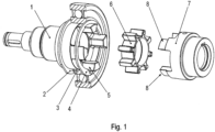
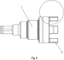
- the adapter shaft 1 has claws 5 at its axial end region facing the coupling part 7, which claws cover an axial region that overlaps the axial region covered by claws 8 of the coupling part 7.
- the axial direction is parallel to the rotational axis of the adapter shaft 1.
- the radial distances are related to the rotational axis of the adapter shaft 1.
- a damping part 6 is shaped as a plastic star.
- the damping part 6 has an annular base body on which radially projecting beam areas are formed.
- the base body is arranged radially within the claws 5 and 8.
- the radial distance area covered by the beam areas in the radial direction comprises or at least overlaps the radial distance area covered by the claws 5 of the adapter shaft 1 in the radial direction and the radial distance area covered by the claws 8 of the coupling part 7 in the radial direction.
- the damping part 6, in particular the beam areas, are arranged in the circumferential direction between the claws 5 of the adapter shaft 1 and the claws 8 of the coupling part 7.
- the beams are spherical in the radial direction.
- the wall thickness of the respective beam area measured in the circumferential direction, exhibits a local maximum in the radial direction.
- the area covered in the axial direction by the claws 5 of the adapter shaft 1 overlaps with the area covered in the axial direction by the claws 8 of the coupling part 7.
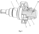
- the coupling part is placed on a rotor shaft 20, which projects through the coupling part 7 into a hollow area of the adapter shaft 1.
- the rotor shaft 20 is connected to the coupling part 7 in a rotationally fixed manner, in particular by means of a key connection.
- a bearing is placed on the adapter shaft 1, which preferably functions as a fixed bearing.
- the inner ring 3 of the bearing is placed on the adapter shaft 1 and axially limited on both sides by means of two retaining rings (2, 4).
- a first retaining ring 2 of the two retaining rings (2, 4) is provided in a first annular groove of the adapter shaft 1, wherein this first annular groove is spaced axially from the area axially covered by the claws 5 of the adapter shaft 1.
- the first annular groove is designed to be completely continuous in the circumferential direction.
- the second retaining ring 2 of the two retaining rings (2, 4) is provided in a second annular groove of the adapter shaft 1, wherein this second annular groove is arranged in the axial direction within the area covered by the claws 5 of the adapter shaft 1.
- the second annular groove is interrupted several times in the circumferential direction. This is because the claws 5 are spaced apart from one another in the circumferential direction, in particular evenly.
- the bearing seat is therefore designed with multiple interruptions in the circumferential direction.
- the bearing seat formed on the adapter shaft 1 for receiving the inner ring 3 thus covers an area in the axial direction which overlaps the area covered by the claws 5 of the adapter part 1 in the axial direction.
- the bearing seat is interrupted in a first area and uninterrupted in another area.
- the first section contributes 30% to 70% of the total axial width of the bearing seat.
- the other, uninterrupted section contributes the remaining portion.
- the first region contributes less than half, i.e. less than 50%, of the total axial width of the bearing seat is particularly preferred.
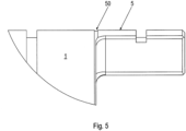
- a recess 50 is formed on the adapter part 1, which runs in the circumferential direction.
- the recess 50 is preferably machined by turning, in particular, as a recess.
- This recess 50 is arranged in the axial transition region between the first and the further region.
- the recess 50 in particular the recess, is arranged at the edge of the region covered by the claws 5 in the axial direction.
- the recess 50 delimits the area of the bearing seat interrupted in the circumferential direction from the rest of the bearing seat, i.e. from the area of the bearing seat which is uninterrupted in the circumferential direction.
- the recess 50 is arranged in the axial direction between the first annular groove for the first retaining ring 2 and the second annular groove for the second retaining ring 4.
- a second bearing is placed on the adapter shaft 1, which is accommodated in a second housing part 31 and functions as a loose bearing.
- the second housing part 31 is connected to a first housing part 30, in particular by means of screws.
- the outer ring of this first bearing is partially received in the first housing part 30 and partially in the wide housing part 31.
- the outer ring of the first bearing centers the first housing part 30 relative to the second housing part 31. Furthermore, a shaft seal 33 is accommodated in the first housing part 30, which seals against the adapter shaft 1.
- the first housing part can be connected to a transmission housing whose interior is at least partially filled with oil.
- the adapter shaft extends into the gearbox and is non-rotatably connected to a driving gear part of the gearbox.
- the outer diameter of the claws 8 of the coupling part 7 is smaller than the clear inner diameter of the second retaining ring 4, which is accommodated in the circumferentially interrupted annular groove of the adapter part 1.
- the driving toothed part is designed as one piece with the adapter shaft 1, i.e. as a single piece.
- the second retaining ring 4 is thus received in an annular groove of the coupling part 60 and limits the inner ring 3 accordingly.
- the inner ring 3 being delimited on the one hand by the first retaining ring 2, which is received in an annular groove of the adapter part 1, and on the other hand by the second retaining ring 4, which is received in an annular groove of the coupling part 60.
Landscapes
- Engineering & Computer Science (AREA)
- General Engineering & Computer Science (AREA)
- Mechanical Engineering (AREA)
- Mounting Of Bearings Or Others (AREA)
- Rolling Contact Bearings (AREA)
Claims (14)
- Adaptateur dévolu à un motoréducteur, comprenant un arbre adaptateur (1) et une partie d'accouplement (7), ainsi qu'un roulement,la partie adaptatrice dudit adaptateur étant munie de griffes (5), notamment de griffes (5) en saillie dans la direction axiale,la bague intérieure (3) du roulement étant emboîtée sur un siège de palier prévu sur l'arbre adaptateur (1),lequel siège de palier couvre, dans la direction axiale, une première région dans laquelle ledit siège de palier est de réalisation ininterrompue dans la direction du pourtour, et une seconde région dans laquelle ledit siège de palier est de réalisation discontinue dans la direction du pourtour,caractérisé par le faitqu'une seconde bague d'arrêt (2) délimite la bague intérieure (3) du côté de ladite bague intérieure tourné à l'opposé de la première bague d'arrêt (4) dans la direction axiale,ladite seconde bague d'arrêt (2) étant logée dans une seconde rainure annulaire.
- Adaptateur selon la revendication 1,
caractérisé par le faitqu'une pièce d'amortissement (6) est interposée entre les griffes de la partie d'accouplement (7) et les griffes (5) de l'arbre adaptateur (1),les zones rayonnées étant axialement disposées entre une griffe respective de ladite partie d'accouplement (7) et l'une des griffes de la partie adaptatrice. - Adaptateur selon l'une des revendications précédentes,
caractérisé par le fait
qu'un évidement circonférentiel (50), longeant la direction du pourtour, est façonné sur l'arbre adaptateur (1) dans la direction axiale, entre la première région et la seconde région. - Adaptateur selon l'une des revendications précédentes,
caractérisé par le fait que
la région, couverte par les griffes (5) dans la direction axiale, inclut la première région et est située à distance de la seconde région dans la direction axiale. - Adaptateur selon l'une des revendications précédentes,
caractérisé par le fait que
la direction axiale et orientée parallèlement à l'axe de rotation de l'arbre adaptateur (1). - Adaptateur selon l'une des revendications précédentes,
caractérisé par le fait que
la bague intérieure (3) est délimitée axialement, de part et d'autre, par des bagues d'arrêt. - Adaptateur selon l'une des revendications précédentes,
caractérisé par le faitqu'une première bague d'arrêt (4) est logée dans une première rainure annulaire de l'arbre adaptateur (1), et délimite la bague intérieure (3),ladite première rainure annulaire étant située à distance de la première région dans la direction axiale. - Adaptateur selon l'une des revendications précédentes,
caractérisé par le fait que
la seconde rainure annulaire est de réalisation discontinue dans la direction du pourtour, ladite seconde rainure annulaire étant située dans la seconde région. - Adaptateur selon l'une des revendications précédentes,
caractérisé par le fait que
la seconde rainure annulaire est pratiquée dans les griffes (5) de la partie adaptatrice et dans les griffes de la partie d'accouplement (7). - Adaptateur selon la revendication 8,
caractérisé par le fait que
la seconde rainure annulaire est de réalisation ininterrompue dans la direction du pourtour et est pratiquée dans la partie d'accouplement (7). - Adaptateur selon l'une des revendications précédentes,
caractérisé par le fait queledit adaptateur est doté d'un boîtier comprenant des première (30) et seconde parties,la première partie (30) du boîtier étant reliée à la seconde partie (31) dudit boîtier,sachant que la bague extérieure du roulement est logée dans lesdites première (30) et seconde parties du boîtier, et centre la première partie par rapport à la seconde (31). - Adaptateur selon l'une des revendications précédentes,
caractérisé par le fait que
le roulement est conçu comme un palier fixe. - Adaptateur selon l'une des revendications précédentes,
caractérisé par le fait queledit adaptateur est nanti d'un second roulementdont la bague extérieure est logée dans la première partie (30) du boîtier et dont la bague intérieure (3) est emboîtée sur l'arbre adaptateur (1). - Motoréducteur équipé d'un adaptateur conforme à l'une des revendications précédentes,
caractérisé par le fait queledit motoréducteur comporte un moteur électrique et une transmission,un arbre rotorique (20) étant relié à la partie d'accouplement (7) avec verrouillage rotatif, notamment au moyen d'une liaison clavetée,sachant que l'arbre adaptateur (1) est relié, avec verrouillage rotatif, à une partie dentée menante de la transmission ou est réalisé d'une seule pièce, notamment d'un seul tenant avec ladite partie.
Applications Claiming Priority (2)
| Application Number | Priority Date | Filing Date | Title |
|---|---|---|---|
| DE102021003176 | 2021-06-22 | ||
| PCT/EP2022/064776 WO2022268455A1 (fr) | 2021-06-22 | 2022-05-31 | Adaptateur, en particulier pour un moteur à train d'engrenages, comprenant un arbre d'adaptateur, une partie d'embrayage et un palier, en particulier un palier à roulement |
Publications (3)
| Publication Number | Publication Date |
|---|---|
| EP4359681A1 EP4359681A1 (fr) | 2024-05-01 |
| EP4359681B1 true EP4359681B1 (fr) | 2025-04-30 |
| EP4359681C0 EP4359681C0 (fr) | 2025-04-30 |
Family
ID=82100749
Family Applications (1)
| Application Number | Title | Priority Date | Filing Date |
|---|---|---|---|
| EP22731194.1A Active EP4359681B1 (fr) | 2021-06-22 | 2022-05-31 | Adaptateur, en particulier pour un moteur à train d'engrenages, comprenant un arbre d'adaptateur, une partie d'embrayage et un palier, en particulier un palier à roulement |
Country Status (5)
| Country | Link |
|---|---|
| US (1) | US12510120B2 (fr) |
| EP (1) | EP4359681B1 (fr) |
| CN (1) | CN117501026A (fr) |
| DE (1) | DE102022001913A1 (fr) |
| WO (1) | WO2022268455A1 (fr) |
Family Cites Families (11)
| Publication number | Priority date | Publication date | Assignee | Title |
|---|---|---|---|---|
| US3301614A (en) * | 1964-07-07 | 1967-01-31 | Walter D Haentjens | Bearing adapter |
| DE29915624U1 (de) * | 1999-09-04 | 1999-12-30 | Ktr Kupplungstechnik Gmbh, 48432 Rheine | Drehelastische Wellenkupplung |
| DE102009009459B4 (de) | 2009-02-18 | 2012-04-12 | Grundei Hebetische Verladetechnik Gmbh | Klauenkupplung |
| DE202011000964U1 (de) | 2011-04-21 | 2012-07-23 | Dewert Antriebs- Und Systemtechnik Gmbh | Elektromotorischer Linearantrieb |
| ITVI20130224A1 (it) | 2013-09-10 | 2015-03-11 | Svecom P E S R L | Supporto perfezionato per perni di estremita¿ di alberi |
| DE102015210227B4 (de) | 2015-06-03 | 2025-07-03 | Bayerische Motoren Werke Aktiengesellschaft | Antriebsstrang |
| DE102015115001B4 (de) * | 2015-09-07 | 2021-01-28 | Festo Ag & Co. Kg | Riemenscheiben-Baugruppe |
| DE102016117466B4 (de) | 2016-09-16 | 2024-12-05 | Festo Se & Co. Kg | Riemenscheiben-Baugruppe und Befestigungssystem |
| DE102019003546A1 (de) | 2018-06-08 | 2019-12-12 | Sew-Eurodrive Gmbh & Co. Kg | Adapter für einen Antrieb und Antrieb |
| ES3059501T3 (en) * | 2021-07-28 | 2026-03-20 | Sew Eurodrive Gmbh & Co Kg | Adapter series for geared motors, and method for producing an adapter |
| FR3136024B1 (fr) * | 2022-05-25 | 2024-07-12 | Renault Sas | Dispositif de couplage pour réducteur à deux rapports de vitesses |
-
2022
- 2022-05-31 WO PCT/EP2022/064776 patent/WO2022268455A1/fr not_active Ceased
- 2022-05-31 DE DE102022001913.2A patent/DE102022001913A1/de active Pending
- 2022-05-31 CN CN202280041259.3A patent/CN117501026A/zh active Pending
- 2022-05-31 EP EP22731194.1A patent/EP4359681B1/fr active Active
- 2022-05-31 US US18/573,507 patent/US12510120B2/en active Active
Also Published As
| Publication number | Publication date |
|---|---|
| DE102022001913A1 (de) | 2022-12-22 |
| US20240288035A1 (en) | 2024-08-29 |
| EP4359681C0 (fr) | 2025-04-30 |
| WO2022268455A1 (fr) | 2022-12-29 |
| US12510120B2 (en) | 2025-12-30 |
| CN117501026A (zh) | 2024-02-02 |
| EP4359681A1 (fr) | 2024-05-01 |
Similar Documents
| Publication | Publication Date | Title |
|---|---|---|
| DE10017801B4 (de) | Torsionsschwingungsdämpfer | |
| EP1511952B1 (fr) | Entrainement standard, gamme de fabrication a flasque intermediaire | |
| EP1298353B1 (fr) | Engrenage et son utilisation | |
| EP3791461A1 (fr) | Moteur électrique doté d'un arbre de rotor et d'un premier et d'un second palier | |
| AT518787B1 (de) | Zahnradanordnung | |
| DE102024104310A1 (de) | Getriebemotor | |
| EP4377589B1 (fr) | Série d'adaptateurs pour moteurs à engrenages et procédé de fabrication d'un adaptateur | |
| EP4359681B1 (fr) | Adaptateur, en particulier pour un moteur à train d'engrenages, comprenant un arbre d'adaptateur, une partie d'embrayage et un palier, en particulier un palier à roulement | |
| EP3538782B1 (fr) | Motoréducteur, comprenant une transmission entraînée par un moteur électrique | |
| EP3308055B1 (fr) | Transmission pourvue d'un carter et d'un engrenage planétaire | |
| EP3538783B1 (fr) | Motoréducteur présentant un engrenage entraîné par un moteur électrique | |
| EP3947998B1 (fr) | Assemblage par serrage comportant une bague de serrage montée sur un moyeu, en particulier une partie d'arbre creux, et dotée d'une vis, en particulier une vis de serrage, | |
| EP4323665B1 (fr) | Entraînement comprenant un moteur électrique, une boîte de vitesses et un boîtier adaptateur disposé entre le moteur électrique et la boîte de vitesses | |
| EP3948000B1 (fr) | Assemblage par serrage comportant une bague de serrage montée sur un moyeu, en particulier partie d'arbre creux, dotée d'une vis, en particulier une vis de serrage, | |
| EP4352374B1 (fr) | Ensemble avec un arbre, une bague intérieure d'un palier montée sur l'arbre et un moyeu attaché à l'arbre | |
| EP3947999B1 (fr) | Assemblage par serrage comportant une bague de serrage montée sur un moyeu, en particulier partie d'arbre creux, et dotée d'une vis, en particulier une vis de serrage, | |
| DE102025138134A1 (de) | Adapterwelle | |
| DE102025138136A1 (de) | Adapterwelle | |
| DE102025138135A1 (de) | Adapterwelle | |
| EP4702260A1 (fr) | Arbre d'adaptation | |
| DE102023003085A1 (de) | Getriebemotor, aufweisend ein Getriebe und einen Elektromotor, und Verfahren zur Herstellung von Varianten einer Baureihe von Getriebemotoren | |
| DE102024104576A1 (de) | Getriebemotor, welcher ein Getriebe, einen Adapter und einen Elektromotor umfasst | |
| EP4587725A1 (fr) | Ensemble palier comprenant un arbre, une partie boîtier et un palier, et engrenage comprenant un ensemble palier | |
| AT503331B1 (de) | Getriebe | |
| DE102023003079A1 (de) | Lageranordnung, aufweisend eine Welle, ein Gehäuseteil und ein Lager, und Getriebe mit Lageranordnung |
Legal Events
| Date | Code | Title | Description |
|---|---|---|---|
| STAA | Information on the status of an ep patent application or granted ep patent |
Free format text: STATUS: UNKNOWN |
|
| STAA | Information on the status of an ep patent application or granted ep patent |
Free format text: STATUS: THE INTERNATIONAL PUBLICATION HAS BEEN MADE |
|
| PUAI | Public reference made under article 153(3) epc to a published international application that has entered the european phase |
Free format text: ORIGINAL CODE: 0009012 |
|
| STAA | Information on the status of an ep patent application or granted ep patent |
Free format text: STATUS: REQUEST FOR EXAMINATION WAS MADE |
|
| 17P | Request for examination filed |
Effective date: 20240122 |
|
| AK | Designated contracting states |
Kind code of ref document: A1 Designated state(s): AL AT BE BG CH CY CZ DE DK EE ES FI FR GB GR HR HU IE IS IT LI LT LU LV MC MK MT NL NO PL PT RO RS SE SI SK SM TR |
|
| DAV | Request for validation of the european patent (deleted) | ||
| DAX | Request for extension of the european patent (deleted) | ||
| GRAP | Despatch of communication of intention to grant a patent |
Free format text: ORIGINAL CODE: EPIDOSNIGR1 |
|
| STAA | Information on the status of an ep patent application or granted ep patent |
Free format text: STATUS: GRANT OF PATENT IS INTENDED |
|
| INTG | Intention to grant announced |
Effective date: 20241219 |
|
| GRAS | Grant fee paid |
Free format text: ORIGINAL CODE: EPIDOSNIGR3 |
|
| GRAA | (expected) grant |
Free format text: ORIGINAL CODE: 0009210 |
|
| STAA | Information on the status of an ep patent application or granted ep patent |
Free format text: STATUS: THE PATENT HAS BEEN GRANTED |
|
| AK | Designated contracting states |
Kind code of ref document: B1 Designated state(s): AL AT BE BG CH CY CZ DE DK EE ES FI FR GB GR HR HU IE IS IT LI LT LU LV MC MK MT NL NO PL PT RO RS SE SI SK SM TR |
|
| REG | Reference to a national code |
Ref country code: CH Ref legal event code: EP Ref country code: GB Ref legal event code: FG4D Free format text: NOT ENGLISH |
|
| REG | Reference to a national code |
Ref country code: IE Ref legal event code: FG4D Free format text: LANGUAGE OF EP DOCUMENT: GERMAN |
|
| REG | Reference to a national code |
Ref country code: DE Ref legal event code: R096 Ref document number: 502022003793 Country of ref document: DE |
|
| U01 | Request for unitary effect filed |
Effective date: 20250512 |
|
| U07 | Unitary effect registered |
Designated state(s): AT BE BG DE DK EE FI FR IT LT LU LV MT NL PT RO SE SI Effective date: 20250516 |
|
| PGFP | Annual fee paid to national office [announced via postgrant information from national office to epo] |
Ref country code: CH Payment date: 20250601 Year of fee payment: 4 |
|
| U20 | Renewal fee for the european patent with unitary effect paid |
Year of fee payment: 4 Effective date: 20250818 |
|
| PG25 | Lapsed in a contracting state [announced via postgrant information from national office to epo] |
Ref country code: ES Free format text: LAPSE BECAUSE OF FAILURE TO SUBMIT A TRANSLATION OF THE DESCRIPTION OR TO PAY THE FEE WITHIN THE PRESCRIBED TIME-LIMIT Effective date: 20250430 |
|
| PG25 | Lapsed in a contracting state [announced via postgrant information from national office to epo] |
Ref country code: NO Free format text: LAPSE BECAUSE OF FAILURE TO SUBMIT A TRANSLATION OF THE DESCRIPTION OR TO PAY THE FEE WITHIN THE PRESCRIBED TIME-LIMIT Effective date: 20250730 Ref country code: GR Free format text: LAPSE BECAUSE OF FAILURE TO SUBMIT A TRANSLATION OF THE DESCRIPTION OR TO PAY THE FEE WITHIN THE PRESCRIBED TIME-LIMIT Effective date: 20250731 |
|
| PG25 | Lapsed in a contracting state [announced via postgrant information from national office to epo] |
Ref country code: PL Free format text: LAPSE BECAUSE OF FAILURE TO SUBMIT A TRANSLATION OF THE DESCRIPTION OR TO PAY THE FEE WITHIN THE PRESCRIBED TIME-LIMIT Effective date: 20250430 |
|
| PG25 | Lapsed in a contracting state [announced via postgrant information from national office to epo] |
Ref country code: HR Free format text: LAPSE BECAUSE OF FAILURE TO SUBMIT A TRANSLATION OF THE DESCRIPTION OR TO PAY THE FEE WITHIN THE PRESCRIBED TIME-LIMIT Effective date: 20250430 |
|
| PG25 | Lapsed in a contracting state [announced via postgrant information from national office to epo] |
Ref country code: RS Free format text: LAPSE BECAUSE OF FAILURE TO SUBMIT A TRANSLATION OF THE DESCRIPTION OR TO PAY THE FEE WITHIN THE PRESCRIBED TIME-LIMIT Effective date: 20250731 |
|
| PG25 | Lapsed in a contracting state [announced via postgrant information from national office to epo] |
Ref country code: IS Free format text: LAPSE BECAUSE OF FAILURE TO SUBMIT A TRANSLATION OF THE DESCRIPTION OR TO PAY THE FEE WITHIN THE PRESCRIBED TIME-LIMIT Effective date: 20250830 |
|
| PG25 | Lapsed in a contracting state [announced via postgrant information from national office to epo] |
Ref country code: SM Free format text: LAPSE BECAUSE OF FAILURE TO SUBMIT A TRANSLATION OF THE DESCRIPTION OR TO PAY THE FEE WITHIN THE PRESCRIBED TIME-LIMIT Effective date: 20250430 |
|
| PG25 | Lapsed in a contracting state [announced via postgrant information from national office to epo] |
Ref country code: CZ Free format text: LAPSE BECAUSE OF FAILURE TO SUBMIT A TRANSLATION OF THE DESCRIPTION OR TO PAY THE FEE WITHIN THE PRESCRIBED TIME-LIMIT Effective date: 20250430 |
|
| PG25 | Lapsed in a contracting state [announced via postgrant information from national office to epo] |
Ref country code: SK Free format text: LAPSE BECAUSE OF FAILURE TO SUBMIT A TRANSLATION OF THE DESCRIPTION OR TO PAY THE FEE WITHIN THE PRESCRIBED TIME-LIMIT Effective date: 20250430 |
|
| PG25 | Lapsed in a contracting state [announced via postgrant information from national office to epo] |
Ref country code: MC Free format text: LAPSE BECAUSE OF FAILURE TO SUBMIT A TRANSLATION OF THE DESCRIPTION OR TO PAY THE FEE WITHIN THE PRESCRIBED TIME-LIMIT Effective date: 20250430 |
|
| PLBE | No opposition filed within time limit |
Free format text: ORIGINAL CODE: 0009261 |
|
| STAA | Information on the status of an ep patent application or granted ep patent |
Free format text: STATUS: NO OPPOSITION FILED WITHIN TIME LIMIT |
|
| REG | Reference to a national code |
Ref country code: CH Ref legal event code: L10 Free format text: ST27 STATUS EVENT CODE: U-0-0-L10-L00 (AS PROVIDED BY THE NATIONAL OFFICE) Effective date: 20260311 |
|
| 26N | No opposition filed |
Effective date: 20260202 |
|
| PG25 | Lapsed in a contracting state [announced via postgrant information from national office to epo] |
Ref country code: IE Free format text: LAPSE BECAUSE OF NON-PAYMENT OF DUE FEES Effective date: 20250531 |