EP4360602A1 - Système et procédé de formation de saillies dans un substrat utilisé pour fabriquer des articles absorbants - Google Patents
Système et procédé de formation de saillies dans un substrat utilisé pour fabriquer des articles absorbants Download PDFInfo
- Publication number
- EP4360602A1 EP4360602A1 EP23206588.8A EP23206588A EP4360602A1 EP 4360602 A1 EP4360602 A1 EP 4360602A1 EP 23206588 A EP23206588 A EP 23206588A EP 4360602 A1 EP4360602 A1 EP 4360602A1
- Authority
- EP
- European Patent Office
- Prior art keywords
- area
- altered
- substrate
- nip
- areas
- Prior art date
- Legal status (The legal status is an assumption and is not a legal conclusion. Google has not performed a legal analysis and makes no representation as to the accuracy of the status listed.)
- Pending
Links
Images




Classifications
-
- B—PERFORMING OPERATIONS; TRANSPORTING
- B29—WORKING OF PLASTICS; WORKING OF SUBSTANCES IN A PLASTIC STATE IN GENERAL
- B29C—SHAPING OR JOINING OF PLASTICS; SHAPING OF MATERIAL IN A PLASTIC STATE, NOT OTHERWISE PROVIDED FOR; AFTER-TREATMENT OF THE SHAPED PRODUCTS, e.g. REPAIRING
- B29C67/00—Shaping techniques not covered by groups B29C39/00 - B29C65/00, B29C70/00 or B29C73/00
- B29C67/0048—Local deformation of formed objects
-
- A—HUMAN NECESSITIES
- A61—MEDICAL OR VETERINARY SCIENCE; HYGIENE
- A61F—FILTERS IMPLANTABLE INTO BLOOD VESSELS; PROSTHESES; DEVICES PROVIDING PATENCY TO, OR PREVENTING COLLAPSING OF, TUBULAR STRUCTURES OF THE BODY, e.g. STENTS; ORTHOPAEDIC, NURSING OR CONTRACEPTIVE DEVICES; FOMENTATION; TREATMENT OR PROTECTION OF EYES OR EARS; BANDAGES, DRESSINGS OR ABSORBENT PADS; FIRST-AID KITS
- A61F13/00—Bandages or dressings; Absorbent pads
- A61F13/15—Absorbent pads, e.g. sanitary towels, swabs or tampons for external or internal application to the body; Supporting or fastening means therefor; Tampon applicators
- A61F13/15577—Apparatus or processes for manufacturing
- A61F13/15707—Mechanical treatment, e.g. notching, twisting, compressing, shaping
-
- A—HUMAN NECESSITIES
- A61—MEDICAL OR VETERINARY SCIENCE; HYGIENE
- A61F—FILTERS IMPLANTABLE INTO BLOOD VESSELS; PROSTHESES; DEVICES PROVIDING PATENCY TO, OR PREVENTING COLLAPSING OF, TUBULAR STRUCTURES OF THE BODY, e.g. STENTS; ORTHOPAEDIC, NURSING OR CONTRACEPTIVE DEVICES; FOMENTATION; TREATMENT OR PROTECTION OF EYES OR EARS; BANDAGES, DRESSINGS OR ABSORBENT PADS; FIRST-AID KITS
- A61F13/00—Bandages or dressings; Absorbent pads
- A61F13/15—Absorbent pads, e.g. sanitary towels, swabs or tampons for external or internal application to the body; Supporting or fastening means therefor; Tampon applicators
- A61F13/15577—Apparatus or processes for manufacturing
- A61F13/15707—Mechanical treatment, e.g. notching, twisting, compressing, shaping
- A61F13/15723—Partitioning batts; Cutting
-
- B—PERFORMING OPERATIONS; TRANSPORTING
- B29—WORKING OF PLASTICS; WORKING OF SUBSTANCES IN A PLASTIC STATE IN GENERAL
- B29C—SHAPING OR JOINING OF PLASTICS; SHAPING OF MATERIAL IN A PLASTIC STATE, NOT OTHERWISE PROVIDED FOR; AFTER-TREATMENT OF THE SHAPED PRODUCTS, e.g. REPAIRING
- B29C59/00—Surface shaping of articles, e.g. embossing; Apparatus therefor
- B29C59/02—Surface shaping of articles, e.g. embossing; Apparatus therefor by mechanical means, e.g. pressing
- B29C59/04—Surface shaping of articles, e.g. embossing; Apparatus therefor by mechanical means, e.g. pressing using rollers or endless belts
- B29C59/046—Surface shaping of articles, e.g. embossing; Apparatus therefor by mechanical means, e.g. pressing using rollers or endless belts for layered or coated substantially flat surfaces
-
- B—PERFORMING OPERATIONS; TRANSPORTING
- B29—WORKING OF PLASTICS; WORKING OF SUBSTANCES IN A PLASTIC STATE IN GENERAL
- B29L—INDEXING SCHEME ASSOCIATED WITH SUBCLASS B29C, RELATING TO PARTICULAR ARTICLES
- B29L2031/00—Other particular articles
- B29L2031/48—Wearing apparel
- B29L2031/4871—Underwear
- B29L2031/4878—Diapers, napkins
-
- B—PERFORMING OPERATIONS; TRANSPORTING
- B29—WORKING OF PLASTICS; WORKING OF SUBSTANCES IN A PLASTIC STATE IN GENERAL
- B29L—INDEXING SCHEME ASSOCIATED WITH SUBCLASS B29C, RELATING TO PARTICULAR ARTICLES
- B29L2031/00—Other particular articles
- B29L2031/727—Fastening elements
- B29L2031/729—Hook and loop-type fasteners
Definitions
- the present disclosure relates generally to the field of unitary protrusion formation in substrates used to manufacture absorbent articles and more specifically to shaping altered areas of the substrate where unitary protrusions are formed.
- Unitary protrusion formation is employed when forming substrates that are used in manufacturing absorbent articles (e.g. diapers).
- the unitary protrusions formed in the substrate are used for various components of the absorbent article (e.g. fastener).
- Defects are common in conventional methods for unitary protrusion formation.
- a substrate is passed through a nip between a first device (e.g. anvil roll with multiple protrusion-shaped cavities) and a second device (e.g. source of vibrational energy) and is altered in the nip such that protrusions are formed in the substrate.
- An area of the substrate being altered in the nip varies as the substrate moves through the nip.
- a first area of the substrate is altered in the nip at a first time period after which a second area of the substrate is altered in the nip at a second time period.
- the change in the area being altered e.g.
- a first set of embodiments are disclosed for providing a method of altering a portion of a substrate.
- the method includes providing a first device including an outer surface.
- the method also includes providing a second device including a source of vibration energy.
- the method also includes forming a nip between the source of vibration energy and the outer surface.
- the method also includes conveying the substrate through the nip.
- the method also includes intermittently altering the portion of the substrate in the nip to create a pattern of altered areas forming a shape.
- the altered areas have a pattern balance that includes one or more of: an average area of the substrate altered in the nip is within a threshold range across the portion of the substrate; and a simple area of integral areas within the altered areas is within a threshold range across the portion of the substrate.
- a second set of embodiments are disclosed that are similar to the first set of embodiments, except the altered areas have a pattern balance that further includes one or more of: a rate of change of an average area of the substrate altered in the nip is less than a threshold value across the portion of the substrate; and a rate of change of the simple area of integral areas within the altered area is within a threshold range across the portion of the substrate.
- a third set of embodiments are disclosed that are similar to the first set of embodiments, except the altered areas have a pattern balance that is based on a width of integral areas within the altered area in a cross machine direction not exceeding a maximum width threshold value across the portion of the substrate.
- a fourth set of embodiments are disclosed for providing a method of creating protrusions in a portion of a substrate.
- the method includes providing a first device comprising an outer surface.
- the method also includes providing a second device comprising a source of vibration energy.
- the method also includes forming a nip between the source of vibration energy and the outer surface.
- the method also includes conveying the substrate through the nip.
- the method also includes continuously creating the protrusions in the portion of the substrate in the nip to create a continuous area of the protrusions.
- the method also includes flattening a portion of the continuous area of the protrusions to create intermittent areas of the protrusions in the substrate intermediate flattened portions.
- the method may also comprise cooling the source of vibrational energy or the first device.
- the method may also comprise that the second device is a rotary sonotrode, and the vibration energy is ultrasonic energy.
- the method may also comprise that the second device is a blade sonotrode, and the vibration energy is ultrasonic energy.
- the present disclosure is not limited to particular materials, reagents, reaction materials, manufacturing processes, or the like, as such can vary. It is also to be understood that the terminology used herein is for purposes of describing particular embodiments only and is not intended to be limiting. It is also possible in the present disclosure that steps can be executed in different sequence where this is logically possible.
- machine direction is used herein to refer to the direction of material flow through a process.
- relative placement and movement of material can be described as flowing in the machine direction through a process from upstream in the process to downstream in the process.
- cross direction is used herein to refer to a direction that is generally perpendicular to the machine direction.
- nip means a region between an outer surface of a first device (e.g. anvil roll with multiple protrusion-shaped cavities) and a second device (e.g. source of vibrational energy).
- a first device e.g. anvil roll with multiple protrusion-shaped cavities
- a second device e.g. source of vibrational energy
- altered area means a region of a substrate that is altered in the nip, defined by an outer perimeter minus an island area within the outer perimeter.
- island area means an area within the perimeter of the altered area that is not altered in the nip.
- integral area means a rectangular area within the altered area having a width within the altered area that extends in the CD between perimeter edges of the altered area and a fixed length in the MD.
- simple area means an area defined by an integral area based on a product of the width of the integral area in the CD and the fixed length of the integral area in MD.
- pattern of altered areas means a plurality of adjacent altered areas along a substrate.
- portion of a substrate means a region of the substrate that encompasses a plurality of adj acent altered areas and includes area outside the plurality of adj acent altered areas.
- nip area means an area of the substrate within the nip at a given time.
- nip length means a length of the nip area in the MD.
- nip width means a width of the nip area in the CD.
- average area means a sum of the simple areas of the integral areas within a nip area divided by the number of integral areas in the nip area.
- rate of change of the average area means a difference in the average area between two nip areas over the altered area.
- rate of change of the average area means a ratio of a difference in the average area between a first nip area and a second nip area divided by the average area of the first nip area, multiplied by 100.
- rate of change of the simple area means a difference in the simple area between two integral areas over the altered area.
- pattern balance means a condition of the altered area defined by one or more of: a deviation of the simple area between any two integral areas within the altered area is less than a threshold value; a deviation of the average area of any two nip areas within the altered area is less than a threshold value; the simple area of any integral area within the altered area is within a threshold range; and the average area of any nip area within the altered area is within a threshold range.
- non-symmetrical shape means a shape of the perimeter of the altered area which lacks corresponding points whose connecting lines are perpendicularly bisected by one of the CD or MD axes.
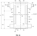
- FIG. 1A is a schematic top view illustrating an example of an absorbent article 100 manufactured with substrate having unitary protrusions, according to various embodiments.
- "absorbent article” is not limited to diapers, such as the tapered diaper 100T depicted in FIG. 1A .
- FIG. 1A shows a plan view of the diaper 100 with the portion of the diaper that faces toward a wearer oriented towards the viewer.
- the taped diaper 100T shown in FIG. 1A includes a chassis 102, first and second rear side panels 104 and 106; and first and second front side panels 108 and 110. As shown in FIG.
- the diaper 100 and the chassis 102 each include a first waist region 116, a second waist region 118, and a crotch region 119 disposed intermediate the first and second waist regions.
- the first waist region 116 may be configured as a front waist region
- the second waist region 118 may be configured as back waist region.
- the length of each of the front waist region, back waist region, and crotch region may be 1 ⁇ 3 of the length of the absorbent article 100.
- the absorbent article may also include a laterally extending front waist edge 120 in the front waist region 116 and a longitudinally opposing and laterally extending back waist edge 122 in the back waist region 118. To provide a frame of reference for the present discussion, the diaper 100T in FIG.
- the longitudinal axis 124 may extend through a midpoint of the front waist edge 120 and through a midpoint of the back waist edge 122.
- the lateral axis 126 may extend through a midpoint of a first longitudinal or right side edge 128 and through a midpoint of a second longitudinal or left side edge 130.
- the diaper 100 includes an inner, body facing surface 132.
- the chassis 102 may include a backsheet (not shown) and a topsheet 138.
- the chassis 102 may also include an absorbent assembly 140, including an absorbent core 142, disposed between a portion of the topsheet 138 and the backsheet (not shown).
- the diaper 100 may also include other features, such as leg elastics and/or leg cuffs, an elastic waist region, and/or flaps, e.g., side panels and/or ears, to enhance the fits around the legs and waist of the wearer, to enhance the fit around the legs of the wearer.
- the diaper 100 may also include various configurations of fastening elements to enable fastening of the front waist region 116 and the back waist region 118 together to form a closed waist circumference and leg openings once the diaper is positioned on a wearer.
- the diaper 100 may include first and second fastening members 162, 164, also referred to as tabs, connected with the first and second rear side panels 104, 106, respectively.
- the diaper may also include first and second front side panels 108, 110, that may or may not include fastening members.
- each side panel 104, 106 and/or fastening member 162 and 164 may form a portion of or may be permanently bonded, adhered or otherwise joined directly or indirectly to the chassis 102 laterally inward from the side edge 128 and 130, in one of the front waist region 116 or the back waist region 118.
- the fastening members 162, 164 may form a portion of or may be permanently bonded, adhered or otherwise joined directly or indirectly to the first and second rear panels 104, 106 at or adjacent the distal edge of the panel and/or the first and second front side panels 108 and 110 at or adjacent the distal edge of the side panel.
- fastening members and/or side panels may be assembled in various ways, such as disclosed for example, in U.S. Pat. No. 7,371,302 .
- the fastening members 162, 164 and/or side panels 104, 106, 108, 110 may also be permanently bonded or joined at or adjacent the side edges 128 and 130 of the chassis 102 in various ways, such as for example, by adhesive bonds, sonic bonds, pressure bonds, thermal bonds or combinations thereof, such as disclosed for example, U.S. Pat. No. 5,702,551 .
- the first fastening member 162 and/or the second fastening member 164 may include various types of releasably engageable fasteners.
- the first and second fastening members 162 and/or 164 may also include various types of refastenable fastening structures.
- the first and second fastening members 162 and 164 may include mechanical fasteners 166, in the form of hook and loop fasteners, hook and hook fasteners, macrofasteners, buttons, snaps, tab and slot fasteners, tape fasteners, adhesive fasteners, cohesive fasteners, magnetic fasteners, hermaphroditic fasteners, and the like.
- fastening systems and/or fastening members 162, 164 are discussed in U.S. Pat. Nos. 3,848,594 ; 4,662,875 ; 4,846,815 ; 4,894,060 ; 4,946,527 ; 5,151,092 ; 5,221,274 ; 6,251,097 ; 6,669,618 ; 6,432,098 ; and U.S. Patent Publication Nos. 2007/0078427 A1 and 2007/0093769 A1 .
- another example of a fastening system includes a Back Ear design (uBER), as discussed in U.S. Patent No. 9,533,067 .
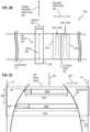
- FIG. 1B is a schematic cross-sectional side view illustrating an example of an ultrasonic forming apparatus 200 used to form unitary protrusions 209 in a portion or patch 215 of a substrate 211, according to various embodiments.
- the apparatus 200 may include a first device 201 and a second device 202 with a nip 204 formed therebetween.
- the first device 201 may be an anvil roll comprising multiple hook-shaped or otherwise shaped cavities or recesses 207, along an outer periphery thereof.
- the recesses 207 have a shape configured to produce the protrusions 209 which are suitable for use in a touch fastener of the absorbent article (e.g., fasteners 166).
- the second device 202 may be a source of vibrational energy 205, such as a blade sonotrode or a vibrating ultrasonic horn.
- the source of vibration energy 205 applies vibration energy to the substrate 211 intermittently or continuously.
- a substrate 206 may be positioned or passed through the nip 204.
- the substrate 206 may be, but need not be limited to, a film, sheet, web, nonwoven, composite, laminate, or other form, or may be portions of a film, sheet, web, nonwoven, laminate or substrate thermoplastic material, portions of which may be used as a component of a touch fastener, for instance on an absorbent article.
- touch fasteners may be attached to a "side tab" or "ear” that the consumer uses to secure the absorbent article the wearer. These tabs may be constructed with a piece of extensible material to allow the side tab to stretch and flex when attached or when the wearer moves.
- the touch fasteners may also be used in a two-point fastening system on an absorbent article, where the component is positioned on a landing zone or outer cover of the absorbent article.
- the present disclosure further contemplates the use of pre-formed film, sheet, web, composite, laminate, etc. as a substrate material.
- the second device 202 is positioned in close proximity to an outer surface 203 of the rotating first device 201 and in contact with the substrate 206 being processed.
- the first device 201 may also be a flat plate in other forms with the substate moving over the flat plate.
- the second device 202 may be vibrated at frequencies between about 50 Hz to about 50 kHz, as required.
- a portion of the substrate 206 in contact with, or in proximity with, the first device 201 and second device 202 may be softened by the vibration energy from the second device 202 and a desired portion of the substrate 206 may enter into the cavities 207 of the first device 201 to be shaped into protrusions 209 on the front surface of the film or sheet 211 as the first device 201 rotates in the direction indicated in FIG.
- This process may be referred to as rotary forming.
- Force may be exerted on the substrate 206 as it passes through the nip 204 to apply a requisite amount of pressure to the softened substrate 206 to assist its entry and filling of at least some of, or all of, the cavities 207.
- One example of the process is described in U.S. Pat. No. 8,784,722.
- the cavities 207 of the first device 201 are formed based on the determined altered area(s) in the embodiments of the present invention discussed herein. In some embodiments, the cavities 207 of the first device 201 are formed based on the shape of the determined altered area(s) of the embodiments of the present invention discussed herein. In one example embodiment, the cavities 207 are formed on the first device 201 within the outer perimeter of the altered area and the cavities 207 are not formed within the outer perimeter of the altered area for those areas corresponding to the island area(s) discussed herein.
- heat energy is imparted to the portion or patch 215 of the substrate 211 upstream of the nip 204 to heat the patch 215 of the substrate 211 to a temperature below a melting temperature of the patch 215 of the substrate 211, where the temperature below the melting temperature of the portion of the patch 215 is in a range of about 90 degrees C to about 160 degrees C.
- the apparatus 200 includes a means of cooling the source of vibrational energy 205 or the first device 201.
- FIG. 1C is a schematic perspective side view illustrating an example of an ultrasonic forming apparatus 200' used to form unitary protrusions 209 in a substrate 211, according to various embodiments.
- the apparatus 200' includes similar components as the apparatus 200, with the exception of the features discussed herein.
- the apparatus 200' of FIG. 1C features a rotary sonotrode as the second device 202' that is the source of ultrasonic energy.
- FIG. 1C is a schematic perspective side view illustrating an example of an ultrasonic forming apparatus 200' used to form unitary protrusions 209 in a substrate 211, according to various embodiments.
- the apparatus 200' includes similar components as the apparatus 200, with the exception of the features discussed herein.
- the apparatus 200' of FIG. 1C features a rotary sonotrode as the second device 202' that is the source of ultrasonic energy.
- FIG. 1C is a schematic perspective side view illustrating an example of an ultrasonic forming apparatus 200' used to form unitary protru
- the substrate 211 may include more than one layer 213a, 213b or more than one type of material. Additionally, the apparatus 200' may feature one or more substrate pre-heaters 220, 222 which may impart thermal energy to the substrate prior to the application of vibrational energy. The thermal energy may reduce the quantity of vibrational energy and/or time required to form a protrusion.
- FIG. 2A is a block diagram illustrating an example of the apparatus 200 used to form unitary protrusions 209 in the substrate 211, according to various embodiments.
- FIG. 2B is a block diagram illustrating an example of the apparatus 200 of FIG. 2A taken along the line 2B-2B, according to various embodiments.
- the substrate 211 extends in a machine direction (MD) 246 through the nip 204 of the apparatus 200.
- MD machine direction
- the substrate 211 extends within nip 204 by a length 243 in the MD 246.
- the MD length 243 is in a range from about 4 mm to about 8 mm.
- FIG. 2B depicts a top view of the substrate 211 passing through the nip 204. As shown in FIG. 2B , the substrate 211 extends within the nip 204 in the cross-machine direction 244 by a width 245.
- the CD width 245 is in a range from about 20 mm to about 45 mm. In an example embodiment, the CD width 245 is a pattern width of the altered area and the width of the substrate 211 may extend beyond the CD width 245 (e.g. between about 180 mm and about 220 mm).
- the width 245 is less than a width of the apparatus 200 in the CD 244 at the nip 204.
- the width 245 may be equal to a width of the apparatus 200 in the CD 244 at the nip 204.
- FIG. 2B depicts the nip area 247 which is an area of the substrate 211 within the nip 204 and based on a product of the MD length 243 and CD width 245.
- FIGS. 1B and 1C discuss apparatuses 200, 200' that form protrusions 209 over a certain portion (also known as the altered area) of the substrate 211 and does not form protrusions 209 beyond the altered area
- the apparatus 200, 200' forms protrusions 209 continuously over an entire area of the substrate 211, after which some portions of the substrate are flattened, which leaves intermittent areas of protrusions 209 that correspond to the altered area in the other embodiments.
- the flattening step is performed on a different manufacturing floor as the step of continuously forming protrusions 209 over the entire area of the substrate 211.
- an altered area 232 is a portion of the substrate 211 that is altered (e.g., over which protrusions 209 are formed) by the apparatus 200, 200'.
- the altered area(s) are registered on the substrate 211 in the MD 246 and the CD 244.
- the registration of the altered area(s) on the substrate is disclosed in U.S. Patent No. 9,763,836B2 ; U.S. Patent No. 6,764,563B2 ; U.S. Publication No. 2005/0125180A1 ; U.S. Patent No. 8,244,393B2 ; and U.S. Patent Publication No. 2019/0060135A1 which are incorporated by reference herein.
- not all of the substrate 211 that passes through the nip area 247 is altered by the apparatus 200, 200'.
- that portion of the substrate 211 that is altered by the apparatus 200, 200 is defined as an altered area of the substrate 211.
- protrusions 209 are only formed in the altered area of the substrate 211 and are not formed in regions of the substrate 211 outside the altered area. However, in other embodiments, protrusion 209 are continuously created over the substrate 211 after which certain portions of the substrate are flattened to leave intermittent areas that correspond to the altered area in the other embodiments.
- FIG. 2C is a block diagram illustrating an example of a top view of the nip area 247 of the substrate 211 in FIG. 2B , according to various embodiments.
- the altered area 232 is depicted in FIG. 2C and is defined as the area within an outer perimeter 250 along the substrate 211.
- not all of the substrate 211 within the nip area 247a is altered by the apparatus 200, 200', since not all of the substrate 211 within the nip area 247a is also within the outer perimeter 250 of the altered area 232.
- the entire nip area 247 of the substrate 211 may be within the outer perimeter 250 in which case the entire substrate 211 within the nip area 247 is altered by the apparatus 200, 200'.
- FIG. 2B depicts the altered area 232 which spans multiple nip areas 247a, 247b.
- FIG. 2B depicts the altered area 232 spanning two nip areas 247a, 247b for purposes of illustration, in other embodiments the altered area 232 may only span one nip area 247 or more than two nip areas 247a, 247b.
- FIGS. 2B and 2C depict one altered area 232, in other embodiments a pattern of more than one altered area 232 is provided along the portion 215 of the substrate 211.
- the altered area of the substrate 211 e.g. area of the substrate altered within the one or more nip areas 247
- One or more parameters were developed that are associated with the altered area of the substrate 211. These parameters can be determined across multiple altered areas 232 over the portion 215 of the substrate 211.
- a desired condition of the altered area(s) 232 known as pattern balance, is achieved when values of one or more of these parameters are within certain threshold ranges.
- the inventors of the present invention recognized that achieving this pattern balance with the altered area(s) 232 advantageously results in performance advantages with the apparatus 200, 200'.
- performance advantages include, but are not limited to: maintenance of sufficient contact forces in the nip 204, 204' to ensure sufficient flow of material to form the protrusions 209; and optimization of one or more control loops of the apparatus 200, 200' that ensure system parameters (e.g. frequency, amplitude, etc.) are maintained within desired threshold ranges.
- system parameters e.g. frequency, amplitude, etc.
- a first parameter is an average area of the substrate 211 that is altered within each nip area 247 over the altered area 232.
- one or more integral areas 235 are defined within each nip area 247.
- the integral areas 235 are rectangles that have a fixed length 264 in the MD 246 and a variable width 262 in the CD 244 that extends within the outer perimeter 250 of the altered area 232.
- the integral areas 235 are spaced apart by a fixed spacing 266 in the MD 246.
- values of the fixed spacing 266 and fixed length 264 are selected so that a desired number (e.g. between 2 - 10) of integral areas 235 are within each nip area 247.
- the integral areas 235 encompass areas of the substrate 211 that are altered within each nip area 247.
- the first parameter defines the average area of the substrate 211 altered within each nip area 247 as a sum of an area of the integral areas 235 within the nip area 247 divided by the number of integral areas 235 in the nip area 247.
- the area of each integral area 235 is defined as a simple area of the integral area 235.
- the area of the first integral area 235a is a product of the fixed length 264 and the first width 262a
- the area of the second integral area 235b is a product of the fixed length 264 and the second width 262b.
- any polygon can be used to define the integral areas 235 in which case the area formula for that polygon would be used to compute the simple area of each integral area and the average area of the substrate that is altered within each nip area.
- the average area of the substrate 211 that is altered within each nip area 247 over the altered area 232 is determined and is compared with a threshold value range (e.g. whether it is greater than a minimum threshold average area value and less than a maximum threshold average area value).
- a threshold value range e.g. whether it is greater than a minimum threshold average area value and less than a maximum threshold average area value.
- the minimum threshold average area value is about 15 mm 2 and the maximum threshold average area value is about 30 mm 2 .
- the minimum threshold average area value is about 10 mm 2 and the maximum threshold average area value is about 40 mm 2 .
- the ratio of the maximum threshold average area value to the minimum threshold average area value is no more than 4:1, preferably no more than 3:1, and more preferably no more than 2:1.
- these minimum and maximum threshold average area values exclude the leading edge and trailing edge portion of the altered area (where the average area value is zero for all altered area shapes).
- the average area of the substrate 211 will change based on the variable width 262 of those integral areas 235 within the nip area 247.
- most of the integral areas 235 have a variable width 262 of about 20 mm except for those integral areas 235 within an arm 239 of the altered area 232' (see FIGS. 3A and 3B ).
- the simple area of each integral area 235 within the nip area 247 is about 20 mm 2 and thus the average area within the nip area 247 is about 20 mm 2 .
- the average area within the nip 247 is no more than 40 mm 2 .
- the altered area 232 encompasses two nip areas 247a, 247b where two integral areas 235a, 235b are defined within the first nip area 247a and two integral areas 235c, 235d are defined within the second nip area 247b.
- the average area of the substrate 211 that is altered within each nip area 247a, 247b is determined.
- the average value of the substrate 211 that is altered within the first nip area 247a is based on a sum of the simple areas of the integral areas 235a, 235b divided by two (the number of integral areas 235a, 235b within the first nip area 247a).
- the average value of the substrate 211 that is altered within the second nip area 247b is based on a sum of the simple areas of the integral areas 235c, 235d divided by two (the number of integral areas 235c, 235d within the second nip area 247b).
- these determined values for the average area of the substrate 211 that is altered within the nip areas 247a, 247b are then each compared with the threshold value range.
- the altered area 232 has pattern balance.
- pattern balance is achieved across the altered areas 232.
- a second parameter is the simple area of each integral area 235 within the nip area(s) 247 over the altered area 232.
- the simple area of each integral area 235 in the nip area(s) 247 over the altered area 232 is determined.
- These simple area values are then compared with a threshold value range (e.g. whether it is greater than a minimum threshold simple area value and less than a maximum threshold simple area value).
- the minimum threshold simple area value is within a range that is similar to the minimum threshold average area value that was previously discussed.
- the maximum threshold simple area value is within a range that is similar to the maximum threshold average area value previously discussed. In the embodiment of FIG.
- the simple areas of the integral areas 235a, 235b are each determined and then each compared with the threshold value range.
- the simple areas of the integral areas 235a, 235b, 235c, 235d within the nip areas 247a, 247b over the altered area 232 are determined and then each compared with the threshold value range.
- the altered area 232 has achieved pattern balance.
- pattern balance is achieved across the altered areas 232.
- the second parameter can be a dimension of the integral area (e.g. variable width 262 in CD 244).
- pattern balance is achieved if the value of the variable width 262 in CD 244 of each integral area 235 of the altered area 232 is within a threshold range (e.g. greater than a minimum width and less than a maximum width).
- the minimum width is about 20 mm and the maximum width is about 45 mm.
- a third parameter is a rate of change of the average area of the substrate 211 that is altered between two nip areas 247 of the altered area 232.
- the average area for each nip area 247 is determined as previously discussed for the first parameter.
- the rate of change is based on a change in the average area value between any two nip areas 247 of the altered area 232.
- the rate of change is based on a change in the average area value between two adjacent or consecutive nip areas 247 of the altered area 232.
- This rate of change value is then assessed to determine whether it is less than a threshold value (e.g. whether it is less than a maximum rate of change value).
- the threshold value is an area value (e.g.
- the threshold value is a percentage value (e.g. a difference between the average area between a first and second nip area, divided by the average area at the first nip area, multiplied by 100).
- the maximum rate of change value is within +/-50% and more preferably within +50%/-25% of a nominal value throughout the altered area, excluding the leading and trailing edges.
- the maximum rate of change value for a rectangular shaped altered area may be +/-20 mm 2 area change (e.g., per mm of rotation of the outer surface 203).
- an inventive shape e.g. the altered area of FIG.
- the maximum rate of change value may be limited to a range from about -10 mm 2 to about +10 mm 2 (e.g. in-nip area per mm of rotation of the outer surface 203).
- a more balanced shaped altered area e.g. FIG. 3B
- these maximum rate of change values are dependent on the basic nip area 247, and thus altered areas with larger CD widths 262 will change the scale of these values.
- a rectangular altered area may have a maximum rate of change value between about - 100% and +100% of the full nip area 247 in mm 2 per mm of rotation of the outer surface 203.
- inventive shapes may have a maximum rate of change value between about -50% and +50%, or more preferably between about -25% and about +25% of the full nip area 247 in mm 2 per mm of rotation of the outer surface 203.
- the maximum rate of change value applies to the leading edge, a central region of said patch, and/or a trailing edge of the altered area.
- the rate of change is determined based on a deviation or change between the average area of the substrate 211 altered in the first nip area 247a and the average area of the substrate 211 altered in the second nip area 247b.
- the third parameter is expressed as a percentage.
- the rate of change is determined based on a difference between the average area in the first nip area 247a and the average area of the second nip area 247b divided by the average area in the first nip area 247a and multiplying this ratio by 100.
- the altered area 232 has achieved pattern balance. In some embodiments, where multiple altered areas 232 span the portion 215 of the substrate 211, if the determined rate of change is less than the threshold value across the multiple altered areas 232, pattern balance is achieved across the altered areas 232.
- a fourth parameter is a rate of change of the simple area between two integral areas 235 of the altered area 232.
- the simple area for each integral area 235 is determined as previously discussed for the second parameter.
- the rate of change is based on a change in the simple area value between any two integral areas 235 of the altered area 232 (e.g. between integral area 235a and integral area 235d of the altered area 232 in FIG. 2B ).
- the rate of change is based on a change in the simple area value between two adjacent or consecutive integral areas 235 of the altered area 232 (e.g. between integral areas 235a, 235b of the altered area 232 of FIG. 2B ).
- This rate of change value is then assessed to determine whether it is less than a threshold value (e.g. whether it is less than a maximum rate of change value).
- a threshold value e.g. whether it is less than a maximum rate of change value.
- the maximum rate of change value between the integral areas is similar to the maximum rate of change value between the average areas that was previously discussed.
- the maximum rate of change value between the integral areas is within a range that is similar to the maximum rate of change between the average areas that was previously discussed.
- the fourth parameter is expressed as a percentage.
- the rate of change is determined based on a difference between the simple area in the first integral area 235a and the simple area of the second integral area 235b divided by the simple area in the first integral area 235a and multiplying this ratio by 100.
- the altered area 232 has achieved pattern balance. In some embodiments, where multiple altered areas 232 span the portion 215 of the substrate 211, if the determined rate of change is less than the threshold value across the multiple altered areas 232, pattern balance is achieved across the altered areas 232.
- parameters are not limited to one or more of those four parameters and include any other parameters that can be developed to quantify the average area of the substrate 211 altered within each nip area 247 of the altered area 232.
- the entire area within the outer perimeter 250 of the altered area 232 is altered by the apparatus 200, 200'.
- the inventors of the present invention recognized that pattern balance cannot be achieved for some altered areas where the entire area within the outer perimeter 250 is altered by the apparatus 200, 200'.
- the inventors of the present invention developed a method for designating an area within the outer perimeter 250 that is not altered by the apparatus 200, 200' (known as an "island area") so that the altered area achieves pattern balance.
- the following embodiments discuss a method that is used to designate an island area within the outer perimeter, so that the altered area achieves pattern balance.
- FIG. 3A is an image illustrating an example of a top view of a first altered area 232' of the substrate 211 in FIG. 2B being altered by the apparatus 200, 200', according to various embodiments.
- the altered area 232' takes a shape 240 known as an "airpod".
- the shape 240 is a non-symmetrical shape, since the perimeter 250' of the altered area 232' lacks corresponding points whose connecting lines are perpendicularly bisected by one of the CD or MD axes. Specifically, as shown in FIG.
- an arm 239 of the perimeter 250' that extends in the CD 244 does not have corresponding points whose connecting lines are perpendicularly bisected by a CD axis 241.
- the shape 240 is symmetrical such that the perimeter of the altered area has corresponding points whose connecting lines are perpendicularly bisected by one of the CD or MD axes.
- the arm 239 of the altered area 232' extends beyond a fold line used in forming the absorbent article 100, as disclosed in U.S. Patent No. 9,265,674 and U.S. Patent No. 9,265,673 which are incorporated by reference herein.
- an entire area of the substrate 211 within the outer perimeter 250' of the altered area 232' is altered by the apparatus 200, 200'.
- a pair of adjacent nip areas 247a', 247b' are depicted in FIG. 3A , as well as integral areas 235 within the nip areas 247a', 247b'.
- pattern balance is not achieved by the altered area 232' since one or more of the parameter values are not within the respective threshold range for each parameter.
- a rate of change of the average area of the substrate 211 altered between the two nip areas 247a', 247b' exceeds the maximum rate of change threshold value.
- the average area of the substrate 211 that is altered in the second nip area 247b' is much larger than the average area of the substrate 211 that is altered in the first nip area 247a'.
- other parameters demonstrate pattern balance is not achieved by the altered area 232'.
- the value of the simple area of the integral areas 235 within the second nip area 247b' exceeds a maximum area value threshold.
- a rate of change of the simple area between integral areas 235 of the altered area 232' exceeds the maximum rate of change threshold value (e.g. note that the simple area of the integral areas 235 within the second nip area 247b' are much larger than the simple area of the integral areas 235 within the first nip area 247a').
- FIG. 3B is an image illustrating an example of a top view of a second altered area 232" of the substrate 211 in FIG. 2B being altered by the apparatus 200, 200', according to various embodiments.
- the altered area 232" takes a shape 240' that is similar to the shape 240 with the removed island area 252.
- the shape 240' is non-symmetrical for a similar reason as the shape 240 (e.g. arm 239).
- the altered area 232" is the same as the altered area 232' of FIG. 3A with the exception of an island area 252 (e.g. heart shaped) within the outer perimeter 250' that is not altered by the apparatus 200, 200'.
- an island area 252 e.g. heart shaped
- the altered area 232' has an increased width in the CD 244 from the first nip area 247a' to the second nip area 247b', resulting in one or more parameter values being outside the threshold range.
- the island area 252 of the altered area 232" of FIG. 3B offsets this increased width in the CD 244 of the altered area 232" between the first nip area 247a" and the second nip area 247b", resulting in the one or more parameter values being within the threshold range.
- nip areas 247a", 247b" are partially overlapping, the nip areas can be adjacent and non-overlapping as with the nip areas 247a', 247b' of FIG. 3A .
- a rate of change of the average area of the substrate 211 altered between the two nip areas 247a", 247b" is within the threshold range since the island area 252 reduced the average area of the substrate altered in the second nip area 247b" (as compared with the altered area 232').
- the simple area of the integral areas 235 within the altered area 232" are within the threshold range, since the island area 252 reduces the simple area of those integral areas 235 within the second nip area 247b" (which would otherwise exceed the threshold range).
- the third nip area 247c" of FIG. 3B does not include the island area 252 since the CD width 244 of the altered area 232" in the third nip area 247c" is not widened as in the nip area 247b" and thus the island area 252 need not extend into the third nip area 247c" to achieve pattern balance.
- FIG. 4A is an image illustrating an example of a top view of an altered area 232′′′ of the substrate 211 altered by the apparatus 200, 200', according to various embodiments.
- the altered area 232'" takes a shape 240" known as an "oval".
- the shape 240" is a non-symmetrical shape, since the perimeter 250" of the altered area 232'" lacks corresponding points whose connecting lines are perpendicularly bisected by one of the CD or MD axes. Specifically, as shown in FIG.
- an arm 239' of the perimeter 250" that extends in the CD 244 does not have corresponding points whose connecting lines are perpendicularly bisected by one of the CD or MD axes.
- the arm 239' of the altered area 232'" extends beyond a fold line used in forming the absorbent article 100, as disclosed in U.S. Patent No. 9,265,674 and U.S. Patent No. 9,265,673 which are incorporated by reference herein.
- an entire area of the substrate 211 within the outer perimeter 250'" of the altered area 232'" is altered by the apparatus 200, 200'.
- pattern balance is achieved by the altered area 232'" since one or more of the parameter values are within the respective threshold range for each parameter.
- a rate of change of the average area of the substrate 211 altered between the two nip areas 247a'", 247b'" is within a threshold range for the rate of change. Specifically, the average area of the substrate 211 that is altered in the second nip area 247b" is about equal to the average area of the substrate 211 that is altered in the first nip area 247a".
- the altered area 232' demonstrate pattern balance is achieved by the altered area 232'.
- the value of the simple area of the integral areas 235 within the nip areas 247a", 247b" are within a threshold value range.
- a rate of change of the simple area between integral areas 235 of the altered area 232'" is within a threshold range for the rate of change (since the simple area of the integral areas 235 are about equal across the nip areas 247a", 247b").
- FIG. 4B is an image illustrating an example of a top view of an altered area 232"" of the substrate 211 in FIG. 2B being altered by the apparatus 200, 200', according to various embodiments.
- the altered area 232"" takes a shape that is similar to the shape of the altered area 232'" with the removed island area 252'.
- the altered area 232"" is the same as the altered area 232'" of FIG. 4A with the exception of the island area 252' (e.g. heart shaped) within the outer perimeter 250'" that is not altered by the apparatus 200, 200'.
- the inventors recognized that designating the island area 252' within the outer perimeter 250'" does not achieve pattern balance with the altered area 232"" of FIG.
- the altered area 232'" has a relatively fixed increased width in the CD 244 from the first nip area 247a'" to the second nip area 247b'", resulting in one or more parameter values being within the threshold range of each parameter.
- the island area 252' of the altered area 232"" of FIG. 4B introduces variation in the width along the CD 244 of the altered area 232"" between the first nip area 247a"" and the second nip area 247b"", and thus results in parameter values falling outside the threshold range.
- the inventors of the present invention recognized that the island area 252' of FIG.
- the island area 252' is reshaped and/or repositioned and/or resized within the outer perimeter 250'" (e.g. closer to the top of the altered area 232"" where the CD width 262 widens into the arm 239') in order to maintain or improve the pattern balance of the altered area.
- FIG. 5 is a flow diagram that illustrates an example of a method 300 for altering a substrate with the apparatus 200, 200'.
- the flow diagram of FIG. 5 is depicted as integral steps in a particular order for purposes of illustration, in other embodiments one or more steps, or portions thereof, are performed in a different order, or overlapping in time, in series or in parallel, or are deleted, or one or more other steps are added, or the method is changed in some combination of ways.
- a first device is provided that includes an outer surface.
- the first device 201 is provided with the outer surface 203.
- a second device is provided that includes a source of vibration energy.
- the second device 202 is a blade sonotrode.
- the second device 202' is a rotary sonotrode.
- a nip is formed between the source of vibration energy and the outer surface of the first device.
- the nip 204 is formed between the second device 202 and the outer surface 203 of the first device 201.
- the nip 204' is formed between the second device 202' and the outer surface 203 of the first device 201.
- step 308 substrate is conveyed through the nip formed in step 306.
- the substrate 206 no protrusions 209 is conveyed in step 308 through the nip 204 ( FIG. 1B ) or the nip 204' ( FIG. 1C ).
- a portion of the substrate is intermittently altered in the nip to create a pattern of altered areas forming a shape.
- the portion 215 of the substrate 211 is intermittently altered in the nip 204, 204' to create a pattern of altered areas forming a shape.
- the altered area 232, 232", 232"" have a pattern balance.
- FIGS. 2B through 4B depict various altered areas, the altered areas created in step 310 are not limited to these particular altered areas and include any altered area(s) created on the portion of the substrate that achieve pattern balance.
- the pattern balance of the altered areas formed in step 310 is based on one or more of the previously discussed parameters having values that are within the threshold range for each parameter value over the altered areas.
- Result data will now be discussed, which demonstrates how the embodiments of the present invention improved the altered areas by achieving pattern balance.
- Graphs are now presented which demonstrate that the value of the one or more parameters used to demonstrate pattern balance of the altered areas were enhanced. In some embodiments, these parameter values were enhanced by adding an island area within the outer perimeter of the altered area. However, as discussed with respect to FIGS. 4A and 4B , in other embodiments pattern balance was achieved by not adding an island area within the outer perimeter. In still other embodiments, where the island area does not achieve pattern balance of the altered area, the island area can be reshaped, repositioned and/or resized in order to achieve pattern balance of the altered area.
- FIG. 6A is a graph 400 that illustrates an example of curves 410, 412, 414, 416 indicating an average area being altered in the nip area for different altered areas, according to various embodiments.
- the horizontal axis 402 is position along the MD 246 in units of millimeters (mm).
- the vertical axis 404 is the average altered area of the substrate in the nip area, in units of squared millimeters (mm 2 ).
- the first curve 410 indicates the average area value of the substrate 211 being altered in the nip areas 247' of the altered area 232' of FIG. 3A .
- the second curve 412 indicates the average area value of the substrate 211 being altered in the nip areas 247" of the altered area 232" of FIG.
- the second curve 412 indicates that the average area value is reduced and has less variation along the altered area 232", as compared to the altered area 232' along the same position along the MD 246 (e.g. between about 7 mm and 21 mm). This confirms that the island area 252 of the altered area 232" prevented the average area value from exceeding a maximum threshold value (e.g. 30 mm 2 ) and thus achieving pattern balance of the altered area 232" which was not attained with the altered area 232'.
- the third curve 416 indicates the average area value of the substrate 211 being altered in the nip areas 247'" of the altered area 232'" of FIG. 4A .
- the fourth curve 414 indicates the average area value of the substrate 211 being altered in the nip areas of a rectangular altered area (not shown).
- the fourth curve 418 serves as an ideal to compare with the curves for the non-rectangular active areas.
- FIG. 6B is a graph 450 that illustrates an example of curves 460, 462, 464, 466 indicating a rate of change of the average area being altered in the nip area for different altered areas, according to various embodiments.
- the horizontal axis 452 is position along the MD 246 in units of millimeters (mm).
- the vertical axis 454 is the rate of change of the average altered area of the substrate in the nip area, in units of squared millimeters (mm 2 ).
- the first curve 460 indicates the rate of change of the average area value of the substrate 211 being altered in the nip areas 247' of the altered area 232' of FIG. 3A .
- the second curve 462 indicates the rate of change of the average area value of the substrate 211 being altered in the nip areas 247" of the altered area 232" of FIG. 3B .
- the second curve 462 indicates that the rate of change is reduced along the altered area 232" compared to the altered area 232' along the same position along the MD 246 (e.g. between about 13 mm and 16 mm). This confirms that the island area 252 of the altered area 232" prevented the rate of change of the average area value from exceeding a maximum threshold value (e.g. 5 mm 2 ) and thus achieving pattern balance of the altered area 232" which was not attained with the altered area 232'.
- a maximum threshold value e.g. 5 mm 2
- the third curve 464 indicates the rate of change of the average area value of the substrate 211 being altered in the nip areas 247'" of the altered area 232′′′ of FIG. 4A .
- the fourth curve 466 indicates the rate of change of the average area value of the substrate 211 being altered in the nip areas of a rectangular altered area (not shown).
- the fourth curve 466 serves as an ideal (zero rate of change) to compare with the curves for the non-rectangular active areas.
- FIG. 7A is a graph 500 that illustrates an example of curves indicating an ultrasonic amplitude of the ultrasonic apparatus for different shaped altered areas, according to various embodiments.
- FIG. 7B is a graph 550 that illustrates an example of curves indicating an ultrasonic amplitude of the ultrasonic apparatus for different shaped altered areas, according to various embodiments.
- FIGS. 7A and 7B compare the ultrasonic amplitude response over time for different shaped altered areas.
- "Rectangle” indicates a purely rectangular altered area shape with sharp corners.
- Airpod is a rounded shaped altered area such as FIG. 3A , generally oval, with a large lateral protrusion arm 239 in the CD 244.
- “Sam Eagle” is a generally rectangular shaped altered area with a CD lateral protrusion. "Striped” is a segmented embodiment of the “Sam Eagle” shaped altered area, with unbonded regions. Horizontal axes 502, 552 in FIGS. 7A and 7B is time in units of seconds. Vertical axes 504, 554 in FIGS. 7A and 7B is relative amplitude (unitless).
- the curve 510 in FIG. 7A for the rectangular shaped altered area shows a large spike at the leading edge for over ten milliseconds. This high spike over a long duration is associated with leading edge burn thru and holes, as well as thin membrane regions intermediate the formed hooks.
- the central region of the rectangular altered area shows significant reduction in ultrasonic amplitude. This relatively low amplitude may be associated with poor hook formation. A result may be good hook formation at a leading edge, albeit with burn thru, and poor hook formation in a central region.
- the low amplitude on the trailing edge is associated with an over-reaction of the control system after the altered area rotates out of operative contact with the sonotrode 202. The oscillatory response observed may be indicative of a marginally stable amplitude control loop.
- Instabilities of this loop may be associated with generator faults and machine stops.
- curve 512 indicates that the airpod amplitude time response is relatively well behaved.
- the initial spike is slightly higher, due to the wide arm rotating in near the leading edge in this example. While the results are similar, these results are despite the wider in-nip width.
- the rounded leading edge results in a shorter duration exceeding 95% rated amplitude versus the rectangular altered area.
- the rounded shape results in somewhat less ringing, and a 10% reduction in the amplitude excursion from target as the altered area rotates out of operative contact with the sonotrode 202.
- the ultrasonic control system can maintain sufficiently close to target amplitude with a sufficiently balanced pattern, even when some portions of the shaped altered area are wider than a simple pattern.
- the curves 562 and 564 of FIG. 7B for the respective striped and Sam Eagle shaped altered areas demonstrate the problems with unbalanced patterns and sharp corners.
- the curve 564 for the Sam Eagle shaped altered area spikes over 100% amplitude at the CD protrusion region, yet the amplitude falls to 70% in the middle of the altered area. Such wide amplitude swings may exceed the operating process window, resulting in poorly or unformed hooks in the low amplitude regions and burn thru in the high amplitude regions.
- the striped altered area indicated by curve 562 is worse, with significant time variation in the amplitude, of less than 65% up to 95%. The large variations in the striped pattern force and amplitude response make sure patterns difficult to tune and adjust from a control system perspective.
- the pattern balance in general is a method to achieve a more constant process particularly for the amplitude and force variable illustrated as examples in FIGS. 7A and 7B .
- Managing the mechanical system to mitigate disturbance inputs to the multiple control loops may provide higher quality, fewer defects, fewer lines tops, and enable higher line rates.
- shaped and intermittent altered areas e.g. unitary fastener patches
- ultrasonic bonding is often considered capable of processing a wide variety of shaped patterns, without adverse effects.
- Rotary formation of unitary fasteners is quite different.
- the percentage of the substrate 211 which is in contact with the second device 202 is commonly above 50%, 75%, 80%, 90%, and even 95% of the substrate area.
- typical non-woven or film bond patterns in the disposable absorbent articles industry may be less than 10%, less than 5%, and less than 2.5% of the web width.
- Rotary formation of unitary fasteners may utilize much higher compression forces from the second device 202 (e.g. sonotrode) to the first device 201 (e.g. anvil). For example, forces of 1 kN, 2kN, 3kN, or even 5kN may be required for unitary rotary formation of protrusions 209 in a non-woven web. In contrast, 800N or 1000N are considered relatively high force levels for NW-NW lamination. As the force is higher, the power draw consumed from the second device 202 (e.g. sonotrode) is much higher. Thus, the control loops for the ultrasonics may be more susceptible to disturbances in rotary formation of protrusions 209 than in prior art bonding applications.
- the adjustment of the shape of the altered area 232 to achieve pattern balance using the embodiments of the present invention discussed herein advantageously reduces disturbances, especially force disturbances, and may become important to successful protrusion formation.
- Conventional methods disclose intermittent altered areas, rounded edges, and a variety of altered area shapes. These conventional methods do not disclose the techniques required to successfully convert such materials.
- Pattern balance of the altered area that reduces the disturbances from the substrate to the second device 202 may form one key method. For example, it is known in conventional methods to avoid sharp corners, substantially CD aligned leading and trailing edges, compound curves, and other shapes which may lead to high transient loadings.
- ultrasonic force may refer to an applied force or may be applied to a reaction force, where the reaction force is an induced load generated by compressing a thickness of substrate intermediate the second device 202 (e.g. sonotrode) and the first device 201 (e.g. a mold roll) with a certain gap.
- the force control mode may be achieved via a slow bandwidth outer loop position controller generating a setpoint based on a feedback signal from a force transducer.
- the sonotrode to anvil gap may be essentially constant.
- FIGS. 3A and 3B disclosed herein demonstrate improved pattern balance via positioning of a negative space (e.g. island area 252).
- the island area 252, or a region of the substrate 211 which is not operatively engaged by the second device 202 (e.g. source of ultrasonic energy 205) is disposed proximate a wider CD region of the altered are 232' (e.g. near the nip area 247b' in FIG. 3A ).
- conventional methods disclose forming regions not engaged by the second device 202, they do not disclose the relative disposition of such regions to distal protrusions and other elements of the altered area such that pattern balance is optimized.
- the practical effect of the placement of the island area 252 is to improve the pattern balance of the altered area 232" (relative to the altered area 232' without said island area 252).
- Placing the island area 252 adjacent to proximate regions of relatively increased CD altered area width advantageously reduces the peak reaction force experienced by the second device 202 (e.g. sonotrode).
- the second device 202 e.g. sonotrode
- various drawbacks may arise in the operation of the apparatus 200, 200' which will now be listed herein. For example, high peak forces may exceed the capacity of the second device 202 (e.g. sonotrode).
- these force disturbances may lead to dynamic performance errors in the amplitude, frequency, and/or power control loops of the apparatus 200, 200'.
- the force disturbances may induce mechanical resonance modes of the second device 202 (e.g. sonotrode) or the first device 201 (e.g. anvil) at critical frequencies.
- the force disturbances may induce position corrections of a sonotrode positioning loop, which may overreact to disturbances.
- disturbances in any of the control loops of the apparatus 200, 200', especially force and amplitude may result in burn-thru of the thin polymer membrane by the apparatus 200, 200'.
- Disturbances in any of the control loops of the apparatus 200, 200', especially the second device 202 (e.g. sonotrode) position, force and amplitude may result tearing of the thin polymer membrane by the apparatus 200, 200', in the absence of pattern balance of the altered area(s) in the substrate.
- the altered area may achieve pattern balance, meaning the size of the substrate region in operative engagement intermediate the second device 202 (e.g. sonotrode) and the first device 201 (e.g. mold roll) at any position of the process may be held within a range.
- Ultrasonics may be more robust than other bonding technologies, such as crimping.
- Pre-heat of substrates may enable a large operating range for rotary formation.
- a threshold range for the CD width 262 of the integral areas 235 may be between about 20mm to about 45mm to enable a process resulting in consistent protrusion 209 formation throughout an altered area. Maintaining a pattern balance ratio of maximum CD width 262 to minimum CD width 262 in the altered area may enable robust protrusion formation.
- leading and trailing edge regions may be excluded from the pattern balance.
- the pattern balance may be 100%, greater than 90%, greater than 50%, or greater than 30%.
- the threshold range for the CD width 262 of the altered area 232 may be increased by the shape.
- Altered areas in conventional methods were as narrow as 20 mm. Altered areas may contain island areas, or regions where no protrusions and/or no membrane are formed. These island areas may comprise discrete insignia, such as a heart shape.
- the MD location of the island area may be chosen to reduce the pattern imbalance. For example, a 6 mm wide island area may be used adjacent a CD protrusion from an altered area to reduce the effective CD width 262 of a 36 mm altered area to that of a 30 mm altered area.
- the island areas utilized for pattern balance may comprise MD, CD, or inclined lines or patterns.
- Altered areas may be larger and may contain more protrusions, which may better control rotation of the ear to improve fit in use.
- a portion of the altered area may protrude towards a distal region of the product, and may cross a fold line, which may be a e-folded edge of a diaper.
- the protrusions may then mitigate slippage of adjacent diapers in a stack or bag relative to each other, which may help retain a desirable primary package shape.
- Table 1 above provides data pertaining to the parameter values for assessing pattern balance with respect to the altered area 232' of FIG. 3A .
- a series of integral areas were drawn with MD spacing 266 of 1 mm.
- the CD width 262 of the integral area(s) at every 1mm increment was multiplied by the MD length 264 to determine a simple area.
- the running average in Table is the average area of a plurality of integral areas within the nip (e.g. 5 integral areas).
- the MD length 243 of the in-nip substrate was measured using a nip impression mold.
- the running average or average area is based on the number of integral areas in-nip MD length 243.
- the minimum and maximum threshold values for the average area or running average were used to define pattern balance.
- the pattern balance may also be evaluated based on the rate of change of the average area ("B2T area change" in Table 1) for a given MD slice dimension, which may or may not use a running average.
- B2T area change the rate of change for 1mm integral areas is in a range from -38% to +39% in the example above.
- the rate of change of the average area is +/- 20mm 2 per mm of mold roll rotation for rectangular substrates, and less than about 8mm 2 per mm of mold roll rotation for example inventive shapes.
- the rate of change may be evaluated at the leading and trailing edges.
- the rate of change for an approximate 10mm radius is about +/- 38% at the leading and trailing edges (arm is on the trailing edge in these examples, so the bottom is the leading edge).
- a distal protrusion from a central region of the substrate is desirable.
- the long thin arm in the above example Such distal regions may significantly upset the pattern balance, and may lead to large regions of poorly formed hooks.
- an island of non-woven is placed within the unitary formed fastener region.
- the island region may comprise a graphic or insignia, such as a heart.
- the island area may be used to affect an improved pattern balance via any of the methods disclosed here or via other methods of evaluating pattern balance. Note that the values shown in Table 1 are merely one example embodiment of different values for the different parameters used to assess pattern balance and thus these parameter values are not limited to the specific values provided in Table 1.
- FIG. 6A provides a complementary study, looking at the average area being altered in the nip area for four altered area shapes: a rectangular substrate, an oval with protruding CD arm (aka "Gru), an airpod, and an airpod with an island area (e.g. unformed heart shaped island feature).
- the curve 414 for the rectangular shaped altered area demonstrates a linear ramp with a high first derivative and infinite second derivative of area with respect to MD position in the altered area. MD position in the altered area may be considered a time domain for the purposes of this study.
- the curve 416 for the active area of FIG. 4A has an improved S-curve at leading and trailing edges due to the rounded shape, as do both of the altered area shapes of FIGS. 3A and 3B .
- the first and second derivatives of all three curves 410, 412, 416 are thus non-infinite second derivative values and the second derivative is limited to a smaller magnitude, creating and easier to follow process for the various control loops of the apparatus 200, 200'.
- the altered area 232' of FIG. 3A (curve 410) is worse for pattern balance due to the increased CD width 262, with a higher peak in-nip area (e.g. for the nip area 247b' depicted in FIG. 3A ).
- the altered area 232" of FIG. 3B mitigates this effect, reducing the peak in-nip area from over 35mm 2 to about 30 mm 2 .
- the full area under the curve for in-nip area is also reduced, thereby reducing the energy required from the source of ultrasonic energy 205 of the apparatus 200, 200'.
- FIG. 6B shows a first derivative of FIG. 6A with respect to machine position, which again is analogous to a time domain.
- the rectangular altered area represented by curve 466 has a clearly higher peak in-nip area rate of change (e.g., 20 mm 2 _nip_area / mm_MD_position).
- the rounded leading edge of the altered areas of FIGS. 3A, 3B and 4A reduces the leading edge rate of area change to under 10 mm 2 /mm and under 5 mm 2 /mm at the trailing edge for the three altered areas of FIGS. 3A, 3B and 4A .
- 3A, 3B and 4A is held under 8mm 2 /mm at the CD protrusion of each pattern.
- the island area 252 makes a small improvement to the rate of change of in-nip area, from about 8 to about 6 mm 2 /mm for the altered area 232' without the island area 252 and the altered area 232" with the island area 252.
- a continuous patch or a plurality of first discrete patches of protrusions 209 are made in the substrate 211 via the process of positioning the substrate intermediate the second device 202 (e.g. a sonotrode) and the first device 201 (e.g. a mold roll).
- the first device 201 e.g. a mold roll.
- a subset of the continuous protrusion patch formed may then be converted back into a substrate region without protrusions 209 by crushing, flattening, compression, heating, melting, shearing, shaving, burning, ultrasonic energy, a combination of said means, or other means.
- the resulting protrusion patch may thus have a virtually unconstrained shape.
- the continuous formation of a plurality of protrusions may enable higher line rates, more consistent protrusion formation, eliminate leading and trailing edge effects, more consistent hook extraction from a mold roll, or provide other process benefits.
- Certain intermittent patterns may provide similar benefits, which may include pattern balance, short MD gaps in the pattern, low rates of change in process variables which may include ultrasonic amplitude, ultrasonic compression force, ultrasonic shear force, ultrasonic frequency, ultrasonic power, or other process variables.
- the second step may comprise a compression roller with a suitable patch shape against an anvil roll, either of which may be heated.
- the second step may comprise a blade or rotary sonotrode against an anvil.
- the second step may comprise heating or stamping in a cyclic operation, which may utilize a rotating or reciprocating tool.
- the heating may comprise a heated roll, convective heat transfer from a first side, convective heat transfer from a second side, radiative heat transfer, or a plurality of methods.
- the crushed regions may be returned to a film or membrane.
- the crushed protrusions may be formed into a smooth surface or provided with a surface finish.
- the surface finish may comprise a pattern, a leatherlike appearance, assets of ridges, or other three dimensional effects.
- the region may form a cross network of raised protrusions, such as a cross-hatch diamond shape, which may reinforce and/or highlight said hook patch.
- the crushing process may be by a pressure bond, a heated roller, an ultrasonic sonotrode, a combination of said means, or an alternate method.
- Such post-processing may be after stripping the substrate with formed protrusions from a mold roll.
- the post-processing may use the stripper roll as a patterned or mating roll for a shaped pattern.
Landscapes
- Engineering & Computer Science (AREA)
- Health & Medical Sciences (AREA)
- Mechanical Engineering (AREA)
- Heart & Thoracic Surgery (AREA)
- Epidemiology (AREA)
- Biomedical Technology (AREA)
- Manufacturing & Machinery (AREA)
- Vascular Medicine (AREA)
- Life Sciences & Earth Sciences (AREA)
- Animal Behavior & Ethology (AREA)
- General Health & Medical Sciences (AREA)
- Public Health (AREA)
- Veterinary Medicine (AREA)
- Slide Fasteners, Snap Fasteners, And Hook Fasteners (AREA)
Applications Claiming Priority (1)
| Application Number | Priority Date | Filing Date | Title |
|---|---|---|---|
| US202263381607P | 2022-10-31 | 2022-10-31 |
Publications (1)
| Publication Number | Publication Date |
|---|---|
| EP4360602A1 true EP4360602A1 (fr) | 2024-05-01 |
Family
ID=88600638
Family Applications (1)
| Application Number | Title | Priority Date | Filing Date |
|---|---|---|---|
| EP23206588.8A Pending EP4360602A1 (fr) | 2022-10-31 | 2023-10-30 | Système et procédé de formation de saillies dans un substrat utilisé pour fabriquer des articles absorbants |
Country Status (2)
| Country | Link |
|---|---|
| US (1) | US20240140048A1 (fr) |
| EP (1) | EP4360602A1 (fr) |
Citations (25)
| Publication number | Priority date | Publication date | Assignee | Title |
|---|---|---|---|---|
| US3848594A (en) | 1973-06-27 | 1974-11-19 | Procter & Gamble | Tape fastening system for disposable diaper |
| US4662875A (en) | 1985-11-27 | 1987-05-05 | The Procter & Gamble Company | Absorbent article |
| US4846815A (en) | 1987-01-26 | 1989-07-11 | The Procter & Gamble Company | Disposable diaper having an improved fastening device |
| US4894060A (en) | 1988-01-11 | 1990-01-16 | Minnesota Mining And Manufacturing Company | Disposable diaper with improved hook fastener portion |
| US4946527A (en) | 1989-09-19 | 1990-08-07 | The Procter & Gamble Company | Pressure-sensitive adhesive fastener and method of making same |
| US5151092A (en) | 1991-06-13 | 1992-09-29 | The Procter & Gamble Company | Absorbent article with dynamic elastic waist feature having a predisposed resilient flexural hinge |
| US5221274A (en) | 1991-06-13 | 1993-06-22 | The Procter & Gamble Company | Absorbent article with dynamic elastic waist feature having a predisposed resilient flexural hinge |
| US5702551A (en) | 1996-04-03 | 1997-12-30 | The Procter & Gamble Company | Method for assembling a multi-piece absorbent article |
| US6251097B1 (en) | 1997-09-04 | 2001-06-26 | The Procter & Gamble Company | Absorbent article fastening device |
| US6432098B1 (en) | 1997-09-04 | 2002-08-13 | The Procter & Gamble Company | Absorbent article fastening device |
| US6669618B2 (en) | 2001-12-21 | 2003-12-30 | The Procter & Gamble Company | Method of dynamically pre-fastening a disposable absorbent article having a slot-and-tab fastening system |
| US6764563B2 (en) | 1997-12-19 | 2004-07-20 | The Procter & Gamble Company | Registration system for phasing simultaneously advancing webs of material having variable pitch lengths |
| US20050125180A1 (en) | 2003-12-09 | 2005-06-09 | Miller Charles P. | Method and system for registering pre-produced webs with variable pitch length |
| US20070078427A1 (en) | 2005-09-30 | 2007-04-05 | Raycheck Jeromy T | Anti-pop open macrofasteners |
| US20070093769A1 (en) | 2005-09-30 | 2007-04-26 | Kline Mark J | Fastening system having multiple engagement orientations |
| US7371302B2 (en) | 2002-07-23 | 2008-05-13 | The Procter & Gamble Company | Method for forming fastening members |
| US20100180407A1 (en) * | 2009-01-20 | 2010-07-22 | Rocha Gerald | Method And Apparatus For Producing Hook Fasteners |
| US8244393B2 (en) | 2009-09-10 | 2012-08-14 | The Procter & Gamble Company | System and methods for registering a controlled web to a pitched unit operation |
| US9265674B2 (en) | 2013-07-29 | 2016-02-23 | Kimberly-Clark Worldwide, Inc. | Absorbent article having a fastening system with low stiffness |
| US9265673B2 (en) | 2013-07-29 | 2016-02-23 | Kimberly-Clark Worldwide, Inc. | Absorbent article having a fastening system |
| US9533067B2 (en) | 2013-05-03 | 2017-01-03 | The Procter & Gamble Company | Absorbent articles comprising stretch laminates |
| US9763836B2 (en) | 2014-03-04 | 2017-09-19 | The Procter & Gamble Company | Apparatuses and methods for making absorbent articles |
| WO2019018721A1 (fr) * | 2017-07-21 | 2019-01-24 | Attends Healthcare Products, Inc. | Articles absorbants pourvus d'éléments de fixation à crochets unitaires, et procédés de fabrication de tels articles |
| US20190060135A1 (en) | 2017-08-30 | 2019-02-28 | The Procter & Gamble Company | Method and Apparatus for Manufacturing an Absorbent Article |
| US20220106713A1 (en) * | 2020-10-06 | 2022-04-07 | The Procter & Gamble Company | Surface protrusion formations and methods of manufacturing |
Family Cites Families (4)
| Publication number | Priority date | Publication date | Assignee | Title |
|---|---|---|---|---|
| US4794028A (en) * | 1984-04-16 | 1988-12-27 | Velcro Industries B.V. | Method for continuously producing a multi-hook fastner member and product of the method |
| US20240216183A1 (en) * | 2023-01-04 | 2024-07-04 | The Procter & Gamble Company | Split Formation of Unitary Substrates |
| EP4548891A1 (fr) * | 2023-11-06 | 2025-05-07 | The Procter & Gamble Company | Procédé et appareil pour former des saillies s'étendant dans la direction transversale dans un substrat |
| US20250344813A1 (en) * | 2024-05-10 | 2025-11-13 | The Procter & Gamble Company | Method for forming integral fasteners in a substrate |
-
2023
- 2023-10-26 US US18/495,137 patent/US20240140048A1/en active Pending
- 2023-10-30 EP EP23206588.8A patent/EP4360602A1/fr active Pending
Patent Citations (27)
| Publication number | Priority date | Publication date | Assignee | Title |
|---|---|---|---|---|
| US3848594A (en) | 1973-06-27 | 1974-11-19 | Procter & Gamble | Tape fastening system for disposable diaper |
| US4662875A (en) | 1985-11-27 | 1987-05-05 | The Procter & Gamble Company | Absorbent article |
| US4662875B1 (fr) | 1985-11-27 | 1989-04-18 | ||
| US4846815A (en) | 1987-01-26 | 1989-07-11 | The Procter & Gamble Company | Disposable diaper having an improved fastening device |
| US4894060A (en) | 1988-01-11 | 1990-01-16 | Minnesota Mining And Manufacturing Company | Disposable diaper with improved hook fastener portion |
| US4946527A (en) | 1989-09-19 | 1990-08-07 | The Procter & Gamble Company | Pressure-sensitive adhesive fastener and method of making same |
| US5151092A (en) | 1991-06-13 | 1992-09-29 | The Procter & Gamble Company | Absorbent article with dynamic elastic waist feature having a predisposed resilient flexural hinge |
| US5221274A (en) | 1991-06-13 | 1993-06-22 | The Procter & Gamble Company | Absorbent article with dynamic elastic waist feature having a predisposed resilient flexural hinge |
| US5702551A (en) | 1996-04-03 | 1997-12-30 | The Procter & Gamble Company | Method for assembling a multi-piece absorbent article |
| US6251097B1 (en) | 1997-09-04 | 2001-06-26 | The Procter & Gamble Company | Absorbent article fastening device |
| US6432098B1 (en) | 1997-09-04 | 2002-08-13 | The Procter & Gamble Company | Absorbent article fastening device |
| US6764563B2 (en) | 1997-12-19 | 2004-07-20 | The Procter & Gamble Company | Registration system for phasing simultaneously advancing webs of material having variable pitch lengths |
| US6669618B2 (en) | 2001-12-21 | 2003-12-30 | The Procter & Gamble Company | Method of dynamically pre-fastening a disposable absorbent article having a slot-and-tab fastening system |
| US7371302B2 (en) | 2002-07-23 | 2008-05-13 | The Procter & Gamble Company | Method for forming fastening members |
| US20050125180A1 (en) | 2003-12-09 | 2005-06-09 | Miller Charles P. | Method and system for registering pre-produced webs with variable pitch length |
| US20070078427A1 (en) | 2005-09-30 | 2007-04-05 | Raycheck Jeromy T | Anti-pop open macrofasteners |
| US20070093769A1 (en) | 2005-09-30 | 2007-04-26 | Kline Mark J | Fastening system having multiple engagement orientations |
| US8784722B2 (en) | 2009-01-20 | 2014-07-22 | Gerald ROCHA | Method and apparatus for producing hook fasteners |
| US20100180407A1 (en) * | 2009-01-20 | 2010-07-22 | Rocha Gerald | Method And Apparatus For Producing Hook Fasteners |
| US8244393B2 (en) | 2009-09-10 | 2012-08-14 | The Procter & Gamble Company | System and methods for registering a controlled web to a pitched unit operation |
| US9533067B2 (en) | 2013-05-03 | 2017-01-03 | The Procter & Gamble Company | Absorbent articles comprising stretch laminates |
| US9265674B2 (en) | 2013-07-29 | 2016-02-23 | Kimberly-Clark Worldwide, Inc. | Absorbent article having a fastening system with low stiffness |
| US9265673B2 (en) | 2013-07-29 | 2016-02-23 | Kimberly-Clark Worldwide, Inc. | Absorbent article having a fastening system |
| US9763836B2 (en) | 2014-03-04 | 2017-09-19 | The Procter & Gamble Company | Apparatuses and methods for making absorbent articles |
| WO2019018721A1 (fr) * | 2017-07-21 | 2019-01-24 | Attends Healthcare Products, Inc. | Articles absorbants pourvus d'éléments de fixation à crochets unitaires, et procédés de fabrication de tels articles |
| US20190060135A1 (en) | 2017-08-30 | 2019-02-28 | The Procter & Gamble Company | Method and Apparatus for Manufacturing an Absorbent Article |
| US20220106713A1 (en) * | 2020-10-06 | 2022-04-07 | The Procter & Gamble Company | Surface protrusion formations and methods of manufacturing |
Also Published As
| Publication number | Publication date |
|---|---|
| US20240140048A1 (en) | 2024-05-02 |
Similar Documents
| Publication | Publication Date | Title |
|---|---|---|
| US20230248581A1 (en) | Method and apparatus for assembling absorbent articles | |
| US11903801B2 (en) | Apparatus and method of manufacturing an elastic composite structure for an absorbent sanitary product | |
| US5380313A (en) | Loop fastening material for fastening device and method of making same | |
| US4854984A (en) | Dynamic mechanical bonding method and apparatus | |
| US20100059067A1 (en) | Disposable hygiene article, surgical covering item, or surgical garment | |
| US7531233B2 (en) | Method and an arrangement for producing basic fastener tab material, such basic starting material, and fastener tabs | |
| CN101237839A (zh) | 复合幅材、一次性尿布及其制造方法 | |
| JPH07313548A (ja) | 多層吸収製品を製造する方法および装置 | |
| JP2015192914A (ja) | フックファスナーを製造する方法および装置 | |
| US20200297551A1 (en) | Apparatus and method of manufacturing an elastic composite structure for an absorbent sanitary product | |
| US20240140048A1 (en) | System and method for forming protrusions in a substrate used to manufacture absorbent articles | |
| EP3845382B1 (fr) | Procédé de formation d'une bande composite à l'aide d'un système de liaison rotatif ayant un motif d'enclume | |
| US20250344813A1 (en) | Method for forming integral fasteners in a substrate | |
| US12358269B2 (en) | Methods and apparatuses for assembling elastic laminates with a rotating roll and removable layer | |
| TW202525252A (zh) | 包含閉合片的尿布、生產尿布閉合片的製造裝置及製造方法 | |
| HK1006556B (en) | Improved method for manufacturing a laminate having at least ione pleated lamina | |
| HK1006556A1 (en) | Improved method for manufacturing a laminate having at least ione pleated lamina |
Legal Events
| Date | Code | Title | Description |
|---|---|---|---|
| PUAI | Public reference made under article 153(3) epc to a published international application that has entered the european phase |
Free format text: ORIGINAL CODE: 0009012 |
|
| STAA | Information on the status of an ep patent application or granted ep patent |
Free format text: STATUS: THE APPLICATION HAS BEEN PUBLISHED |
|
| AK | Designated contracting states |
Kind code of ref document: A1 Designated state(s): AL AT BE BG CH CY CZ DE DK EE ES FI FR GB GR HR HU IE IS IT LI LT LU LV MC ME MK MT NL NO PL PT RO RS SE SI SK SM TR |
|
| STAA | Information on the status of an ep patent application or granted ep patent |
Free format text: STATUS: REQUEST FOR EXAMINATION WAS MADE |
|
| 17P | Request for examination filed |
Effective date: 20241028 |
|
| RBV | Designated contracting states (corrected) |
Designated state(s): AL AT BE BG CH CY CZ DE DK EE ES FI FR GB GR HR HU IE IS IT LI LT LU LV MC ME MK MT NL NO PL PT RO RS SE SI SK SM TR |
|
| STAA | Information on the status of an ep patent application or granted ep patent |
Free format text: STATUS: EXAMINATION IS IN PROGRESS |
|
| 17Q | First examination report despatched |
Effective date: 20250827 |