EP4360718A1 - Tapis d'exercice sensible à la pression - Google Patents
Tapis d'exercice sensible à la pression Download PDFInfo
- Publication number
- EP4360718A1 EP4360718A1 EP22462009.6A EP22462009A EP4360718A1 EP 4360718 A1 EP4360718 A1 EP 4360718A1 EP 22462009 A EP22462009 A EP 22462009A EP 4360718 A1 EP4360718 A1 EP 4360718A1
- Authority
- EP
- European Patent Office
- Prior art keywords
- layer
- mat
- pressure
- hot
- melt glue
- Prior art date
- Legal status (The legal status is an assumption and is not a legal conclusion. Google has not performed a legal analysis and makes no representation as to the accuracy of the status listed.)
- Withdrawn
Links
- 229910052751 metal Inorganic materials 0.000 claims abstract description 63
- 239000002184 metal Substances 0.000 claims abstract description 63
- 239000004020 conductor Substances 0.000 claims abstract description 43
- 239000003292 glue Substances 0.000 claims abstract description 36
- 239000012943 hotmelt Substances 0.000 claims abstract description 31
- 239000011888 foil Substances 0.000 claims abstract description 30
- 239000000463 material Substances 0.000 claims abstract description 20
- 238000012545 processing Methods 0.000 claims abstract description 15
- 229920001971 elastomer Polymers 0.000 claims abstract description 8
- 238000004891 communication Methods 0.000 claims abstract description 6
- 239000004814 polyurethane Substances 0.000 claims description 3
- 229920002635 polyurethane Polymers 0.000 claims description 2
- 239000010410 layer Substances 0.000 claims 1
- 239000011159 matrix material Substances 0.000 description 13
- 239000004753 textile Substances 0.000 description 6
- RYGMFSIKBFXOCR-UHFFFAOYSA-N Copper Chemical compound [Cu] RYGMFSIKBFXOCR-UHFFFAOYSA-N 0.000 description 5
- 239000010949 copper Substances 0.000 description 5
- 229910052802 copper Inorganic materials 0.000 description 5
- 239000000853 adhesive Substances 0.000 description 4
- 230000001070 adhesive effect Effects 0.000 description 4
- 238000004519 manufacturing process Methods 0.000 description 4
- OKTJSMMVPCPJKN-UHFFFAOYSA-N Carbon Chemical compound [C] OKTJSMMVPCPJKN-UHFFFAOYSA-N 0.000 description 3
- 238000013461 design Methods 0.000 description 3
- 238000011161 development Methods 0.000 description 3
- 230000006870 function Effects 0.000 description 3
- 238000005259 measurement Methods 0.000 description 3
- 229910052709 silver Inorganic materials 0.000 description 3
- 239000004332 silver Substances 0.000 description 3
- 239000002759 woven fabric Substances 0.000 description 3
- PXHVJJICTQNCMI-UHFFFAOYSA-N Nickel Chemical compound [Ni] PXHVJJICTQNCMI-UHFFFAOYSA-N 0.000 description 2
- 229920005830 Polyurethane Foam Polymers 0.000 description 2
- 238000009530 blood pressure measurement Methods 0.000 description 2
- 238000010586 diagram Methods 0.000 description 2
- 229910002804 graphite Inorganic materials 0.000 description 2
- 239000010439 graphite Substances 0.000 description 2
- 238000000034 method Methods 0.000 description 2
- 230000001953 sensory effect Effects 0.000 description 2
- 238000012549 training Methods 0.000 description 2
- 238000012935 Averaging Methods 0.000 description 1
- XUIMIQQOPSSXEZ-UHFFFAOYSA-N Silicon Chemical compound [Si] XUIMIQQOPSSXEZ-UHFFFAOYSA-N 0.000 description 1
- BQCADISMDOOEFD-UHFFFAOYSA-N Silver Chemical compound [Ag] BQCADISMDOOEFD-UHFFFAOYSA-N 0.000 description 1
- 229910021607 Silver chloride Inorganic materials 0.000 description 1
- 238000004026 adhesive bonding Methods 0.000 description 1
- 230000002776 aggregation Effects 0.000 description 1
- 238000004220 aggregation Methods 0.000 description 1
- 239000004411 aluminium Substances 0.000 description 1
- 229910052782 aluminium Inorganic materials 0.000 description 1
- XAGFODPZIPBFFR-UHFFFAOYSA-N aluminium Chemical compound [Al] XAGFODPZIPBFFR-UHFFFAOYSA-N 0.000 description 1
- 230000003796 beauty Effects 0.000 description 1
- 230000008901 benefit Effects 0.000 description 1
- 229910052799 carbon Inorganic materials 0.000 description 1
- 230000008859 change Effects 0.000 description 1
- 239000007795 chemical reaction product Substances 0.000 description 1
- 229920001940 conductive polymer Polymers 0.000 description 1
- 238000001816 cooling Methods 0.000 description 1
- 238000013480 data collection Methods 0.000 description 1
- 238000013500 data storage Methods 0.000 description 1
- 230000001419 dependent effect Effects 0.000 description 1
- 238000001514 detection method Methods 0.000 description 1
- 238000009826 distribution Methods 0.000 description 1
- 238000009956 embroidering Methods 0.000 description 1
- 239000004744 fabric Substances 0.000 description 1
- 239000006260 foam Substances 0.000 description 1
- 229920001821 foam rubber Polymers 0.000 description 1
- 230000036541 health Effects 0.000 description 1
- 230000003993 interaction Effects 0.000 description 1
- 230000002452 interceptive effect Effects 0.000 description 1
- 239000000203 mixture Substances 0.000 description 1
- 229910052759 nickel Inorganic materials 0.000 description 1
- 239000011496 polyurethane foam Substances 0.000 description 1
- 238000007639 printing Methods 0.000 description 1
- 230000008569 process Effects 0.000 description 1
- 230000036387 respiratory rate Effects 0.000 description 1
- 238000005070 sampling Methods 0.000 description 1
- 238000007650 screen-printing Methods 0.000 description 1
- 239000010703 silicon Substances 0.000 description 1
- 229910052710 silicon Inorganic materials 0.000 description 1
- HKZLPVFGJNLROG-UHFFFAOYSA-M silver monochloride Chemical compound [Cl-].[Ag+] HKZLPVFGJNLROG-UHFFFAOYSA-M 0.000 description 1
- 239000007787 solid Substances 0.000 description 1
- 230000005236 sound signal Effects 0.000 description 1
- 238000003860 storage Methods 0.000 description 1
- 239000000758 substrate Substances 0.000 description 1
- 238000012360 testing method Methods 0.000 description 1
- 230000000007 visual effect Effects 0.000 description 1
- 238000009941 weaving Methods 0.000 description 1
Images


Classifications
-
- A—HUMAN NECESSITIES
- A63—SPORTS; GAMES; AMUSEMENTS
- A63B—APPARATUS FOR PHYSICAL TRAINING, GYMNASTICS, SWIMMING, CLIMBING, OR FENCING; BALL GAMES; TRAINING EQUIPMENT
- A63B21/00—Exercising apparatus for developing or strengthening the muscles or joints of the body by working against a counterforce, with or without measuring devices
- A63B21/40—Interfaces with the user related to strength training; Details thereof
- A63B21/4027—Specific exercise interfaces
- A63B21/4037—Exercise mats for personal use, with or without hand-grips or foot-grips, e.g. for Yoga or supine floor exercises
-
- A—HUMAN NECESSITIES
- A63—SPORTS; GAMES; AMUSEMENTS
- A63B—APPARATUS FOR PHYSICAL TRAINING, GYMNASTICS, SWIMMING, CLIMBING, OR FENCING; BALL GAMES; TRAINING EQUIPMENT
- A63B2220/00—Measuring of physical parameters relating to sporting activity
- A63B2220/50—Force related parameters
- A63B2220/51—Force
-
- A—HUMAN NECESSITIES
- A63—SPORTS; GAMES; AMUSEMENTS
- A63B—APPARATUS FOR PHYSICAL TRAINING, GYMNASTICS, SWIMMING, CLIMBING, OR FENCING; BALL GAMES; TRAINING EQUIPMENT
- A63B2220/00—Measuring of physical parameters relating to sporting activity
- A63B2220/50—Force related parameters
- A63B2220/51—Force
- A63B2220/52—Weight, e.g. weight distribution
-
- A—HUMAN NECESSITIES
- A63—SPORTS; GAMES; AMUSEMENTS
- A63B—APPARATUS FOR PHYSICAL TRAINING, GYMNASTICS, SWIMMING, CLIMBING, OR FENCING; BALL GAMES; TRAINING EQUIPMENT
- A63B2225/00—Miscellaneous features of sport apparatus, devices or equipment
- A63B2225/50—Wireless data transmission, e.g. by radio transmitters or telemetry
Definitions
- the present invention relates to a pressure-sensitive exercise mat, in particular for yoga and fitness trainings.
- pressure sensitive smart mats have been developed with remote data processing capabilities, typically performed by a remote server computer under the control of a mobile application running on a mobile phone linked to the smart mat during use.
- the document JP 2021037168 A discloses a smart mat for yoga excercises, in which a conductive woven fabric is inserted into the interior of the yoga mat.
- the conductive woven fabric constitutes a first conductive region by conductive yarns extending in a first direction, a first insulating region by insulating yarns extending in the first direction, a second conductive region by conductive yarns extending in a second direction, and a second insulating region by insulating yarns extending in the second direction, respectively, and a plurality of cells which are located at the intersecting portions between the first conductive region and the second conductive region.
- the cells function as pressure sensors.
- the document US 2021068245 A discloses a flexible substrate that includes a first flexible layer fabricated with at least one conducting path, and configured to sustain an electric power within the conducting path, a second flexible layer fabricated with one or more sensors connected in a form of a matrix, the second flexible layer being configured to generate a signal upon receiving an interaction from at least one user, a third flexible layer fabricated inbetween the first flexible layer and the second flexible layer, and configured to insulate the conducting path of the first flexible layer from a matrix connection of the second flexible layer, at least one support structure operatively coupled to the first flexible layer, the second flexible layer and the third flexible layer, and configured to receive the signal generated by the second flexible layer and to provide a support.
- the conducting path may be made up of a conducting material such as a copper, aluminium, silicon or graphite.
- the conducting path may be fabricated or attached to the first flexible layer using an adhesive material.
- the second flexible layer may be fabricated with one or more sensors in the form of a matrix through the conducting path.
- the second flexible layer generates a signal when the user interacts with the second flexible layer, i.e. when applies a pressure load thereon.
- the document US 2020254299 A discloses a system for exercise posture detection.
- the system includes a mat, at least one sensor matrix comprising one or more sensors and configured to generate an electrical signal upon making a contact by the user with the mat, a plurality of sensor lines, a plurality of power lines and a processing subsystem.
- the at least one sensor matrix having the mxn size with 'm' number of the sensor lines and 'n' number of the power lines, only one of the 'n' number of the power lines may be active. More specifically, 'm' number of sensors on the i-th row may be active. Henceforth an output from the at least one sensor matrix may be electrical signals generated by the 'm' number of sensors on the i-th row.
- This solution has the drawback that the criterion for the solution is the presence of a wearable device to compare its data with the data generated by the mat. This creates limitations in both the system usage and the user experience.
- the document EP 3047794 discloses a textile, piezoresistive sensor especially designed for detecting the heartbeat and/or respiratory rate.
- the sensor comprises a lower textile layer onto which a conductor ink or paste is deposited, such that a number of first conductor strips are defined, while said lower textile layer is attached to a second piezoresistive textile layer onto which a second conductor strip is placed to which an upper textile layer is finally placed which can receive the ink and/or conductor pastes deposited.
- the first conductor strip and second conductor strip comprise at least one of the following: silver, silver chloride, copper, nickel, graphite, conductive polymers and carbon nanofibres.
- first conductor strips and said second conductor strip may be applied by printing, either by screen printing or ink jet or by weaving, embroidering or stitching wires coated or impregnated with the above materials in specific designs.
- This sensor design has the drawback that the production of the painted/screen printed/printed conductive layer on the textile results in a complex and thick end product.
- the document US 2015364059 A discloses an interactive exercise mat having a sensor layer therein.
- the sensor layer may include a variety of sensor types, such as pressure sensors, piezoresistive sensors, weight sensors, movement sensors, and temperature sensors.
- the sensor layer may gather information from a user in a variety of appropriate methods, for example, a conductive mesh structure may gather pressure sensory information from a user and determine pressure data that can be communicated to a control component.
- the control component may be comprised by the mat or may be comprised in a separate device (e.g., smart phone, lap top computer, set top box, etc.).
- the mat may have several layers including a top cover overlying a bottom cover.
- the mat includes a sensor array located between top cover and the bottom cover.
- a sensory array may be formed of one or more layers, such as a top electrode layer overlying a bottom electrode layer, with a sensor layer inbetween the top electrode layer and the bottom electrode layer. This document, however, is silent about the technological details of the manufacturing of the mat..
- the object of the present inventio is to further improve the known smart mats for providing a more reliable and more precise pressure map than available in the current smart mat designs.
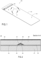
- the pressure-sensitive exercise mat as a whole is illustrated schematically in Fig. 1 .
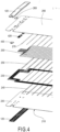
- the mat 100 has an elongate elastic body 110 with a flexible upper surface 112 for performing the exercises. Adjacent to one end of the mat 100, the mat is equipped with a case 120 for holding a battery 410, a signal processing unit 420 and a communication interface unit 430, like an USB port, a Bluetooth port, etc., as shown in Fig. 4 , that are configured to provide various smart functions for the mat 100.
- the case 120 is mounted on the upper and lower surfaces of the mat 100 and defines an internal space volume for accommodating the battery the signal processing unit and the communication interface unit.
- FIG. 2 and 3 a preferred embodiment of the mat 100 is illustrated in a cross-sectional view along the line A-A and B-B shown in Fig. 1 , respectively. Furthermore, Fig. 4 illustrates the subsequent layers of the mat 100 in an exploded view.
- the pressure-sensitive exercise mat 100 is formed of multiple layers arranged one over the other. Some layers are formed as solid layers extend to the entire length and width of the mat 100, while other layers consist of a plurality of separate units arranged according to a predetermined pattern, for example in a matrix pattern.
- the lowermost layer is a first mat layer 210 made of a rubber-based material.
- the first mat layer 210 is in contact with the ground and therefore its material may be specifically designed to have a high coefficient of adhesive friction.
- the material of the first mat layer 210 is a combined polyurethane and rubber foam.
- the mat 100 comprises an elastic hot-melt glue layer 220, the thickness of which is typically 0,05 to 0,25 mm.
- the glue layer 220 extends over the entire surface of the underlying first mat layer 210.
- the glue layer 220 for example,
- a first conductor layer 230 is arranged on the hot-melt glue layer 220.
- the first conductor layer 231 is formed of a plurality of electrically conducting wires, each wire extending in a first direction with a predetermined distance from each other, which, in the present case, is a direction parallel to the shorter edge of the rectangular mat 100. It is particularly preferred that the wires of the first conductor layer 230 extend along substantially the entire width of the mat 100.
- the material of the wires may be selected from the group of copper, silver or any other material with good electrically conductive properties.
- the linear density of the wires of the first conductor layer 230 typically ranges from 117x2 dtex to 235x2 dtex.
- a first electrode layer 240 is arranged over the first conductive layer 230.
- the first electrode layer 240 is formed of a plurality of separate first metal plates that are arranged according to a predetermined pattern, preferably a matrix pattern. Each first metal plate is electrically connected to a wire of the first conductor layer 230 and besides the respective wire, as shown in Fig. 3 , it is also attached to the hot-melt glue layer 220 which fixes the metal plate relative to the first mat layer 210.
- the metal plates of the first electrode layer 240 may have a material selected from the group of copper, silver or any material with good electrically conductive properties.
- the area of the metal plates of the first electrode layer 240 typically ranges 1 to 2 cm 2 .
- the metal plates of the first electrode layer 240 are covered by a plurality of separate pressure-gauge foil pieces that form a pressure-sensitive layer 250.
- the foil pieces extend beyond the underlying metal pieces at least in one direction.
- each foil piece is attached to said hot-melt glue layer 220, which thereby fixes the foil pieces relative to the metal plates.
- the conductive material of the pressure-sensitive layer 250 is a pressure-sensitive foil (squeezing it will reduce the resistance), for example, the Linqstat ® foil of the company Caplinq.
- the area of the foil pieces preferably ranges 1 to 2,5 cm 2 .
- a second conductor layer 260 is arranged over the pressure-sensitive layer 250, wherein the second conductor layer 260 is formed of a plurality of electrically conducting metal wires, each wire extending in a second direction transversal to said first direction, i.e. in the longitudinal direction of the mat 100, in the present embodiment.
- Each metal wire of the second conductor layer 260 is in contact with an associated pressure-gauge foil piece of the underlying pressure-sensitive layer 250 and is also attached to said hot-melt glue layer 220 besides the foil pieces as best shown in Fig. 3 .
- the wires of the second conductor layer 260 may be made of the same material and may have the same dimensions as the wires of the first conductor layer 230.
- a second electrode layer 270 is arranged over the second conductive layer, this layer being formed of a plurality of separate second metal plates that are arranged according to said predetermined pattern, in alignment with the first metal plates of the first electrode layer 240.
- Each second metal plate is electrically connected to a wire of the second conductor layer 260 and is also attached to said hot-melt glue layer 220 besides the area of the pressure-gauge foil pieces, as it can be clearly seen in Fig. 2 .
- the second metal plates extend beyond the underlying pressure-gauge foil pieces at least in one direction.
- the hot-melt glue layer 220 also fixes the second metal plates.
- the second metal plates of the second electrode layer 270 may be made of the same material as the first metal plates of the first electrode layer 240.
- a second mat layer 280 made of the same rubber-based material as that of the first mat layer 210 is arranged.
- the second mat layer 280 is attached to the hot-melt glue layer 220 along the surface areas that are not covered by the first and second wires, the first and second metal plates and the pressure-gauge foil pieces, so the first and second mat layers 210, 280 together form an elastic body of the mat 100.
- the second mat layer 280 is covered on its entire surface by a flexible layer, typically made of polyurethane foam, for making the use of the mat 100 convenient to the user while exercising on the mat 100.
- a flexible layer typically made of polyurethane foam
- the first and second conductor layers, the first and second electrode layers and the pressure-sensitive layer are all embedded in the hot-melt glue layer. Accordingly, in this embodiment, the glue layer is somewhat thicker than in the first embodiment, which allows for the pressure-sensitive foil pieces and the second metal plates to have smaller dimensions.
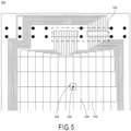
- Figure 5 illustrates an exemplary wiring scheme 500 of a preferred embodiment of the pressure sensitive exercise mat according to the invention.
- the first wires 510 of the first conductor layer run crosswise and the second wires 520 of the second conductor layer run lengthwise, thereby defining a mesh of wires, at the intersections 525 of which the pressure sensor units 526 are mounted, each being formed of a first and a second metal plate with a pressure-gauge foil piece therebetween.
- the first and second wires 510, 520 run into a signal processing unit 530 accommodated in the case adjacent to one end of the mat.
- the rectangular mesh-like wiring scheme shown in Fig. 5 has the advantage of allowing a matrix pattern for the pressure sensors along a substantial area of the mat, it is obvious for those ordinary skilled in the art that many other wiring scheme may be appropriate for providing a matrix pattern or other patterns of the pressure sensor units.
- the mat according to the present invention may be manufactured by the following process.
- the main steps of the manufacturing process are illustrated by the flow diagram of Fig. 6 .
- a soft rubber-based rectangular sheet is provided as a first mat layer.
- an elastic hot-melt glue layer is applied on the upper side of the first mat layer at ambient temperature (typically 20-25°C).
- a first (lower) conductor layer formed of a plurality of metal wires is superposed on the hot-melt glue layer by means of an appropriate wire manipulation tool, wherein the wires of this conductor layer run in a first direction, e.g. in a direction perpendicular to the longitudinal direction of the elongate mat.
- a plurality of metal plates are arranged along the wires of the first conductor layer at predetermined positions. These metal plates form a first (lower) electrode layer.
- the metal plates are arranged in a matrix pattern. The lower side of the metal plates are brought into contact with the hot-melt glue. The lower metal plates are in electrical contact with the underlying lower metal wires.
- a plurality of separate pressure-gauge foil pieces are arranged on the metal plates. These foil pieces from the pressure-sensitive layer.
- the foil pieces are dimensioned so that each of them slightly extends beyond the periphery of the associated metal plate at least in one direction. In this way the foil pieces are also brought into contact with the hot-melt glue layer.
- step 650 second (upper) conductor layer formed of a plurality of metal wires is laid, by means of said wire manipulation tool, over the underlying layers in a way that the wires of this upper conductor layer are also in contact with the hot-melt glue layer outside the areas covered by the lower metal plates and the pressure-gauge foil pieces.
- the wires of this upper conductor layer run in second first direction orthogonal to the first wiring direction, e.g. in parallel to the longitudinal direction of the elongate mat.
- step 660 a plurality of further metal plates are arranged over the second (upper) electrode layer at the positions where the lower metal plates are accommodated. These further metal plates form a second (upper) electrode layer.
- the upper metal plates are dimensioned so that they are also in contact with the hot-melt glue layer outside the areas covered by the lower metal plates, the pressure-gauge foil pieces and the upper metal wires.
- the upper metal plates are in electrical contact with the upper metal wires.
- the upper metal plates and the upper wires are electrically insulated from the lower metal plates and the lower metal wires by the pressure-gauge foil pieces.
- the lower and upper metal plates, as well the foil pieces may be moved using a vacuum griper tool.
- a second mat layer made of the same soft rubber-based material as used in the lower mat layer is arranged on the combined underlying layers so that it is brought into contact with a substantial area of the hot-melt glue layer.
- a soft polyurethan foam layer is adhered to the upper mat layer and then in step 690, the sandwich-like mat structure is subject to heat so that the glue inside become molten and adhere to the attached components of the above layers.
- the case holding specific electronic parts is attached to the mat in a way that a lower half case and upper half case is pressed against each other.
- the two halves of the case may be secured to each other by screws, glue, snap-fit joints, etc.
- the mat 100 has a built-in electronic circuitry within the case 120 that measures the pressure distribution over a matrix of the sensor units formed by the lower and upper metal plates of the first and second electrode layers 240, 270, respectively, and the pressure-gauge foil pieces of the pressure sensitive layer 250.
- the pressure values measured by the sensor units may be generated on the basis of changes in the electrical resistance of the foil pieces when the user applies pressure on the mat 100.
- the signal processing unit 420 or within the case 120, the pressure values are converted into 8-bit digital signals for each sensor unit, and hence, the pressure values may range between 0 and 255.
- the signal processing unit 420 may be configured to generate a pressure map for all sensor units in a matrix pattern. This pressure map may be generated in real time and may be forwarded to a remote processing unit for gaining specific information on the quality or other features of the exercise performed by the person using the mat 100.
- the pressure measurement may be carried out at a predetermined sampling frequency which may be defined on the basis of the data link bandwidth and the data aggregation (averaging) capabilities of the communication interface unit 430 of the mat 100. Small amount of measurement data may be buffered in a built-in memory of the mat's electronics within the case 120.
- the pressure measurement data may be transferred wirelessly, e.g. via Bluetooth, to any external device capable of connecting to the communication interface unit 430 of the mat 100 and receiving the measurement data.
- the external device may be a portable smart device, such as a mobile phone or a tablet, which runs a specific software application for processing the measurement data and visualizing the results of the data processing.
- the portable smart device may also be connected to a remote server computer or a cloud data processing and storage platform, which may be configured to provide further data processing and data storage functions in addition to those carried out by the local portable smart device.
- the information generated by the external computing resources may be used to give feedback to the user of the mat 100, and, in case of the local data collection and processing, for testing and development purposes.
- the dedicated software application of the connected portable smart device may be used for presenting the resulted information for the user either through visual presentation on the display of the smart device or by any other way, e.g. via audio signals, vibration, light indication, etc.
- the information presented for the user may give certain feedback on the quality, the intensity and/or the general nature of any practice executed by the user on the mat 100.
- the software application may be configured to track personal development of the user and to motivate the user for further practice.
Landscapes
- Health & Medical Sciences (AREA)
- Life Sciences & Earth Sciences (AREA)
- Biophysics (AREA)
- Orthopedic Medicine & Surgery (AREA)
- General Health & Medical Sciences (AREA)
- Physical Education & Sports Medicine (AREA)
- Force Measurement Appropriate To Specific Purposes (AREA)
Priority Applications (1)
| Application Number | Priority Date | Filing Date | Title |
|---|---|---|---|
| EP22462009.6A EP4360718A1 (fr) | 2022-10-27 | 2022-10-27 | Tapis d'exercice sensible à la pression |
Applications Claiming Priority (1)
| Application Number | Priority Date | Filing Date | Title |
|---|---|---|---|
| EP22462009.6A EP4360718A1 (fr) | 2022-10-27 | 2022-10-27 | Tapis d'exercice sensible à la pression |
Publications (1)
| Publication Number | Publication Date |
|---|---|
| EP4360718A1 true EP4360718A1 (fr) | 2024-05-01 |
Family
ID=84361415
Family Applications (1)
| Application Number | Title | Priority Date | Filing Date |
|---|---|---|---|
| EP22462009.6A Withdrawn EP4360718A1 (fr) | 2022-10-27 | 2022-10-27 | Tapis d'exercice sensible à la pression |
Country Status (1)
| Country | Link |
|---|---|
| EP (1) | EP4360718A1 (fr) |
Cited By (1)
| Publication number | Priority date | Publication date | Assignee | Title |
|---|---|---|---|---|
| GB2633193A (en) * | 2023-08-29 | 2025-03-05 | Stiltz Ltd | Elevator plate assembly |
Citations (7)
| Publication number | Priority date | Publication date | Assignee | Title |
|---|---|---|---|---|
| US20150364059A1 (en) | 2014-06-16 | 2015-12-17 | Steven A. Marks | Interactive exercise mat |
| EP3047794A1 (fr) | 2013-09-16 | 2016-07-27 | Sensing Tex, S.L. | Capteur textile piézorésistif et système de détection du rythme cardiaque et/ou respiratoire |
| US20170080279A1 (en) * | 2015-03-03 | 2017-03-23 | Andrew Arredondo | Integrated exercise mat system |
| US20200254299A1 (en) | 2019-02-11 | 2020-08-13 | Wellnesys Inc. | System and non-intrusive method for exercise posture detection |
| US20210068245A1 (en) | 2018-02-22 | 2021-03-04 | Wellnesys Inc. | Flexible substrate and a method thereof |
| JP2021037168A (ja) | 2019-09-04 | 2021-03-11 | ヨクト株式会社 | 運動解析システム、運動解析プログラム、及び運動解析方法 |
| CN216125132U (zh) * | 2021-10-22 | 2022-03-25 | 武汉飞帛丝科技有限公司 | 智能瑜伽垫 |
-
2022
- 2022-10-27 EP EP22462009.6A patent/EP4360718A1/fr not_active Withdrawn
Patent Citations (7)
| Publication number | Priority date | Publication date | Assignee | Title |
|---|---|---|---|---|
| EP3047794A1 (fr) | 2013-09-16 | 2016-07-27 | Sensing Tex, S.L. | Capteur textile piézorésistif et système de détection du rythme cardiaque et/ou respiratoire |
| US20150364059A1 (en) | 2014-06-16 | 2015-12-17 | Steven A. Marks | Interactive exercise mat |
| US20170080279A1 (en) * | 2015-03-03 | 2017-03-23 | Andrew Arredondo | Integrated exercise mat system |
| US20210068245A1 (en) | 2018-02-22 | 2021-03-04 | Wellnesys Inc. | Flexible substrate and a method thereof |
| US20200254299A1 (en) | 2019-02-11 | 2020-08-13 | Wellnesys Inc. | System and non-intrusive method for exercise posture detection |
| JP2021037168A (ja) | 2019-09-04 | 2021-03-11 | ヨクト株式会社 | 運動解析システム、運動解析プログラム、及び運動解析方法 |
| CN216125132U (zh) * | 2021-10-22 | 2022-03-25 | 武汉飞帛丝科技有限公司 | 智能瑜伽垫 |
Cited By (1)
| Publication number | Priority date | Publication date | Assignee | Title |
|---|---|---|---|---|
| GB2633193A (en) * | 2023-08-29 | 2025-03-05 | Stiltz Ltd | Elevator plate assembly |
Similar Documents
| Publication | Publication Date | Title |
|---|---|---|
| US8127623B2 (en) | Capacitive tactile tile sensor | |
| US20160296135A1 (en) | Electrical impedance tomography device | |
| JP7632908B2 (ja) | 変形可能センサ | |
| US10048141B2 (en) | Pressure sensing element and pressure sensor | |
| EP3246685B1 (fr) | Élément sensible à la pression, capteur de pression, et procédé de fabrication d'un élément sensible à la pression | |
| CA1272393A (fr) | Senseur tactile electrographique determinant la coordonnee z | |
| JP5995362B2 (ja) | 分布量センサおよび分布量計測システム | |
| EP2833111A1 (fr) | Capteur capacitif | |
| JP2012521550A (ja) | センサ | |
| JP2008256470A (ja) | 圧力分布センサシステム | |
| WO2015175317A1 (fr) | Capteurs piézorésistifs et applications | |
| US20200292399A1 (en) | Sensor systems | |
| US20200225099A1 (en) | A dual use strain sensor | |
| CN114343613B (zh) | 一种基于足底压力的运动检测装置 | |
| CN113008418A (zh) | 一种压阻型柔性触觉传感器 | |
| CN111256880A (zh) | 压力传感织物及压力检测系统 | |
| CN117258211B (zh) | 智能垫与智能垫的多点检测方法 | |
| US11057990B2 (en) | Flexible substrate and a method thereof | |
| US12546672B2 (en) | Apparatus for determining shear forces in regard to a pressure imaging array, single point sensor for shear forces, and method | |
| CN218349613U (zh) | 体重垫 | |
| CN210697628U (zh) | 一种电极式贴片、检测设备和检测系统 | |
| CN202681916U (zh) | 一种用于人体成分测试仪的检测设备 | |
| CN218822148U (zh) | 一种应变式传感器及电子设备 | |
| CN116007488B (en) | Distributed flexible sensor, distributed sensing system and electronic equipment | |
| US20250244184A1 (en) | Smart fabric impact sensors |
Legal Events
| Date | Code | Title | Description |
|---|---|---|---|
| PUAI | Public reference made under article 153(3) epc to a published international application that has entered the european phase |
Free format text: ORIGINAL CODE: 0009012 |
|
| STAA | Information on the status of an ep patent application or granted ep patent |
Free format text: STATUS: THE APPLICATION HAS BEEN PUBLISHED |
|
| AK | Designated contracting states |
Kind code of ref document: A1 Designated state(s): AL AT BE BG CH CY CZ DE DK EE ES FI FR GB GR HR HU IE IS IT LI LT LU LV MC ME MK MT NL NO PL PT RO RS SE SI SK SM TR |
|
| STAA | Information on the status of an ep patent application or granted ep patent |
Free format text: STATUS: THE APPLICATION IS DEEMED TO BE WITHDRAWN |
|
| 18D | Application deemed to be withdrawn |
Effective date: 20241105 |