EP4360772A1 - Verfahren und system zum stapeln von blechteilen - Google Patents
Verfahren und system zum stapeln von blechteilen Download PDFInfo
- Publication number
- EP4360772A1 EP4360772A1 EP22383041.5A EP22383041A EP4360772A1 EP 4360772 A1 EP4360772 A1 EP 4360772A1 EP 22383041 A EP22383041 A EP 22383041A EP 4360772 A1 EP4360772 A1 EP 4360772A1
- Authority
- EP
- European Patent Office
- Prior art keywords
- sheet metal
- movable frame
- axis
- stack
- positioning
- Prior art date
- Legal status (The legal status is an assumption and is not a legal conclusion. Google has not performed a legal analysis and makes no representation as to the accuracy of the status listed.)
- Pending
Links
Images




Classifications
-
- B—PERFORMING OPERATIONS; TRANSPORTING
- B21—MECHANICAL METAL-WORKING WITHOUT ESSENTIALLY REMOVING MATERIAL; PUNCHING METAL
- B21D—WORKING OR PROCESSING OF SHEET METAL OR METAL TUBES, RODS OR PROFILES WITHOUT ESSENTIALLY REMOVING MATERIAL; PUNCHING METAL
- B21D43/00—Feeding, positioning or storing devices combined with, or arranged in, or specially adapted for use in connection with, apparatus for working or processing sheet metal, metal tubes or metal profiles; Associations therewith of cutting devices
- B21D43/20—Storage arrangements; Piling or unpiling
- B21D43/22—Devices for piling sheets
-
- B—PERFORMING OPERATIONS; TRANSPORTING
- B21—MECHANICAL METAL-WORKING WITHOUT ESSENTIALLY REMOVING MATERIAL; PUNCHING METAL
- B21D—WORKING OR PROCESSING OF SHEET METAL OR METAL TUBES, RODS OR PROFILES WITHOUT ESSENTIALLY REMOVING MATERIAL; PUNCHING METAL
- B21D43/00—Feeding, positioning or storing devices combined with, or arranged in, or specially adapted for use in connection with, apparatus for working or processing sheet metal, metal tubes or metal profiles; Associations therewith of cutting devices
- B21D43/003—Positioning devices
-
- B—PERFORMING OPERATIONS; TRANSPORTING
- B21—MECHANICAL METAL-WORKING WITHOUT ESSENTIALLY REMOVING MATERIAL; PUNCHING METAL
- B21D—WORKING OR PROCESSING OF SHEET METAL OR METAL TUBES, RODS OR PROFILES WITHOUT ESSENTIALLY REMOVING MATERIAL; PUNCHING METAL
- B21D43/00—Feeding, positioning or storing devices combined with, or arranged in, or specially adapted for use in connection with, apparatus for working or processing sheet metal, metal tubes or metal profiles; Associations therewith of cutting devices
- B21D43/02—Advancing work in relation to the stroke of the die or tool
- B21D43/04—Advancing work in relation to the stroke of the die or tool by means in mechanical engagement with the work
- B21D43/10—Advancing work in relation to the stroke of the die or tool by means in mechanical engagement with the work by grippers
- B21D43/105—Manipulators, i.e. mechanical arms carrying a gripper element having several degrees of freedom
-
- B—PERFORMING OPERATIONS; TRANSPORTING
- B21—MECHANICAL METAL-WORKING WITHOUT ESSENTIALLY REMOVING MATERIAL; PUNCHING METAL
- B21D—WORKING OR PROCESSING OF SHEET METAL OR METAL TUBES, RODS OR PROFILES WITHOUT ESSENTIALLY REMOVING MATERIAL; PUNCHING METAL
- B21D43/00—Feeding, positioning or storing devices combined with, or arranged in, or specially adapted for use in connection with, apparatus for working or processing sheet metal, metal tubes or metal profiles; Associations therewith of cutting devices
- B21D43/02—Advancing work in relation to the stroke of the die or tool
- B21D43/18—Advancing work in relation to the stroke of the die or tool by means in pneumatic or magnetic engagement with the work
-
- B—PERFORMING OPERATIONS; TRANSPORTING
- B25—HAND TOOLS; PORTABLE POWER-DRIVEN TOOLS; MANIPULATORS
- B25J—MANIPULATORS; CHAMBERS PROVIDED WITH MANIPULATION DEVICES
- B25J9/00—Program-controlled manipulators
- B25J9/16—Program controls
- B25J9/1679—Program controls characterised by the tasks executed
-
- B—PERFORMING OPERATIONS; TRANSPORTING
- B65—CONVEYING; PACKING; STORING; HANDLING THIN OR FILAMENTARY MATERIAL
- B65G—TRANSPORT OR STORAGE DEVICES, e.g. CONVEYORS FOR LOADING OR TIPPING, SHOP CONVEYOR SYSTEMS OR PNEUMATIC TUBE CONVEYORS
- B65G60/00—Simultaneously or alternatively stacking and de-stacking of articles
-
- G—PHYSICS
- G05—CONTROLLING; REGULATING
- G05B—CONTROL OR REGULATING SYSTEMS IN GENERAL; FUNCTIONAL ELEMENTS OF SUCH SYSTEMS; MONITORING OR TESTING ARRANGEMENTS FOR SUCH SYSTEMS OR ELEMENTS
- G05B19/00—Program-control systems
- G05B19/02—Program-control systems electric
- G05B19/418—Total factory control, i.e. centrally controlling a plurality of machines, e.g. direct or distributed numerical control [DNC], flexible manufacturing systems [FMS], integrated manufacturing systems [IMS] or computer integrated manufacturing [CIM]
- G05B19/41815—Total factory control, i.e. centrally controlling a plurality of machines, e.g. direct or distributed numerical control [DNC], flexible manufacturing systems [FMS], integrated manufacturing systems [IMS] or computer integrated manufacturing [CIM] characterised by the cooperation between machine tools, manipulators and conveyor or other workpiece supply system, workcell
-
- G—PHYSICS
- G05—CONTROLLING; REGULATING
- G05B—CONTROL OR REGULATING SYSTEMS IN GENERAL; FUNCTIONAL ELEMENTS OF SUCH SYSTEMS; MONITORING OR TESTING ARRANGEMENTS FOR SUCH SYSTEMS OR ELEMENTS
- G05B2219/00—Program-control systems
- G05B2219/30—Nc systems
- G05B2219/40—Robotics, robotics mapping to robotics vision
- G05B2219/40006—Placing, palletize, un palletize, paper roll placing, box stacking
-
- G—PHYSICS
- G05—CONTROLLING; REGULATING
- G05B—CONTROL OR REGULATING SYSTEMS IN GENERAL; FUNCTIONAL ELEMENTS OF SUCH SYSTEMS; MONITORING OR TESTING ARRANGEMENTS FOR SUCH SYSTEMS OR ELEMENTS
- G05B2219/00—Program-control systems
- G05B2219/30—Nc systems
- G05B2219/40—Robotics, robotics mapping to robotics vision
- G05B2219/40066—Stack and align identical layers, laminates, electronic substrate layers
-
- G—PHYSICS
- G05—CONTROLLING; REGULATING
- G05B—CONTROL OR REGULATING SYSTEMS IN GENERAL; FUNCTIONAL ELEMENTS OF SUCH SYSTEMS; MONITORING OR TESTING ARRANGEMENTS FOR SUCH SYSTEMS OR ELEMENTS
- G05B2219/00—Program-control systems
- G05B2219/30—Nc systems
- G05B2219/40—Robotics, robotics mapping to robotics vision
- G05B2219/40421—Motion planning for manipulator handling sheet metal profiles
-
- G—PHYSICS
- G05—CONTROLLING; REGULATING
- G05B—CONTROL OR REGULATING SYSTEMS IN GENERAL; FUNCTIONAL ELEMENTS OF SUCH SYSTEMS; MONITORING OR TESTING ARRANGEMENTS FOR SUCH SYSTEMS OR ELEMENTS
- G05B2219/00—Program-control systems
- G05B2219/30—Nc systems
- G05B2219/45—Nc applications
- G05B2219/45234—Thin flat workpiece, sheet metal machining
Definitions
- This invention is related to the field of handling and conveying flat components, preferably sheet metal parts such as metal plates, metal panels or metal sheets, and more particularly to the unstacking and stacking of said sheet metal parts.
- Machine tools such as bending presses, laser cutting machines, drilling machines, etc., require the selective feeding of individual workpieces, with particular attention being paid to the correct alignment of the workpieces in relation to the machine tool in which they are to be processed and its particular reference system.
- the workpiece is conveyed to the machine tool, for example, by an automatic feeding device, but the correct alignment of the workpiece in relation to the machine tool must then be carried out by an operator. Thus, in such case, the correct alignment of the workpiece will rely on the user's experience.
- measures are required to ensure the correct alignment of the workpiece in relation to the machine tool. Since the workpieces are delivered to the machine tool on a transport pallet from an upstream processing step, for example, it is usually ensured that the workpieces are correctly arranged on the pallet in their basic alignment, but there may be slight deviations in the detailed alignment. Thus, before inserting the workpiece into the machine tool, the deviation from a target position must be corrected in any case in order to have the pieces correctly processed.
- Sheet metal parts in particular, metal sheets, panels and plates which, due to their characteristics (their delicate nature which makes them prone to suffer deformations and their large size) require specific customized solutions offering space optimization, handling precision and efficient management with no compromise on safety.
- Sheet metal parts that arrive to the machining industry directly from the sheet metal part manufacturers are normally stored in stacks.
- the sheet metal parts in the stack are generally not perfectly aligned, existing some deviations between them.
- Some solutions have tried to align said stacks by using presses that exert forces on the side faces of the stack.
- some substances such as water, dust or other organic or inorganic compounds could have been deposited on the surfaces of the sheet metal parts generating high cohesive and adhesive forces between them.
- vacuum could be created between adjacent sheet metal parts adhering them to each other. Then, the side forces applied by these presses may bend and deform some of the sheet metal parts in the stack.
- these stacks may comprise dozens of sheet metal parts that, for productive or organization reasons, may have to be unstacked to be subsequently stacked forming stacks on pallets with a different number of sheet metal parts.
- Sheet metal parts on pallets as they are supplied by providers, present misalignments between them such that, before said sheet metal parts are to be stored in an automatic warehouse at the industrial facility it is convenient to restack them adequately and precisely on the pallet of the automatic warehouse without these misalignments. In this way, when these sheet metal parts arrive to the systems that are going to machine them, they are aligned with the required precision. Additionally, the storage of the pallet from the supplier, that would occupy some space in the automatic warehouse, is avoided.
- the unstacking and subsequent stacking steps are normally carried out in the facility in which they are going to be processed and right before they are to be stored and/or processed in the corresponding machine tools. It is important that these newly stacked sheet metal parts are correctly aligned in order to avoid having to realign them once they are in the machine tool and also in order to avoid that these misalignments may provoke defects in the machined pieces.
- stop device in which the workpieces are placed to ensure their correct alignment.
- these solutions have the disadvantages that the stop device has to be adapted each time the type of workpiece is changed, which usually means more work, and that it requires at least one additional work step and possibly necessitates a reorientation of the manipulation device.
- stops can also damage the machine in which they are installed due to the impact of the sheet metal parts against the stops.
- the present invention discloses a method and a system for stacking sheet metal parts that ensures a correct alignment of the stacked sheet metal parts in the stack.
- a first object of the invention is a method for stacking sheet metal parts. The method comprises the steps of:
- the method provides the movable frame with at least three positioning sensors (X c1 ,X c2 ,Y c ), wherein two of the sensors (X c1 , X c2 ) are located on a first edge of the movable frame in correspondence with the X-axis and a third sensor (Y c ) is located on a second edge of the movable frame in correspondence with Y-axis.
- the first edge of the movable frame is the edge that is parallel to the line defined by the positioning sensors (X b1 , X b2 ) of the fixed frame used to position the sheet metal parts parallel to X-axis, and that is located closer to the storing area when the movable frame is inside the reception area while the second edge is the edge that is perpendicular to the first edge.
- the movable frame will be preferably rectangular or quadrangular shaped.
- the method comprises determining the position of the first stack in the reception area by using the three positioning sensors (X c1 ,X c2 ,Y c ) of the movable frame and aligning the movable frame with the first stack based on the determined position.
- the position of the first stack can be provided to the controller by a user, it will be preferably and automatically carried out by the method for each sheet metal part of the stack due to the existence of misalignments between the sheet metal parts in the first stack.
- the method may further calculate the angular deviation of the first stack relative to the X-axis.
- the controller with movable frame being aligned with X-axis and Y-axis, may calculate the angle " ⁇ " (angular deviation of the first stack) in a similar way to how the angle "a” is calculated but using the positing sensors (X c1 ,X c2 ,Y c ) of the movable frame instead of the positioning sensors (X b1 ,X b2 ,Y b ) of the fixed frame.
- angle " ⁇ " as the arctan D o D c , wherein 'D o ' is a distance travelled by the movable frame between an instant in which one of the first and the second positioning sensors (X c1 ,X c2 ) of the movable frame detect an edge of the top sheet metal part of the first stack and an instant in which the other one of the first and the second positioning sensors (X c1 ,X c2 ) detect the same edge of the sheet metal part.
- 'D c ' is the distance between the first and second positioning sensors (X c1 ,X c2 ) of the movable frame.
- Angle " ⁇ " determines the angular offset of the sheet metal around Z-axis.
- the movable frame is rotated the angle " ⁇ " every time a sheet metal part of the first stack is to be gripped. Since the sheet metal parts of the same stack present small misalignments between them, this calculation only needs to be carried out for the top sheet metal part of the stack.
- the controller is provided with the dimensions of the sheet metal parts of the first stack. Then, the movable frame moves relative to the top sheet metal part of the first stack until the sensors (X c1 ,X c2 ) located in the first edge of the movable frame are located in correspondence with a first edge of the top sheet metal part and the sensor (Y c ) located on a second edge of the movable frame is located in correspondence with a second edge of the top sheet metal part.
- the controller that knows the location of its three sensors (X c1 ,X c2 ,Y c ), and the distances among them and the dimensions of the sheet metal part, determines the distance between the geometrical centre of the movable frame and the geometrical centre of the sheet metal part, in particular, the distance in the X-axis and in the Y-axis and moves the movable frame relative to the sheet metal part until both geometrical centres are coincident.
- the movable frame can grip the sheet metal part.
- the method comprises providing a support element, for example a pallet of an automatic warehouse, on which the second stack of sheet metal parts is to be deposited on the storing area.
- a support element for example a pallet of an automatic warehouse
- This support element can be provided manually by a user or it can be provided by an automatic mechanism, for example an automatic pallet dispenser or a stacker crane.
- the controller determines the position of the support element in the storing area using the three positioning sensors (X c1 ,X c2 ,Y c ) of the movable frame.
- the controller is provided with the dimensions of the support element and the movable frame is moved relative to the support element until the two sensors (X c1 ,X c2 ) in the first edge of the movable frame are located in correspondence with a first edge of the support element and the third sensor (Y c ) of the movable frame is located in correspondence with a second edge of the support element.
- the controller that knows the location of three sensors (X c1 ,X c2 ,Y c ) of the movable frame and the distances among them and the dimensions of the support element, calculates a distance between a geometrical centre of the movable frame and the geometrical centre of the support element in the X-axis and in the Y-axis and calculates the distance between an edge of the support element and the positioning sensors (X b1 ,X b2 ,Y b ) of the fixed frame using the two sensors (X c1 ,X c2 ) in the first edge of the movable frame.
- the method comprises measuring, by a height measurement sensor (Z h ) located in the movable frame, a distance in Z-axis between the movable frame and the support element or the top sheet metal part of the second stack. This measurement can be carried out after the position of the support element is determined and every time a sheet metal part is deposited on the second stack is to be gripped. With this information and knowing the thickness of the sheet metal parts, the controller knows how much the movable frame is to be lowered for depositing the next sheet metal part on the second stack.
- Z h height measurement sensor
- the method comprises measuring, by the height measurement sensor (Z h ) located in the movable frame, a distance in Z-axis between the movable frame and the top sheet metal part of the first stack. With this information, the controller knows how much the movable frame is to be lowered for gripping the top sheet metal part of the first stack so it can instruct the XYZ positioning system to lower the movable frame the measured height until the vacuum cups of the vacuum gripper contact the upper surface of the top sheet metal part.
- the sheet metal parts are selected from a group comprising metal plates, metal panels, metal sheets and any combination thereof. These sheet metal parts may have any dimension, provided that they are equal or bigger than the dimensions of the movable frame.
- the sheet metal parts may be 3000x1500x3mm or 2500x1250x2mm.
- a second object of the invention is a machine for stacking sheet metal parts, that comprises a fixed frame having a reception area configured to receive a first stack of sheet metal parts, a storing area configured to store a second stack of sheet metal parts and at least three positioning sensors (X b1 ,X b2 ,Y b ) configured to detect the sheet metal parts.
- These positioning sensors can detect the presence of the sheet metal parts and they may be Potentiometric Position Sensors (resistance-based), Inductive Position Sensors, Eddy Current-Based Position Sensors, Capacitive Position Sensors, Magnetostrictive Position Sensors, Hall Effect-Based Magnetic Position Sensors, Fiber-Optic Position Sensors, Optical Position Sensors, Ultrasonic Position Sensors and any combination thereof.
- they will be optical position sensors such as transmissive optical encoders, reflective optical encoders or interferential optical encoders.
- the machine further comprises a movable frame comprising a vacuum gripper configured to grip the sheet metal parts.
- the vacuum gripper may comprise one or more suction or vacuum cups attached to the movable frame that use negative air pressure to adhere to the surfaces of the sheet metal parts, creating a partial vacuum on their upper surface. These vacuum cups are positioned on the movable frame on the same plane and, generally, equally spaced.
- the machine also comprises a XYZ positioning system configured to move the movable frame relative to the fixed frame in the X-axis, Y-axis and Z-axis, a rotary joint located between the movable frame and the XYZ positioning system that is configured to rotate the movable frame around Z-axis and a controller configured to manage the positioning sensors, the vacuum gripper, the XYZ positioning system and the rotary joint and to carry out the steps of the method for stacking sheet metal parts a previously described.
- the controller comprises the hardware and software to manage the positioning sensors, the vacuum gripper, the XYZ positioning system and the rotary joint and to carry out the steps of the method for stacking sheet metal parts a previously described.
- This controller may include, for example, one processor or multiple processors included in a single computing device or distributed across multiple computing devices.
- the controller will be Computer Numerical Control (CNC) machine.
- the control unit may be integrated into the machine or may be an external device connected to the machine from which the machine is remotely controlled.
- the vacuum gripper may be any device comprising one or more suction or vacuum cups, also known as suckers, that use negative fluid pressure of air to adhere to the surfaces, creating a partial vacuum.
- the vacuum gripper will also comprise a vacuum generator to generate the vacuum and a plurality of pipes, hoses and/or duct to connect the vacuum generator with the different vacuum cups. While the vacuum cups will be attached to the movable frame, preferably equally spaced, the vacuum generator, e.g., a compressor, will be preferably attached to the fixed frame.
- the movable frame is mounted on a portal-like guiding structure movable in the Y-axis direction.
- the movable frame comprises a height sensor (Z h ) configured to measure a distance between the movable frame and the fixed frame in the Z-axis. More particularly, the height sensor (Z h ) is configured to measure a distance between the movable frame and the top sheet metal part of the first stack, the top sheet metal part of the second stack and the support element.
- the movable frame comprises at least three positioning sensors (X c1 ,X c2 ,Y c ), wherein two of these sensors (X c1 ,X c2 ) are located on a first edge of the movable frame in correspondence with the X-axis and the third sensor (Y c ) is located on a second edge of the movable chassis in correspondence with Y-axis.
- These three positioning sensors (X c1 ,X c2 ,Y c ) are configured to measure at least one of the relative position between the movable frame and the sheet metal parts on the reception area and the relative position of the movable frame and a support element on the storing area of the fixed frame.
- the system comprises an intermediate beam attached to the fixed frame so as to separate the reception area from the storing area, wherein the three positioning sensors (X b1 ,X b2 ,Y b ), are mounted on the intermediate beam.
- these three positioning sensors (X b1 ,X b2 ,Y b ) may be mounted in any other part of the fixed frame.
- the solution herein disclosed provides an automated solution for stacking sheet metal parts that ensures a correct and identical alignment of all the stacked sheet metal parts so they can be inserted from a ready position into the machine tool for post processing operations. Besides, this solution presents a high flexibility since it can be used with sheet metal parts of very different dimensions by only feeding the controller with the dimensions of the sheet metal parts to be unstacked/stacked.
- Fig. 1 shows a flow diagram of the method (1) for stacking sheet metal parts, according to a particular embodiment of the invention.
- a fixed frame having a reception area that is to receive a first stack of sheet metal parts to be unstacked and a storing area that is to store a second stack made of the same sheet metal parts.
- the reception area and the storing area may have different sizes although preferably they may be similar in size.
- the reception area and the storing area can be separated by interposition of an intermediate beam which is attached to the fixed frame.
- the intermediate beam is provided with a first positioning sensor (X b1 ) and a second positioning sensor (X b2 ) that are used to position the sheet metal parts relative to the X-axis and a third positioning sensor (Y b ) that is used to position the sheet metal parts relative to Y-axis.
- a movable frame comprising a vacuum gripper configured to grip the sheet metal parts.
- the movable frame is coupled to the fixed frame by interposition of a XYZ positioning system configured to move the movable frame relative to the fixed frame along X-axis, Y-axis and Z-axis, and a rotary joint configured to rotate the movable frame around Z-axis.
- the top metal sheet of the first stack is gripped by suction with the vacuum gripper.
- the XYZ positioning system and the rotary joint will move the movable frame to position the vacuum cups of the vacuum gripper on the upper surface of the top metal sheet.
- suction is generated through the vacuum cups to grip the top metal sheet.
- the XYZ positioning system will lift the movable frame together with the top metal sheet.
- the movable frame is moved by the XYZ positioning system towards the storing area in the Y-axis direction until the first and second positioning sensors (X b1 ,X b2 ) have detected the metal sheet.
- the rotary junction rotates the movable frame the angle "a" around Z-axis so as to position the metal sheet parallel to the X-axis.
- the edge of the metal sheet closer to the intermediate beam is positioned parallel to the X-axis and thus, to the intermediate beam itself.
- the controller calculates a distance 'd 1 ' in Y-axis as a difference between a predefined position for stacking the metal sheets on the storing area and 'C s '.
- This distance 'd 1 ' corresponds to the distance in the Y-axis that the movable frame has to be moved relative to the fixed frame to position the metal sheet in correspondence with the Y-coordinate in which is to the stacked.
- the movable frame is moved by the XYZ positioning system in the X-axis direction until the third positioning sensor (Y b ) detects the metal sheet.
- the movable frame is moved by the XYZ positioning in the Y-axis direction and towards the storing area the distance 'd 1 ' and in the X-axis direction a distance 'd 2 ' corresponding to the difference between the position of the third sensor (Y b ) and the predefined position for stacking the sheet metal parts on the storing area.
- This distance 'd2' corresponds to the distance in the X-axis that the movable frame has to be moved relative to the fixed frame to position the metal sheet in correspondence with the X-coordinate in which is to the stacked.
- the metal sheet is deposited by the XYZ positioning system in the predetermined position forming the second stack. Once it has been deposited, the vacuum gripper will release the metal sheet and the movable frame will come back to the reception area to grip the next metal sheet from the first stack.
- Figure 2 shows a schematic plan view of the machine (20) for stacking sheet metal parts, according to a particular embodiment of the invention. It should be understood that the machine (20) may include additional components and that some of the components described herein may be removed and/or modified without departing from a scope of the machine (20). Additionally, implementation of the example machine (20) is not limited to such example as shown in Figure 2 .
- the machine (20) is formed by a fixed frame (21) which is located on the ground floor of the industrial facility and a movable frame (22) which is coupled to the fixed frame (21) by interposition of a portal-like guiding structure (28,29) movable in the Y-axis direction.
- This portal-like guiding structure (28,29) is composed by a U-shaped arm (28) with wheels (29) located in its free ends. These wheels (29) are actuated by servomotors or similar (not shown) and run along respective guides (30) located in the fixed frame (21) or in the floor of the facility.
- the U-shaped arm (28) comprises a mechanism, such as a guide or similar, (not shown) to guide the movable frame (22), which will be actuated by a motor, servomotor, etc., in the X-axis.
- the movable frame (22) is coupled to the U-shaped arm (28) by means of a rotary joint (26), actuated by a servomotor or similar, that allows the movable frame (22) to rotate around Z-axis.
- the movable frame (22) can be moved along the Z-axis by a servomotor or similar.
- the movement of the movable frame (22) in the 3 dimensions can be controlled by linear and rotary encoders and carried out by electric motors, rack and pinion mechanisms, gears, toothed belts, ball screws, etc.
- the fixed frame (21) has a reception area (23) where the individual metal sheets or a first stack of metal sheets is to be received and a storing area (24) where the metal sheets gripped by the movable frame (22) are placed and stacked in their right position.
- the reception area (23) and the storing area (24) are separated by an intermediate beam (25) attached to the fixed frame (21).
- the intermediate beam (25) has a first positioning sensor (Xb1) and a second positioning sensor (Xb2) to position the metal sheets relative to the X-axis, in particular, parallel to X-axis, and a third positioning sensor (Yb) to position the metal sheets relative to the Y-axis, in particular parallel to Y-axis.
- These sensors will be preferably optical sensors.
- the movable frame (22) comprises a vacuum gripper formed by a plurality of suction or vacuum cups (27), in this particular embodiment it comprises eight although it may comprise a different number, attached to the movable frame (22) that use negative air pressure to adhere to the surfaces of the metal sheets.
- These vacuum cups (27) are positioned on the movable frame (22) on the same plane and they are all fluidly connected to a vacuum system (not shown).
- the movable frame (22) also has two positioning sensors (X c1 ,X c2 ) located in correspondence with its front long edge and a third sensor (Y c ) located in correspondence with one of its short edge of the movable frame (22), that is perpendicular to the front long edge.
- These three sensors may be located in other locations of the movable frame (22) provided that they are parallel to X-axis and Y-axis, respectively.
- the three sensors (X c1 ,X c2 ,Y c ) will be preferably optical sensors.
- the different elements forming the machine (20) may be in a different number and may have a different shape, design and disposition.
- the movable frame may have a different design and the number of vacuum cups could be different.
- Figure 3 shows a plan view of the machine (20) of Figure 2 with the movable frame (22) positioned to determine the position of the metal sheet (32) to be gripped.
- the metal sheet (32) can be the top metal sheet of a stack of metal sheets stored on a pallet (31) that had been previously deposited on the reception area (23) by a user or by an automatic pallet feeding mechanism.
- the controller (33) instructs the XYZ positing system, that is to say to the motors that actuate the movable frame (22) to move in the X-axis and Y-axis, until the positioning sensors (X c1 ,X c2 ) detect the front long edge (the edge closer to the intermediate beam (25)) of the metal sheet (32) and the positioning sensor (Y c ) detects the side short edge (any of the two edges perpendicular to the front long edge) of the metal sheet (32).
- the controller (33) Since the controller (33) is provided with the dimensions of the metal sheet (32) and with a local reference system in which the origin of coordinates may be located in any point of the fixed frame (in the present embodiment said origin has been depicted in the left upper corner of the storing area (24)) and it knows the dimensions of the movable frame (22) and the distance between its three positioning sensors (X c1 ,X c2 ,Y c ) it is able to calculate the geometrical centres of the movable frame (22) and of the metal sheets (32). Then, the controller (33) can calculate the distances in the X-axis and Y-axis that the movable frame (22) has to be moved so both geometrical centres are coincident.
- the controller also calculates the angular deviation of the metal sheet (32) relative to the X-axis.
- the controller having the movable frame aligned with X-axis and Y-axis, calculates the angle " ⁇ " (angular deviation of the metal sheet (32)) as the arctan D o D c , wherein 'D o ' is a distance travelled by the movable frame (22) between an instant in which one of the first and the second positioning sensors (X c1 ,X c2 ) of the movable frame (22) detects the long edge of the metal sheet (32) and an instant in which the other one of the first and the second positioning sensors (X c1 ,X c2 ) detects the same long edge of the metal sheet (32).
- 'D c ' is the distance between the first and second positioning sensors (X c1 ,X c2 ).
- This angle " ⁇ " determines the angular offset of the metal sheet (32), and thus of the first stack since all the metal sheets that form it present only slight misalignments between them, around Z-axis. In this way, the movable frame (22) is rotated the angle " ⁇ " every time a metal sheet of the first stack is to be gripped. This calculation only needs to be carried out for the top metal sheet of the stack.
- Figure 4 shows a side view of the machine (20) of Figure 3 with the movable frame (22) measuring the distance in the Z-axis prior to gripping the metal sheet (32).
- the movable frame (22) comprises a fourth positioning sensor (Zh) to measure the distance (hi) between the movable frame (22) and the object located immediately below.
- the object is the top metal sheet (32) of the first stack (33). Knowing this distance, the controller (33) can instruct the XYZ positioning system to lower the movable frame (22) until the vacuum cups (27) contact the top metal sheet (32).
- This operation can be carried out every time a metal sheet has to be gripped by the vacuum gripper or only for the uppermost metal sheet of the stack and after that the controller can subtract the thickness of one metal sheet every time a metal sheet is gripped and transported to the storing area.
- the operation can be carried out every time a metal sheet has to be gripped and its outcome compared with the calculation carried by the controller as a redundant checking mechanism.
- the machine (20) will also measure this height for the pallet (not shown in this figure) located on the storing area (24). Again, this measurement can be carried out every time a metal sheet is deposited on the stack formed in the storing area (24) or it can be carried out for the empty pallet and then, the controller can just add the thickness of one metal sheet every time a metal sheet is deposited on said storing area (24). Alternatively, the operation can be carried out every time a metal sheet is deposited on the stack and this measure can be compared with the calculation carried by the controller as a redundant checking mechanism.
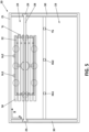
- Figure 5 shows a plan view of the machine (20) of Figure 2 with the movable frame (22) positioned to determine the position of the pallet (34), preferably a pallet from an automictic warehouse, on which the stack is to be formed on the storing area (24).
- the position of the pallet (34) in the storing area (24) is not provided by a user to the controller (33)
- the position of the pallet (34) is determined in the same way that the position of the metal sheet (32) to be gripped is determined in Figure 3 , by detecting the side edges of the pallet (34) with the three positioning sensors (X c1 ,X c2 ,Y c ) and using the local reference system of the machine (20).
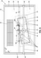
- Figure 6 shows a plan view of the machine of Figure 2 with the vacuum gripper griping a metal sheet.
- the movable frame (22) has been moved towards the storing area (24) in the Y-axis direction until the first and second positioning sensors (X b1 ,X b2 ) detect the metal sheet (32).
- the positing sensors (X c1 ,X c2 ,Y c ) of the movable frame (22) has been removed from this embodiment for clarity reasons.
- the controller (33) determines the distance 'C o ' travelled by the movable frame (22), and thus by the metal sheet (32), in the Y-axis direction between the instant in which the second positioning sensor (X b2 ) detects the metal sheet (32) and the instant in which the first positioning sensor (X b 1) detects the metal sheet (32).
- the controller also knows the distance 'C c ' between the first and second positioning sensors (X b 1,X b2 ). With this information, the controller calculates the angle "a" as the arctan C o C c . This angle "a” correspond to the angular misalignment (rotation) around Z-axis of the metal sheet (32).
- the controller (33) also determines the distance 'C r ' in the X-axis direction between the projection in the Y-axis direction (36) of the rotational axis (R) of the rotary joint (26) and the second positioning sensor (X b2 ). Then, the controller calculates the distance 'C s ' as the tan ( ⁇ ) ⁇ C r . This distance 'C s ' is the overrun of the metal sheet (32) in correspondence with the rotational axis (R) of the rotary joint (26) in the Y-axis direction.
- Figure 7 shows a plan view of the machine (20) of Figure 6 once the movable frame (22) has been rotated the angle 'a' to position the movable frame (22) with the metal sheet (32) parallel to the line defined by the first and second positioning sensors (X b 1,X b2 ).
- the controller (33) instructs a servomotor couped to a rotary encoder (not shown) that actuate the rotary joint (26) to rotate the angle 'a' previously calculated to position the metal sheet (32) parallel to the line defined by the first and second positioning sensors (X b 1,X b2 ) and thus, to the intermediate beam (25).
- Figure 8 shows a plan view of the machine (20) of Figure 7 with the movable frame (22) moved in the X-axis direction until the third positioning sensor (Y b ) of the intermediate beam (25) detects the metal sheet (32).
- the controller (33) instructs the XYZ positing system to move the movable frame (22) relative to the portal-like guiding structure (28) until said third positioning sensor (Y b ) detects the metal sheet (32).
- the controller (33) that has previously determined the position of the pallet (34) on which the metal sheet is to be stacked is able to calculate the distances that the movable frame (22) has to travel to adequately position the metal sheet (32) on the pallet (34).
- Figure 9 shows a plan view of the machine (20) of Figure 8 with the metal sheet (32) adequately positioned over the pallet (34) on the storing area (24).
- the controller (33) knowing the overrun of the metal sheet (32) ('C s '), the position of the pallet (34) in the storing area previously determined, and the location of the three positioning sensors (X b1 ,X b2 ,Y b ) of the intermediate beam (25) within the local reference system (in other words, the distance in the X-axis of the first positioning sensor (X b1 ) to the fixed frame is known and also the distances between these three sensors), is able to calculate the distances 'd1' and 'd2' and instruct the XYZ positioning system to move the movable frame (22) said distances in the X-axis direction and in the Y-axis direction, respectively, to adequately position the metal sheet (32) on the pallet (34).Once the movable frame (22), and thus the metal sheet (32), have been positioned the controller
- This controller may include, for example, one processor or multiple processors included in a single computing device or distributed across multiple computing devices.
Landscapes
- Engineering & Computer Science (AREA)
- Mechanical Engineering (AREA)
- General Engineering & Computer Science (AREA)
- Manufacturing & Machinery (AREA)
- Quality & Reliability (AREA)
- Physics & Mathematics (AREA)
- General Physics & Mathematics (AREA)
- Automation & Control Theory (AREA)
- Robotics (AREA)
- Sheets, Magazines, And Separation Thereof (AREA)
Priority Applications (1)
| Application Number | Priority Date | Filing Date | Title |
|---|---|---|---|
| EP22383041.5A EP4360772A1 (de) | 2022-10-28 | 2022-10-28 | Verfahren und system zum stapeln von blechteilen |
Applications Claiming Priority (1)
| Application Number | Priority Date | Filing Date | Title |
|---|---|---|---|
| EP22383041.5A EP4360772A1 (de) | 2022-10-28 | 2022-10-28 | Verfahren und system zum stapeln von blechteilen |
Publications (1)
| Publication Number | Publication Date |
|---|---|
| EP4360772A1 true EP4360772A1 (de) | 2024-05-01 |
Family
ID=84331922
Family Applications (1)
| Application Number | Title | Priority Date | Filing Date |
|---|---|---|---|
| EP22383041.5A Pending EP4360772A1 (de) | 2022-10-28 | 2022-10-28 | Verfahren und system zum stapeln von blechteilen |
Country Status (1)
| Country | Link |
|---|---|
| EP (1) | EP4360772A1 (de) |
Citations (5)
| Publication number | Priority date | Publication date | Assignee | Title |
|---|---|---|---|---|
| JPH0699382A (ja) * | 1992-09-22 | 1994-04-12 | Mazda Motor Corp | 物品のセット装置 |
| EP1026081A2 (de) * | 1999-02-04 | 2000-08-09 | Hauni Maschinenbau AG | Verfahren und Vorrichtung zum Zuführen von Packungszuschnitten |
| JP2007237394A (ja) * | 2007-06-29 | 2007-09-20 | Amada Co Ltd | ワーク位置決め装置 |
| EP1980510A1 (de) * | 2007-04-11 | 2008-10-15 | Punch Graphix International N.V. | Ladegerät, Eingabeabschnitt, Verfahren zum Laden einer Druckplatte, Computersystem und Computerprogramm |
| WO2016162078A1 (en) * | 2015-04-10 | 2016-10-13 | Abb Technology Ag | A stacking line system, and a method for stacking blanks which are outputted from a blanking shear or press |
-
2022
- 2022-10-28 EP EP22383041.5A patent/EP4360772A1/de active Pending
Patent Citations (5)
| Publication number | Priority date | Publication date | Assignee | Title |
|---|---|---|---|---|
| JPH0699382A (ja) * | 1992-09-22 | 1994-04-12 | Mazda Motor Corp | 物品のセット装置 |
| EP1026081A2 (de) * | 1999-02-04 | 2000-08-09 | Hauni Maschinenbau AG | Verfahren und Vorrichtung zum Zuführen von Packungszuschnitten |
| EP1980510A1 (de) * | 2007-04-11 | 2008-10-15 | Punch Graphix International N.V. | Ladegerät, Eingabeabschnitt, Verfahren zum Laden einer Druckplatte, Computersystem und Computerprogramm |
| JP2007237394A (ja) * | 2007-06-29 | 2007-09-20 | Amada Co Ltd | ワーク位置決め装置 |
| WO2016162078A1 (en) * | 2015-04-10 | 2016-10-13 | Abb Technology Ag | A stacking line system, and a method for stacking blanks which are outputted from a blanking shear or press |
Similar Documents
| Publication | Publication Date | Title |
|---|---|---|
| CN101801824B (zh) | 控制机器人卸垛轮胎的方法和系统 | |
| JP6005299B2 (ja) | ロボットシステムおよびロボットシステムの制御方法 | |
| CN100522472C (zh) | 板材的倒角装置中的加工尺寸的测量方法和修正方法 | |
| CN1051493C (zh) | 操纵方法和利用该方法的机械手 | |
| TW200416933A (en) | System and method for on-the-fly eccentricity recognition | |
| CN111390893B (zh) | 用于生产变压器芯的方法及定位系统 | |
| KR101902814B1 (ko) | 부품의 불량을 자동으로 검사하면서 정확한 위치로 이송할 수 있는 부품 자동 검사 및 정위치 로딩 장치 | |
| CN105417066A (zh) | 基板位置偏移检测及校正装置和基板搬运系统 | |
| JP2015517407A (ja) | 曲げ工具の自動的操作方法および製造装置 | |
| JP2008530804A (ja) | ウェーハを位置決めする方法 | |
| CN119585685A (zh) | 用于确定具有机器人臂的cnc机器中的工件加载位置的方法和系统 | |
| CN108367402A (zh) | 生产线 | |
| EP4360772A1 (de) | Verfahren und system zum stapeln von blechteilen | |
| JP5970283B2 (ja) | 板材加工装置への板材供給方法及びその装置 | |
| US11590653B2 (en) | Method for orienting two workpieces to form a joining connection and manipulator | |
| JP4607994B2 (ja) | 円盤状物の位置決め方法並びに、その方法を使用する円盤状物の位置決め装置、搬送装置および半導体製造設備 | |
| EP3253511B1 (de) | Verfahren zum laden von rohlingen in eine presse und system | |
| KR101810951B1 (ko) | 시트 형상물 이송 시스템 | |
| JP2010069608A (ja) | ロボットハンドとこれを用いたワーク位置決め方法 | |
| CN119911707A (zh) | 一种基于视觉定位与测量的自动装车系统 | |
| JP5118896B2 (ja) | 搬送ロボットシステム | |
| CN106966181A (zh) | 一种冲压钣金工厂薄平板材分张取码单元 | |
| CN213530260U (zh) | 一种料斗底板自动成型专机 | |
| JP2025519885A (ja) | 部品供給装置用の回転可能かつ垂線方向に移動可能である交換装置を備えた搬送車両 | |
| JP7590698B2 (ja) | ガラス板梱包体の製造方法及び製造装置 |
Legal Events
| Date | Code | Title | Description |
|---|---|---|---|
| PUAI | Public reference made under article 153(3) epc to a published international application that has entered the european phase |
Free format text: ORIGINAL CODE: 0009012 |
|
| STAA | Information on the status of an ep patent application or granted ep patent |
Free format text: STATUS: THE APPLICATION HAS BEEN PUBLISHED |
|
| AK | Designated contracting states |
Kind code of ref document: A1 Designated state(s): AL AT BE BG CH CY CZ DE DK EE ES FI FR GB GR HR HU IE IS IT LI LT LU LV MC ME MK MT NL NO PL PT RO RS SE SI SK SM TR |
|
| STAA | Information on the status of an ep patent application or granted ep patent |
Free format text: STATUS: REQUEST FOR EXAMINATION WAS MADE |
|
| 17P | Request for examination filed |
Effective date: 20241031 |
|
| RBV | Designated contracting states (corrected) |
Designated state(s): AL AT BE BG CH CY CZ DE DK EE ES FI FR GB GR HR HU IE IS IT LI LT LU LV MC ME MK MT NL NO PL PT RO RS SE SI SK SM TR |