EP4360809B1 - Cloueuse - Google Patents
Cloueuse Download PDFInfo
- Publication number
- EP4360809B1 EP4360809B1 EP22860119.1A EP22860119A EP4360809B1 EP 4360809 B1 EP4360809 B1 EP 4360809B1 EP 22860119 A EP22860119 A EP 22860119A EP 4360809 B1 EP4360809 B1 EP 4360809B1
- Authority
- EP
- European Patent Office
- Prior art keywords
- tooth
- drive
- firing
- nail gun
- transmission
- Prior art date
- Legal status (The legal status is an assumption and is not a legal conclusion. Google has not performed a legal analysis and makes no representation as to the accuracy of the status listed.)
- Active
Links
Images





Classifications
-
- B—PERFORMING OPERATIONS; TRANSPORTING
- B25—HAND TOOLS; PORTABLE POWER-DRIVEN TOOLS; MANIPULATORS
- B25C—HAND-HELD NAILING OR STAPLING TOOLS; MANUALLY OPERATED PORTABLE STAPLING TOOLS
- B25C1/00—Hand-held nailing tools; Nail feeding devices
- B25C1/04—Hand-held nailing tools; Nail feeding devices operated by fluid pressure, e.g. by air pressure
-
- B—PERFORMING OPERATIONS; TRANSPORTING
- B25—HAND TOOLS; PORTABLE POWER-DRIVEN TOOLS; MANIPULATORS
- B25C—HAND-HELD NAILING OR STAPLING TOOLS; MANUALLY OPERATED PORTABLE STAPLING TOOLS
- B25C1/00—Hand-held nailing tools; Nail feeding devices
- B25C1/04—Hand-held nailing tools; Nail feeding devices operated by fluid pressure, e.g. by air pressure
- B25C1/041—Hand-held nailing tools; Nail feeding devices operated by fluid pressure, e.g. by air pressure with fixed main cylinder
- B25C1/043—Trigger valve and trigger mechanism
-
- B—PERFORMING OPERATIONS; TRANSPORTING
- B25—HAND TOOLS; PORTABLE POWER-DRIVEN TOOLS; MANIPULATORS
- B25C—HAND-HELD NAILING OR STAPLING TOOLS; MANUALLY OPERATED PORTABLE STAPLING TOOLS
- B25C1/00—Hand-held nailing tools; Nail feeding devices
- B25C1/06—Hand-held nailing tools; Nail feeding devices operated by electric power
-
- B—PERFORMING OPERATIONS; TRANSPORTING
- B25—HAND TOOLS; PORTABLE POWER-DRIVEN TOOLS; MANIPULATORS
- B25C—HAND-HELD NAILING OR STAPLING TOOLS; MANUALLY OPERATED PORTABLE STAPLING TOOLS
- B25C1/00—Hand-held nailing tools; Nail feeding devices
- B25C1/08—Hand-held nailing tools; Nail feeding devices operated by combustion pressure
-
- B—PERFORMING OPERATIONS; TRANSPORTING
- B25—HAND TOOLS; PORTABLE POWER-DRIVEN TOOLS; MANIPULATORS
- B25C—HAND-HELD NAILING OR STAPLING TOOLS; MANUALLY OPERATED PORTABLE STAPLING TOOLS
- B25C1/00—Hand-held nailing tools; Nail feeding devices
- B25C1/001—Nail feeding devices
- B25C1/005—Nail feeding devices for rows of contiguous nails
Definitions
- the power interface is connected to the battery pack 15.
- the other end of the handle 113 is connected to the cylinder 13, and the cylinder 13 extends along the direction of the second straight line 102, where the first straight line 101 and the second straight line 102 are perpendicular to each other.
- the magazine assembly 14 is disposed in the direction of a third straight line 103 parallel to the first straight line 101.
- the magazine assembly 14 is further provided with a window 141 that allows the user to observe remaining nails.
- the window 141 is configured to be one or more gaps on the magazine assembly 14.
- the drive wheel 125 can drive the firing pin 161 to compress the gases in the cylinder 13 to perform the work.
- the drive wheel 125 starts driving the firing pin 161 to push the piston such that the gases in cylinder 13 are compressed to perform the work.
- the second section 125f mates with the firing pin 161, because the second section 125f is smooth and continuous, the firing pin 161 is quickly pushed out by the gases in the cylinder 13 without being blocked by the drive teeth 125g, thereby implementing nailing.
- the transmission teeth 161a are distributed on a side of the firing pin 161 and can mesh with the drive teeth 125g of the drive wheel 125 so that the firing pin 161 can drive, under the drive of the drive wheel 125, the piston to compress the gases in the cylinder to perform the work.
- the drive tooth 125 and the transmission tooth 161 can mesh with each other, and a certain meshing length may exist between the drive tooth 125 and the transmission tooth 161.
- the meshing length refers to the length of the contact surface between the drive tooth 125 and the transmission tooth 161 along the extension line of the tooth. As shown in FIG. 7A , when the firing pin 161 moves upward due to the rebound force, the first drive tooth 125b and the transmission tooth 161a cannot mesh with each other or the meshing length between the two teeth is relatively small. In an example, as shown in FIG. 7B , when the second drive tooth 125d and the transmission tooth 161a mesh with each other, the meshing length is relatively large.
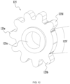
- a certain first difference exists between the radius of the addendum circle of the first drive tooth 125b and the radius of the addendum circle of the second drive tooth 125d, and a certain meshing length exists between the drive tooth on the drive wheel 125 except the first drive tooth 125b and a transmission tooth on the firing pin 161 except a second transmission tooth 1613.
- the ratio of the preceding first difference to the preceding meshing length is higher than or equal to 0.2 and lower than or equal to 0.7.
- the ratio of the preceding first difference to the preceding meshing length is 0.2, 0.3, 0.4, 0.5, 0.6, or 0.7. In an example, as shown in FIG.
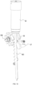
- the transmission teeth 161a of the firing pin 161 are sequentially defined as a first transmission tooth 1612, the second transmission tooth 1613, a third transmission tooth 1614, and the like. It is to be understood that in the process where the firing pin 161 moves from the firing position to the initial position, the first transmission tooth 1612 first meshes with the first drive tooth 125b of the drive wheel 125. That is to say, if the firing pin 161 drives the nail and then moves upward due to the rebound force, the second transmission tooth 1613 first impacts the first drive tooth 125b. In an implementation, the distance between the first transmission tooth 1612 and the second transmission tooth 1613 may be increased.
- the distance between the first transmission tooth 1612 of the firing pin 161 and the second transmission tooth 1613 of the firing pin 161 is S1 and the distance between the second transmission tooth 1613 of the firing pin 161 and the third transmission tooth 1614 of the firing pin 161 is S2, S1 is greater than S2.
- the distance between other adjacent transmission teeth 161a except the first transmission tooth 1612 and the second transmission tooth 1613 is S2.
- the distance between the first transmission tooth 1612 and the second transmission tooth 1613 is increased so that in the process where the firing pin 161 drives the nail and then rebounds, the rebound force is converted into the driving force driving the firing pin 161 to move and is consumed in the process where the firing ping 161 moves the distance S1.
- the ratio of S1 to S2 is lower than 1.
- the ratio of S1 to S2 is higher than or equal to 0.5 and lower than 1.
- the distance between the first transmission tooth 1612 and the second transmission tooth 1613 may be increased according to the magnitude of pressure in the cylinder 13. For example, the higher the pressure in the cylinder 13, the greater the distance S1 set between the first transmission tooth 1612 and the second transmission tooth 1613. It is to be understood that in addition to the pressure in the cylinder 13, S1 is further related to the tooth thickness of the transmission tooth of the firing pin 161 or the modulus of the gear.
- the tooth height H3 of the second transmission tooth 1613 of the firing pin 161 may be reduced, that is, the tooth height of the second transmission tooth 1613 is less than the tooth height of the first transmission tooth 1612 or the tooth height of the third transmission tooth 1614.
- the second transmission tooth 1613 is the transmission tooth with a minimum tooth height among all the transmission teeth 161a. In the process where the firing pin 161 drives the nail and then rebounds, the firing pin 161 is driven by the rebound force to move upward. Since the second transmission tooth 1613 is relatively small, the first drive tooth 125b may impact or may not come into contact with the firing pin 161 in the process where the firing pin 161 moves upward.
- a second difference exists between the tooth height of the first transmission tooth 1612 and the tooth height of the second transmission tooth 1613 or the tooth height of the third transmission tooth 1614, and the ratio of the difference to the preceding meshing length is lower than 1.
- the ratio of the second difference to the preceding meshing length is 0.2, 0.3, 0.4, 0.5, 0.6, 0.7, or the like.
- a controller of the electric motor may control the rotational speed of the electric motor to vary. For example, in the process where the drive wheel 125 drives the firing pin 161 to move from the initial position to the firing position, the controller controls the electric motor to reduce the rotational speed, or when the drive wheel 126 drives the firing pin 161 to move from the initial position to the firing position and start rising from the firing position to the initial position, the rotational speed of the electric motor is reduced. In general, the rotational speed of the electric motor may be reduced in the process in which the firing pin 161 is about to move upward or has moved upward so that the force with which the firing pin 161 rebounds up and down can be reduced.
- the impact force between the drive wheel 125 and the firing pin 161 may be reduced in one manner or through the combination of multiple manners.
- the protruding portion 181 of the second back stopping member 18 abuts against the driven member 172 and the driven member 172 can be pushed by the protruding portion 181 to move so that the locking portion 171 is pushed away and is not in contact with the firing pin 161 and can cooperate with the drive wheel 125 to unlock the firing assembly 16.
- the second section 124f is smooth and continuous, in the case where the drive tooth 125g or the locking portion 171 does not block the firing pin 161, the firing pin 161 is quickly pushed out by the gases in the cylinder 13, thereby implementing the nailing effect.
- the driving force of the drive wheel 125 to drive the transmission teeth 161a to rotate is greater than the elastic force applied to the locking portion 171 by the elastic member 173. Therefore, even if the locking portion 171 applies a certain resistance to the back stopping tooth 161b on the firing pin 161, the drive wheel 125 may drive the firing pin 161 to move upward.
- the size or distance of the tooth on the drive wheel or the tooth on the firing pin is properly adjusted so that the impact between the drive force and the firing pin can be effectively avoided when the firing pin drives the nail and then rebounds, thereby ensuring the service life of the whole nail gun.
Landscapes
- Engineering & Computer Science (AREA)
- Mechanical Engineering (AREA)
- Physics & Mathematics (AREA)
- Fluid Mechanics (AREA)
- Chemical & Material Sciences (AREA)
- Combustion & Propulsion (AREA)
- Portable Nailing Machines And Staplers (AREA)
Claims (15)
- Pistolet à clous (100), comprenant :un boîtier (11) formé avec un espace de logement (111) ;un cylindre (13) connecté au boîtier et utilisé pour stocker des gaz ;un ensemble de percussion (16) disposé au moins partiellement dans le cylindre et apte à se déplacer d'une position initiale à une position de percussion dans le cylindre pour expulser un clou ;un ensemble de sortie de puissance (12) disposé dans l'espace de logement et utilisé pour fournir une force motrice afin d'entraîner l'ensemble de percussion dans le cylindre ; etune roue motrice (125) reliée à un arbre de sortie de l'ensemble de sortie de puissance et utilisée pour entraîner, sous l'action de l'ensemble de sortie de puissance, l'ensemble de percussion dans le cylindre ;dans lequel la roue motrice comprend une première dent d'entraînement (125b) et des secondes dents d'entraînement (125d),caractérisé en ce queun rayon d'un cercle de tête de la première dent d'entraînement est inférieur à un rayon d'un cercle de tête d'une seconde dent d'entraînement, la première dent d'entraînement étant une dent d'entraînement disposée à une extrémité de départ de la roue motrice, et la première dent d'entraînement s'engrène avec l'ensemble de percussion lorsque la roue motrice commence à entraîner le repositionnement de l'ensemble de percussion.
- Le pistolet à clous selon la revendication 1, dans lequel les secondes dents d'entraînement sont les dents d'entraînement de la roue motrice à l'exception de la première dent d'entraînement.
- Le pistolet à clous selon la revendication 1, dans lequel un rapport entre le rayon du cercle de tête de la première dent d'entraînement et le rayon du cercle de tête de la seconde dent d'entraînement est supérieur ou égal à 0,5 et inférieur à 1.
- Le pistolet à clous selon la revendication 1, dans lequel l'ensemble de percussion comprend un piston (162) disposé dans le cylindre et une tige de percussion (161) fixée au piston, et une pluralité de dents de transmission (161a) sont disposées sur la tige de percussion pour s'engrener avec les dents d'entraînement de la roue motrice et être entraînées par la roue motrice dans le cylindre.
- Le pistolet à clous selon la revendication 4, dans lequel la pluralité de dents de transmission comprend une première dent de transmission (1612), une seconde dent de transmission (1613), une troisième dent de transmission (1614), en séquence de la plus proche à la plus éloignée du piston, et une distance entre la seconde dent de transmission et la troisième dent de transmission est inférieure à une distance entre la première dent de transmission et la seconde dent de transmission.
- Le pistolet à clous selon la revendication 5, dans lequel une longueur d'engrènement existant entre une dent d'entraînement de la roue motrice à l'exception de la première dent d'entraînement et une dent de transmission de la tige de percussion à l'exception de la seconde dent de transmission est définie, une première différence existe entre le rayon du cercle de tête de la première dent d'entraînement et le rayon du cercle de tête de la seconde dent d'entraînement, et un rapport entre la première différence et la longueur d'engrènement est supérieur ou égal à 0,2 et inférieur ou égal à 0,7.
- Le pistolet à clous selon la revendication 5, dans lequel une hauteur de dent de la seconde dent de transmission est inférieure à une hauteur de dent de la première dent de transmission ou à une hauteur de dent de la troisième dent de transmission.
- Le pistolet à clous selon la revendication 6, dans lequel une seconde différence existe entre une hauteur de dent de la première dent de transmission et une hauteur de dent de la seconde dent de transmission, et un rapport entre la seconde différence et la longueur d'engrènement est inférieur à 1.
- Le pistolet à clous selon la revendication 1, comprenant en outre un premier élément de butée arrière (17), le premier élément de butée arrière étant utilisé pour bloquer un mouvement de l'ensemble de percussion de la position initiale à la position de percussion ; et un second élément de butée arrière (18), le second élément de butée arrière et la roue motrice étant coaxialement reliés à l'arbre de sortie, et le second élément de butée arrière coopérant avec le premier élément de butée arrière pour bloquer le mouvement de l'ensemble de percussion de la position initiale à la position de percussion.
- Le pistolet à clous selon la revendication 9, dans lequel le second élément de butée arrière est une came avec une portion saillante (181) et une portion non saillante (182).
- Le pistolet à clous selon la revendication 10, dans lequel la roue motrice comprend une première section (125e) où une pluralité de dents d'entraînement (125g) sont réparties uniformément et une seconde section lisse et continue (125f), la portion saillante de la came correspondant à la seconde section de la roue motrice dans une direction axiale de l'arbre de sortie, et la portion non saillante de la came correspondant à la première section de la roue motrice dans la direction axiale de l'arbre de sortie.
- Le pistolet à clous selon la revendication 10, dans lequel une jonction entre la portion saillante de la came et la portion non saillante de la came présente une surface courbe ou une surface plane continue et lisse.
- Le pistolet à clous selon la revendication 10, dans lequel le premier élément de butée arrière comprend : une portion de verrouillage (171), la portion de verrouillage verrouillant l'ensemble de percussion lorsque l'ensemble de percussion est situé dans la position initiale ou à proximité de la position initiale ; un élément entraîné (172), l'élément entraîné pouvant être poussé par la portion saillante de la came pour entraîner la portion de verrouillage à déverrouiller l'ensemble de percussion de sorte que l'ensemble de percussion puisse se déplacer de la position initiale à la position de percussion pour effectuer une action de percussion ; et un élément élastique (173) relié à la portion de verrouillage et capable de pousser la portion de verrouillage pour verrouiller l'ensemble de percussion.
- Le pistolet à clous selon la revendication 13, dans lequel une direction d'une force de poussée exercée sur la portion de verrouillage par l'élément entraîné est opposée à une direction d'une force élastique exercée sur la portion de verrouillage par l'élément élastique.
- Le pistolet à clous selon la revendication 13, dans lequel l'élément élastique comprend un ressort ou un contact à ressort.
Applications Claiming Priority (3)
| Application Number | Priority Date | Filing Date | Title |
|---|---|---|---|
| CN202110978744.0A CN115716256B (zh) | 2021-08-25 | 2021-08-25 | 钉枪 |
| CN202111148196.5A CN116000874B (zh) | 2021-09-29 | 2021-09-29 | 钉枪 |
| PCT/CN2022/106951 WO2023024773A1 (fr) | 2021-08-25 | 2022-07-21 | Cloueuse |
Publications (3)
| Publication Number | Publication Date |
|---|---|
| EP4360809A1 EP4360809A1 (fr) | 2024-05-01 |
| EP4360809A4 EP4360809A4 (fr) | 2024-11-13 |
| EP4360809B1 true EP4360809B1 (fr) | 2025-07-02 |
Family
ID=85321492
Family Applications (1)
| Application Number | Title | Priority Date | Filing Date |
|---|---|---|---|
| EP22860119.1A Active EP4360809B1 (fr) | 2021-08-25 | 2022-07-21 | Cloueuse |
Country Status (4)
| Country | Link |
|---|---|
| US (1) | US12521857B2 (fr) |
| EP (1) | EP4360809B1 (fr) |
| CA (1) | CA3229951A1 (fr) |
| WO (1) | WO2023024773A1 (fr) |
Families Citing this family (2)
| Publication number | Priority date | Publication date | Assignee | Title |
|---|---|---|---|---|
| CN116697009A (zh) * | 2022-02-25 | 2023-09-05 | 台州市大江实业有限公司 | 射钉枪用传动部件、防卡齿组件以及射钉枪 |
| CN117961835A (zh) * | 2024-03-20 | 2024-05-03 | 浙江荣鹏气动工具股份有限公司 | 一种钉枪 |
Family Cites Families (15)
| Publication number | Priority date | Publication date | Assignee | Title |
|---|---|---|---|---|
| US20060180631A1 (en) * | 2005-02-16 | 2006-08-17 | Chris Pedicini | Electric motor driven energy storage device for impacting |
| US8011547B2 (en) | 2007-10-05 | 2011-09-06 | Senco Brands, Inc. | Fastener driving tool using a gas spring |
| US8636185B2 (en) | 2010-11-15 | 2014-01-28 | Illinois Tool Works Inc. | Fastener advance delay for fastener driving tool |
| WO2016127101A1 (fr) | 2015-02-06 | 2016-08-11 | Milwaukee Electric Tool Corporation | Dispositif d'entraînement de fixation alimenté par ressort à gaz |
| CN107708934B (zh) * | 2015-06-10 | 2022-01-11 | 工机控股株式会社 | 打入机 |
| CN105289792B (zh) * | 2015-09-24 | 2018-04-24 | 潘济安 | 齿轮齿条式往复冲击装置 |
| CN105818099B (zh) | 2016-05-26 | 2017-11-17 | 杭州科龙电器工具股份有限公司 | 使用气弹簧的电动钉枪 |
| CN116276821A (zh) * | 2017-04-26 | 2023-06-23 | 工机控股株式会社 | 打入机 |
| TWI804476B (zh) | 2017-11-02 | 2023-06-11 | 鑽全實業股份有限公司 | 氣壓式電動釘槍 |
| CN111791187B (zh) * | 2019-04-04 | 2023-06-20 | 南京泉峰科技有限公司 | 钉枪 |
| TW202039176A (zh) * | 2019-04-25 | 2020-11-01 | 鑽全實業股份有限公司 | 氣壓式釘槍及其舉升輪 |
| CN110385675B (zh) | 2019-07-10 | 2022-03-08 | 南京腾亚精工科技股份有限公司 | 一种紧固件打击工具 |
| CN211220544U (zh) * | 2019-10-30 | 2020-08-11 | 重庆弘愿工具(集团)有限公司 | 一种电动钉枪 |
| CN214055139U (zh) | 2019-11-01 | 2021-08-27 | 南京德朔实业有限公司 | 钉枪 |
| CN113070849B (zh) * | 2020-01-06 | 2024-07-19 | 朱益民 | 一种打钉工具 |
-
2022
- 2022-07-21 WO PCT/CN2022/106951 patent/WO2023024773A1/fr not_active Ceased
- 2022-07-21 CA CA3229951A patent/CA3229951A1/fr active Pending
- 2022-07-21 EP EP22860119.1A patent/EP4360809B1/fr active Active
-
2024
- 2024-01-26 US US18/424,343 patent/US12521857B2/en active Active
Also Published As
| Publication number | Publication date |
|---|---|
| EP4360809A1 (fr) | 2024-05-01 |
| US20240246211A1 (en) | 2024-07-25 |
| EP4360809A4 (fr) | 2024-11-13 |
| CA3229951A1 (fr) | 2023-03-02 |
| WO2023024773A1 (fr) | 2023-03-02 |
| US12521857B2 (en) | 2026-01-13 |
Similar Documents
| Publication | Publication Date | Title |
|---|---|---|
| US12521857B2 (en) | Nail gun | |
| CN109605285B (zh) | 一种打钉枪 | |
| US11400573B2 (en) | Pneumatic tool | |
| EP2176035B1 (fr) | Dispositif de marteau cloueur | |
| CN100519087C (zh) | 打入作业工具 | |
| CN102844154B (zh) | 冲击装置 | |
| TW202039176A (zh) | 氣壓式釘槍及其舉升輪 | |
| CN111791187B (zh) | 钉枪 | |
| CN102642193A (zh) | 用于紧固件驱动设备具有旁路的空射闭锁件 | |
| US11667020B2 (en) | Driving tool | |
| TW202039180A (zh) | 氣動線性緊固件驅動工具 | |
| CN214055139U (zh) | 钉枪 | |
| CN116061134B (zh) | 钉枪 | |
| CN116000874B (zh) | 钉枪 | |
| EP4296005A1 (fr) | Ensemble d'engrenages de levage et pistolet à clous électrique le comprenant | |
| CN212020643U (zh) | 一种齿条锁扣式紧固件打入机 | |
| CN215037163U (zh) | 钉枪 | |
| CN111331557B (zh) | 一种用于紧固件打入机的驱动机构 | |
| CN220030111U (zh) | 一种斜排射钉击打工具 | |
| CN221539660U (zh) | 钉枪 | |
| CN220561458U (zh) | 枪针提举机构及钉枪 | |
| CN115716256B (zh) | 钉枪 | |
| CN220051694U (zh) | 撞针驱动机构及钉枪 | |
| CN220719194U (zh) | 改良型紧固件打入机 | |
| CN223545173U (zh) | 动力装置及钉枪 |
Legal Events
| Date | Code | Title | Description |
|---|---|---|---|
| STAA | Information on the status of an ep patent application or granted ep patent |
Free format text: STATUS: THE INTERNATIONAL PUBLICATION HAS BEEN MADE |
|
| PUAI | Public reference made under article 153(3) epc to a published international application that has entered the european phase |
Free format text: ORIGINAL CODE: 0009012 |
|
| STAA | Information on the status of an ep patent application or granted ep patent |
Free format text: STATUS: REQUEST FOR EXAMINATION WAS MADE |
|
| 17P | Request for examination filed |
Effective date: 20240125 |
|
| AK | Designated contracting states |
Kind code of ref document: A1 Designated state(s): AL AT BE BG CH CY CZ DE DK EE ES FI FR GB GR HR HU IE IS IT LI LT LU LV MC MK MT NL NO PL PT RO RS SE SI SK SM TR |
|
| A4 | Supplementary search report drawn up and despatched |
Effective date: 20241015 |
|
| RIC1 | Information provided on ipc code assigned before grant |
Ipc: B25D 11/10 20060101ALI20241009BHEP Ipc: B25D 11/06 20060101ALI20241009BHEP Ipc: B25C 1/06 20060101ALI20241009BHEP Ipc: B25C 1/04 20060101AFI20241009BHEP |
|
| DAV | Request for validation of the european patent (deleted) | ||
| DAX | Request for extension of the european patent (deleted) | ||
| GRAP | Despatch of communication of intention to grant a patent |
Free format text: ORIGINAL CODE: EPIDOSNIGR1 |
|
| STAA | Information on the status of an ep patent application or granted ep patent |
Free format text: STATUS: GRANT OF PATENT IS INTENDED |
|
| GRAS | Grant fee paid |
Free format text: ORIGINAL CODE: EPIDOSNIGR3 |
|
| GRAA | (expected) grant |
Free format text: ORIGINAL CODE: 0009210 |
|
| STAA | Information on the status of an ep patent application or granted ep patent |
Free format text: STATUS: THE PATENT HAS BEEN GRANTED |
|
| INTG | Intention to grant announced |
Effective date: 20250519 |
|
| AK | Designated contracting states |
Kind code of ref document: B1 Designated state(s): AL AT BE BG CH CY CZ DE DK EE ES FI FR GB GR HR HU IE IS IT LI LT LU LV MC MK MT NL NO PL PT RO RS SE SI SK SM TR |
|
| REG | Reference to a national code |
Ref country code: GB Ref legal event code: FG4D |
|
| REG | Reference to a national code |
Ref country code: CH Ref legal event code: EP |
|
| REG | Reference to a national code |
Ref country code: DE Ref legal event code: R096 Ref document number: 602022017107 Country of ref document: DE |
|
| REG | Reference to a national code |
Ref country code: IE Ref legal event code: FG4D |
|
| PGFP | Annual fee paid to national office [announced via postgrant information from national office to epo] |
Ref country code: DE Payment date: 20250708 Year of fee payment: 4 |
|
| PGFP | Annual fee paid to national office [announced via postgrant information from national office to epo] |
Ref country code: AT Payment date: 20251020 Year of fee payment: 4 Ref country code: FR Payment date: 20250708 Year of fee payment: 4 |
|
| REG | Reference to a national code |
Ref country code: NL Ref legal event code: MP Effective date: 20250702 |
|
| PG25 | Lapsed in a contracting state [announced via postgrant information from national office to epo] |
Ref country code: PT Free format text: LAPSE BECAUSE OF FAILURE TO SUBMIT A TRANSLATION OF THE DESCRIPTION OR TO PAY THE FEE WITHIN THE PRESCRIBED TIME-LIMIT Effective date: 20251103 |
|
| PG25 | Lapsed in a contracting state [announced via postgrant information from national office to epo] |
Ref country code: NL Free format text: LAPSE BECAUSE OF FAILURE TO SUBMIT A TRANSLATION OF THE DESCRIPTION OR TO PAY THE FEE WITHIN THE PRESCRIBED TIME-LIMIT Effective date: 20250702 |
|
| REG | Reference to a national code |
Ref country code: AT Ref legal event code: MK05 Ref document number: 1808734 Country of ref document: AT Kind code of ref document: T Effective date: 20250702 |
|
| PG25 | Lapsed in a contracting state [announced via postgrant information from national office to epo] |
Ref country code: IS Free format text: LAPSE BECAUSE OF FAILURE TO SUBMIT A TRANSLATION OF THE DESCRIPTION OR TO PAY THE FEE WITHIN THE PRESCRIBED TIME-LIMIT Effective date: 20251102 |
|
| PG25 | Lapsed in a contracting state [announced via postgrant information from national office to epo] |
Ref country code: NO Free format text: LAPSE BECAUSE OF FAILURE TO SUBMIT A TRANSLATION OF THE DESCRIPTION OR TO PAY THE FEE WITHIN THE PRESCRIBED TIME-LIMIT Effective date: 20251002 |
|
| REG | Reference to a national code |
Ref country code: LT Ref legal event code: MG9D |
|
| PG25 | Lapsed in a contracting state [announced via postgrant information from national office to epo] |
Ref country code: AT Free format text: LAPSE BECAUSE OF FAILURE TO SUBMIT A TRANSLATION OF THE DESCRIPTION OR TO PAY THE FEE WITHIN THE PRESCRIBED TIME-LIMIT Effective date: 20250702 |
|
| PG25 | Lapsed in a contracting state [announced via postgrant information from national office to epo] |
Ref country code: FI Free format text: LAPSE BECAUSE OF FAILURE TO SUBMIT A TRANSLATION OF THE DESCRIPTION OR TO PAY THE FEE WITHIN THE PRESCRIBED TIME-LIMIT Effective date: 20250702 |
|
| PG25 | Lapsed in a contracting state [announced via postgrant information from national office to epo] |
Ref country code: HR Free format text: LAPSE BECAUSE OF FAILURE TO SUBMIT A TRANSLATION OF THE DESCRIPTION OR TO PAY THE FEE WITHIN THE PRESCRIBED TIME-LIMIT Effective date: 20250702 |
|
| PG25 | Lapsed in a contracting state [announced via postgrant information from national office to epo] |
Ref country code: GR Free format text: LAPSE BECAUSE OF FAILURE TO SUBMIT A TRANSLATION OF THE DESCRIPTION OR TO PAY THE FEE WITHIN THE PRESCRIBED TIME-LIMIT Effective date: 20251003 |
|
| PG25 | Lapsed in a contracting state [announced via postgrant information from national office to epo] |
Ref country code: CZ Free format text: LAPSE BECAUSE OF FAILURE TO SUBMIT A TRANSLATION OF THE DESCRIPTION OR TO PAY THE FEE WITHIN THE PRESCRIBED TIME-LIMIT Effective date: 20250702 Ref country code: SE Free format text: LAPSE BECAUSE OF FAILURE TO SUBMIT A TRANSLATION OF THE DESCRIPTION OR TO PAY THE FEE WITHIN THE PRESCRIBED TIME-LIMIT Effective date: 20250702 |
|
| PG25 | Lapsed in a contracting state [announced via postgrant information from national office to epo] |
Ref country code: LV Free format text: LAPSE BECAUSE OF FAILURE TO SUBMIT A TRANSLATION OF THE DESCRIPTION OR TO PAY THE FEE WITHIN THE PRESCRIBED TIME-LIMIT Effective date: 20250702 |
|
| PG25 | Lapsed in a contracting state [announced via postgrant information from national office to epo] |
Ref country code: BG Free format text: LAPSE BECAUSE OF FAILURE TO SUBMIT A TRANSLATION OF THE DESCRIPTION OR TO PAY THE FEE WITHIN THE PRESCRIBED TIME-LIMIT Effective date: 20250702 Ref country code: PL Free format text: LAPSE BECAUSE OF FAILURE TO SUBMIT A TRANSLATION OF THE DESCRIPTION OR TO PAY THE FEE WITHIN THE PRESCRIBED TIME-LIMIT Effective date: 20250702 |
|
| PG25 | Lapsed in a contracting state [announced via postgrant information from national office to epo] |
Ref country code: RS Free format text: LAPSE BECAUSE OF FAILURE TO SUBMIT A TRANSLATION OF THE DESCRIPTION OR TO PAY THE FEE WITHIN THE PRESCRIBED TIME-LIMIT Effective date: 20251002 |
|
| PG25 | Lapsed in a contracting state [announced via postgrant information from national office to epo] |
Ref country code: ES Free format text: LAPSE BECAUSE OF FAILURE TO SUBMIT A TRANSLATION OF THE DESCRIPTION OR TO PAY THE FEE WITHIN THE PRESCRIBED TIME-LIMIT Effective date: 20250702 |
|
| REG | Reference to a national code |
Ref country code: CH Ref legal event code: H13 Free format text: ST27 STATUS EVENT CODE: U-0-0-H10-H13 (AS PROVIDED BY THE NATIONAL OFFICE) Effective date: 20260224 |
|
| PG25 | Lapsed in a contracting state [announced via postgrant information from national office to epo] |
Ref country code: RO Free format text: LAPSE BECAUSE OF FAILURE TO SUBMIT A TRANSLATION OF THE DESCRIPTION OR TO PAY THE FEE WITHIN THE PRESCRIBED TIME-LIMIT Effective date: 20250702 Ref country code: LU Free format text: LAPSE BECAUSE OF NON-PAYMENT OF DUE FEES Effective date: 20250721 |
|
| REG | Reference to a national code |
Ref country code: BE Ref legal event code: MM Effective date: 20250731 |
|
| PG25 | Lapsed in a contracting state [announced via postgrant information from national office to epo] |
Ref country code: SM Free format text: LAPSE BECAUSE OF FAILURE TO SUBMIT A TRANSLATION OF THE DESCRIPTION OR TO PAY THE FEE WITHIN THE PRESCRIBED TIME-LIMIT Effective date: 20250702 |
|
| PG25 | Lapsed in a contracting state [announced via postgrant information from national office to epo] |
Ref country code: DK Free format text: LAPSE BECAUSE OF FAILURE TO SUBMIT A TRANSLATION OF THE DESCRIPTION OR TO PAY THE FEE WITHIN THE PRESCRIBED TIME-LIMIT Effective date: 20250702 |
|
| PG25 | Lapsed in a contracting state [announced via postgrant information from national office to epo] |
Ref country code: IT Free format text: LAPSE BECAUSE OF FAILURE TO SUBMIT A TRANSLATION OF THE DESCRIPTION OR TO PAY THE FEE WITHIN THE PRESCRIBED TIME-LIMIT Effective date: 20250702 Ref country code: BE Free format text: LAPSE BECAUSE OF NON-PAYMENT OF DUE FEES Effective date: 20250731 |
|
| PG25 | Lapsed in a contracting state [announced via postgrant information from national office to epo] |
Ref country code: CH Free format text: LAPSE BECAUSE OF NON-PAYMENT OF DUE FEES Effective date: 20250731 |
|
| PG25 | Lapsed in a contracting state [announced via postgrant information from national office to epo] |
Ref country code: SK Free format text: LAPSE BECAUSE OF FAILURE TO SUBMIT A TRANSLATION OF THE DESCRIPTION OR TO PAY THE FEE WITHIN THE PRESCRIBED TIME-LIMIT Effective date: 20250702 Ref country code: EE Free format text: LAPSE BECAUSE OF FAILURE TO SUBMIT A TRANSLATION OF THE DESCRIPTION OR TO PAY THE FEE WITHIN THE PRESCRIBED TIME-LIMIT Effective date: 20250702 |
|
| PLBE | No opposition filed within time limit |
Free format text: ORIGINAL CODE: 0009261 |
|
| STAA | Information on the status of an ep patent application or granted ep patent |
Free format text: STATUS: NO OPPOSITION FILED WITHIN TIME LIMIT |