EP4360921A2 - Réglage de système de dynamique de marche de véhicule - Google Patents
Réglage de système de dynamique de marche de véhicule Download PDFInfo
- Publication number
- EP4360921A2 EP4360921A2 EP23205850.3A EP23205850A EP4360921A2 EP 4360921 A2 EP4360921 A2 EP 4360921A2 EP 23205850 A EP23205850 A EP 23205850A EP 4360921 A2 EP4360921 A2 EP 4360921A2
- Authority
- EP
- European Patent Office
- Prior art keywords
- vehicle
- tyre
- contact patch
- adjusting
- control system
- Prior art date
- Legal status (The legal status is an assumption and is not a legal conclusion. Google has not performed a legal analysis and makes no representation as to the accuracy of the status listed.)
- Pending
Links
Images

Classifications
-
- B—PERFORMING OPERATIONS; TRANSPORTING
- B60—VEHICLES IN GENERAL
- B60W—CONJOINT CONTROL OF VEHICLE SUB-UNITS OF DIFFERENT TYPE OR DIFFERENT FUNCTION; CONTROL SYSTEMS SPECIALLY ADAPTED FOR HYBRID VEHICLES; ROAD VEHICLE DRIVE CONTROL SYSTEMS FOR PURPOSES NOT RELATED TO THE CONTROL OF A PARTICULAR SUB-UNIT
- B60W30/00—Purposes of road vehicle drive control systems not related to the control of a particular sub-unit, e.g. of systems using conjoint control of vehicle sub-units
- B60W30/02—Control of vehicle driving stability
- B60W30/04—Control of vehicle driving stability related to roll-over prevention
-
- B—PERFORMING OPERATIONS; TRANSPORTING
- B60—VEHICLES IN GENERAL
- B60G—VEHICLE SUSPENSION ARRANGEMENTS
- B60G17/00—Resilient suspensions having means for adjusting the spring or vibration-damper characteristics, for regulating the distance between a supporting surface and a sprung part of vehicle or for locking suspension during use to meet varying vehicular or surface conditions, e.g. due to speed or load
- B60G17/015—Resilient suspensions having means for adjusting the spring or vibration-damper characteristics, for regulating the distance between a supporting surface and a sprung part of vehicle or for locking suspension during use to meet varying vehicular or surface conditions, e.g. due to speed or load the regulating means comprising electric or electronic elements
- B60G17/016—Resilient suspensions having means for adjusting the spring or vibration-damper characteristics, for regulating the distance between a supporting surface and a sprung part of vehicle or for locking suspension during use to meet varying vehicular or surface conditions, e.g. due to speed or load the regulating means comprising electric or electronic elements characterised by their responsiveness, when the vehicle is travelling, to specific motion, a specific condition, or driver input
- B60G17/0162—Resilient suspensions having means for adjusting the spring or vibration-damper characteristics, for regulating the distance between a supporting surface and a sprung part of vehicle or for locking suspension during use to meet varying vehicular or surface conditions, e.g. due to speed or load the regulating means comprising electric or electronic elements characterised by their responsiveness, when the vehicle is travelling, to specific motion, a specific condition, or driver input mainly during a motion involving steering operation, e.g. cornering, overtaking
-
- B—PERFORMING OPERATIONS; TRANSPORTING
- B60—VEHICLES IN GENERAL
- B60C—VEHICLE TYRES; TYRE INFLATION; TYRE CHANGING; CONNECTING VALVES TO INFLATABLE ELASTIC BODIES IN GENERAL; DEVICES OR ARRANGEMENTS RELATED TO TYRES
- B60C23/00—Devices for measuring, signalling, controlling, or distributing tyre pressure or temperature, specially adapted for mounting on vehicles; Arrangement of tyre inflating devices on vehicles, e.g. of pumps or of tanks; Tyre cooling arrangements
- B60C23/02—Signalling devices actuated by tyre pressure
-
- B—PERFORMING OPERATIONS; TRANSPORTING
- B60—VEHICLES IN GENERAL
- B60G—VEHICLE SUSPENSION ARRANGEMENTS
- B60G17/00—Resilient suspensions having means for adjusting the spring or vibration-damper characteristics, for regulating the distance between a supporting surface and a sprung part of vehicle or for locking suspension during use to meet varying vehicular or surface conditions, e.g. due to speed or load
- B60G17/015—Resilient suspensions having means for adjusting the spring or vibration-damper characteristics, for regulating the distance between a supporting surface and a sprung part of vehicle or for locking suspension during use to meet varying vehicular or surface conditions, e.g. due to speed or load the regulating means comprising electric or electronic elements
- B60G17/016—Resilient suspensions having means for adjusting the spring or vibration-damper characteristics, for regulating the distance between a supporting surface and a sprung part of vehicle or for locking suspension during use to meet varying vehicular or surface conditions, e.g. due to speed or load the regulating means comprising electric or electronic elements characterised by their responsiveness, when the vehicle is travelling, to specific motion, a specific condition, or driver input
- B60G17/0165—Resilient suspensions having means for adjusting the spring or vibration-damper characteristics, for regulating the distance between a supporting surface and a sprung part of vehicle or for locking suspension during use to meet varying vehicular or surface conditions, e.g. due to speed or load the regulating means comprising electric or electronic elements characterised by their responsiveness, when the vehicle is travelling, to specific motion, a specific condition, or driver input to an external condition, e.g. rough road surface, side wind
-
- B—PERFORMING OPERATIONS; TRANSPORTING
- B60—VEHICLES IN GENERAL
- B60G—VEHICLE SUSPENSION ARRANGEMENTS
- B60G17/00—Resilient suspensions having means for adjusting the spring or vibration-damper characteristics, for regulating the distance between a supporting surface and a sprung part of vehicle or for locking suspension during use to meet varying vehicular or surface conditions, e.g. due to speed or load
- B60G17/015—Resilient suspensions having means for adjusting the spring or vibration-damper characteristics, for regulating the distance between a supporting surface and a sprung part of vehicle or for locking suspension during use to meet varying vehicular or surface conditions, e.g. due to speed or load the regulating means comprising electric or electronic elements
- B60G17/018—Resilient suspensions having means for adjusting the spring or vibration-damper characteristics, for regulating the distance between a supporting surface and a sprung part of vehicle or for locking suspension during use to meet varying vehicular or surface conditions, e.g. due to speed or load the regulating means comprising electric or electronic elements characterised by the use of a specific signal treatment or control method
- B60G17/0182—Resilient suspensions having means for adjusting the spring or vibration-damper characteristics, for regulating the distance between a supporting surface and a sprung part of vehicle or for locking suspension during use to meet varying vehicular or surface conditions, e.g. due to speed or load the regulating means comprising electric or electronic elements characterised by the use of a specific signal treatment or control method involving parameter estimation, e.g. observer, Kalman filter
-
- B—PERFORMING OPERATIONS; TRANSPORTING
- B60—VEHICLES IN GENERAL
- B60G—VEHICLE SUSPENSION ARRANGEMENTS
- B60G17/00—Resilient suspensions having means for adjusting the spring or vibration-damper characteristics, for regulating the distance between a supporting surface and a sprung part of vehicle or for locking suspension during use to meet varying vehicular or surface conditions, e.g. due to speed or load
- B60G17/015—Resilient suspensions having means for adjusting the spring or vibration-damper characteristics, for regulating the distance between a supporting surface and a sprung part of vehicle or for locking suspension during use to meet varying vehicular or surface conditions, e.g. due to speed or load the regulating means comprising electric or electronic elements
- B60G17/0195—Resilient suspensions having means for adjusting the spring or vibration-damper characteristics, for regulating the distance between a supporting surface and a sprung part of vehicle or for locking suspension during use to meet varying vehicular or surface conditions, e.g. due to speed or load the regulating means comprising electric or electronic elements characterised by the regulation being combined with other vehicle control systems
-
- B—PERFORMING OPERATIONS; TRANSPORTING
- B60—VEHICLES IN GENERAL
- B60T—VEHICLE BRAKE CONTROL SYSTEMS OR PARTS THEREOF; BRAKE CONTROL SYSTEMS OR PARTS THEREOF, IN GENERAL; ARRANGEMENT OF BRAKING ELEMENTS ON VEHICLES IN GENERAL; PORTABLE DEVICES FOR PREVENTING UNWANTED MOVEMENT OF VEHICLES; VEHICLE MODIFICATIONS TO FACILITATE COOLING OF BRAKES
- B60T8/00—Arrangements for adjusting wheel-braking force to meet varying vehicular or ground-surface conditions, e.g. limiting or varying distribution of braking force
- B60T8/17—Using electrical or electronic regulation means to control braking
- B60T8/1755—Brake regulation specially adapted to control the stability of the vehicle, e.g. taking into account yaw rate or transverse acceleration in a curve
- B60T8/17554—Brake regulation specially adapted to control the stability of the vehicle, e.g. taking into account yaw rate or transverse acceleration in a curve specially adapted for enhancing stability around the vehicles longitudinal axle, i.e. roll-over prevention
-
- B—PERFORMING OPERATIONS; TRANSPORTING
- B60—VEHICLES IN GENERAL
- B60W—CONJOINT CONTROL OF VEHICLE SUB-UNITS OF DIFFERENT TYPE OR DIFFERENT FUNCTION; CONTROL SYSTEMS SPECIALLY ADAPTED FOR HYBRID VEHICLES; ROAD VEHICLE DRIVE CONTROL SYSTEMS FOR PURPOSES NOT RELATED TO THE CONTROL OF A PARTICULAR SUB-UNIT
- B60W10/00—Conjoint control of vehicle sub-units of different type or different function
- B60W10/20—Conjoint control of vehicle sub-units of different type or different function including control of steering systems
-
- B—PERFORMING OPERATIONS; TRANSPORTING
- B60—VEHICLES IN GENERAL
- B60W—CONJOINT CONTROL OF VEHICLE SUB-UNITS OF DIFFERENT TYPE OR DIFFERENT FUNCTION; CONTROL SYSTEMS SPECIALLY ADAPTED FOR HYBRID VEHICLES; ROAD VEHICLE DRIVE CONTROL SYSTEMS FOR PURPOSES NOT RELATED TO THE CONTROL OF A PARTICULAR SUB-UNIT
- B60W10/00—Conjoint control of vehicle sub-units of different type or different function
- B60W10/22—Conjoint control of vehicle sub-units of different type or different function including control of suspension systems
-
- B—PERFORMING OPERATIONS; TRANSPORTING
- B60—VEHICLES IN GENERAL
- B60W—CONJOINT CONTROL OF VEHICLE SUB-UNITS OF DIFFERENT TYPE OR DIFFERENT FUNCTION; CONTROL SYSTEMS SPECIALLY ADAPTED FOR HYBRID VEHICLES; ROAD VEHICLE DRIVE CONTROL SYSTEMS FOR PURPOSES NOT RELATED TO THE CONTROL OF A PARTICULAR SUB-UNIT
- B60W40/00—Estimation or calculation of non-directly measurable driving parameters for road vehicle drive control systems not related to the control of a particular sub unit, e.g. by using mathematical models
- B60W40/02—Estimation or calculation of non-directly measurable driving parameters for road vehicle drive control systems not related to the control of a particular sub unit, e.g. by using mathematical models related to ambient conditions
- B60W40/06—Road conditions
- B60W40/064—Degree of grip
-
- B—PERFORMING OPERATIONS; TRANSPORTING
- B60—VEHICLES IN GENERAL
- B60W—CONJOINT CONTROL OF VEHICLE SUB-UNITS OF DIFFERENT TYPE OR DIFFERENT FUNCTION; CONTROL SYSTEMS SPECIALLY ADAPTED FOR HYBRID VEHICLES; ROAD VEHICLE DRIVE CONTROL SYSTEMS FOR PURPOSES NOT RELATED TO THE CONTROL OF A PARTICULAR SUB-UNIT
- B60W40/00—Estimation or calculation of non-directly measurable driving parameters for road vehicle drive control systems not related to the control of a particular sub unit, e.g. by using mathematical models
- B60W40/02—Estimation or calculation of non-directly measurable driving parameters for road vehicle drive control systems not related to the control of a particular sub unit, e.g. by using mathematical models related to ambient conditions
- B60W40/06—Road conditions
- B60W40/068—Road friction coefficient
-
- B—PERFORMING OPERATIONS; TRANSPORTING
- B60—VEHICLES IN GENERAL
- B60W—CONJOINT CONTROL OF VEHICLE SUB-UNITS OF DIFFERENT TYPE OR DIFFERENT FUNCTION; CONTROL SYSTEMS SPECIALLY ADAPTED FOR HYBRID VEHICLES; ROAD VEHICLE DRIVE CONTROL SYSTEMS FOR PURPOSES NOT RELATED TO THE CONTROL OF A PARTICULAR SUB-UNIT
- B60W40/00—Estimation or calculation of non-directly measurable driving parameters for road vehicle drive control systems not related to the control of a particular sub unit, e.g. by using mathematical models
- B60W40/10—Estimation or calculation of non-directly measurable driving parameters for road vehicle drive control systems not related to the control of a particular sub unit, e.g. by using mathematical models related to vehicle motion
- B60W40/112—Roll movement
-
- B—PERFORMING OPERATIONS; TRANSPORTING
- B62—LAND VEHICLES FOR TRAVELLING OTHERWISE THAN ON RAILS
- B62D—MOTOR VEHICLES; TRAILERS
- B62D37/00—Stabilising vehicle bodies without controlling suspension arrangements
- B62D37/02—Stabilising vehicle bodies without controlling suspension arrangements by aerodynamic means
-
- B—PERFORMING OPERATIONS; TRANSPORTING
- B60—VEHICLES IN GENERAL
- B60G—VEHICLE SUSPENSION ARRANGEMENTS
- B60G2204/00—Indexing codes related to suspensions per se or to auxiliary parts
- B60G2204/10—Mounting of suspension elements
- B60G2204/11—Mounting of sensors thereon
- B60G2204/113—Tyre related sensors
-
- B—PERFORMING OPERATIONS; TRANSPORTING
- B60—VEHICLES IN GENERAL
- B60G—VEHICLE SUSPENSION ARRANGEMENTS
- B60G2300/00—Indexing codes relating to the type of vehicle
- B60G2300/27—Racing vehicles, e.g. F1
-
- B—PERFORMING OPERATIONS; TRANSPORTING
- B60—VEHICLES IN GENERAL
- B60G—VEHICLE SUSPENSION ARRANGEMENTS
- B60G2400/00—Indexing codes relating to detected, measured or calculated conditions or factors
- B60G2400/20—Speed
- B60G2400/204—Vehicle speed
-
- B—PERFORMING OPERATIONS; TRANSPORTING
- B60—VEHICLES IN GENERAL
- B60G—VEHICLE SUSPENSION ARRANGEMENTS
- B60G2400/00—Indexing codes relating to detected, measured or calculated conditions or factors
- B60G2400/20—Speed
- B60G2400/208—Speed of wheel rotation
-
- B—PERFORMING OPERATIONS; TRANSPORTING
- B60—VEHICLES IN GENERAL
- B60G—VEHICLE SUSPENSION ARRANGEMENTS
- B60G2400/00—Indexing codes relating to detected, measured or calculated conditions or factors
- B60G2400/30—Propulsion unit conditions
- B60G2400/302—Selected gear ratio; Transmission function
-
- B—PERFORMING OPERATIONS; TRANSPORTING
- B60—VEHICLES IN GENERAL
- B60G—VEHICLE SUSPENSION ARRANGEMENTS
- B60G2400/00—Indexing codes relating to detected, measured or calculated conditions or factors
- B60G2400/30—Propulsion unit conditions
- B60G2400/38—Speed of engine rotation
-
- B—PERFORMING OPERATIONS; TRANSPORTING
- B60—VEHICLES IN GENERAL
- B60G—VEHICLE SUSPENSION ARRANGEMENTS
- B60G2400/00—Indexing codes relating to detected, measured or calculated conditions or factors
- B60G2400/30—Propulsion unit conditions
- B60G2400/39—Brake pedal position
-
- B—PERFORMING OPERATIONS; TRANSPORTING
- B60—VEHICLES IN GENERAL
- B60G—VEHICLE SUSPENSION ARRANGEMENTS
- B60G2400/00—Indexing codes relating to detected, measured or calculated conditions or factors
- B60G2400/50—Pressure
- B60G2400/52—Pressure in tyre
-
- B—PERFORMING OPERATIONS; TRANSPORTING
- B60—VEHICLES IN GENERAL
- B60G—VEHICLE SUSPENSION ARRANGEMENTS
- B60G2400/00—Indexing codes relating to detected, measured or calculated conditions or factors
- B60G2400/60—Load
-
- B—PERFORMING OPERATIONS; TRANSPORTING
- B60—VEHICLES IN GENERAL
- B60G—VEHICLE SUSPENSION ARRANGEMENTS
- B60G2400/00—Indexing codes relating to detected, measured or calculated conditions or factors
- B60G2400/90—Other conditions or factors
-
- B—PERFORMING OPERATIONS; TRANSPORTING
- B60—VEHICLES IN GENERAL
- B60G—VEHICLE SUSPENSION ARRANGEMENTS
- B60G2500/00—Indexing codes relating to the regulated action or device
- B60G2500/10—Damping action or damper
-
- B—PERFORMING OPERATIONS; TRANSPORTING
- B60—VEHICLES IN GENERAL
- B60G—VEHICLE SUSPENSION ARRANGEMENTS
- B60G2500/00—Indexing codes relating to the regulated action or device
- B60G2500/30—Height or ground clearance
-
- B—PERFORMING OPERATIONS; TRANSPORTING
- B60—VEHICLES IN GENERAL
- B60G—VEHICLE SUSPENSION ARRANGEMENTS
- B60G2800/00—Indexing codes relating to the type of movement or to the condition of the vehicle and to the end result to be achieved by the control action
- B60G2800/01—Attitude or posture control
-
- B—PERFORMING OPERATIONS; TRANSPORTING
- B60—VEHICLES IN GENERAL
- B60G—VEHICLE SUSPENSION ARRANGEMENTS
- B60G2800/00—Indexing codes relating to the type of movement or to the condition of the vehicle and to the end result to be achieved by the control action
- B60G2800/01—Attitude or posture control
- B60G2800/012—Rolling condition
-
- B—PERFORMING OPERATIONS; TRANSPORTING
- B60—VEHICLES IN GENERAL
- B60G—VEHICLE SUSPENSION ARRANGEMENTS
- B60G2800/00—Indexing codes relating to the type of movement or to the condition of the vehicle and to the end result to be achieved by the control action
- B60G2800/21—Traction, slip, skid or slide control
-
- B—PERFORMING OPERATIONS; TRANSPORTING
- B60—VEHICLES IN GENERAL
- B60G—VEHICLE SUSPENSION ARRANGEMENTS
- B60G2800/00—Indexing codes relating to the type of movement or to the condition of the vehicle and to the end result to be achieved by the control action
- B60G2800/21—Traction, slip, skid or slide control
- B60G2800/212—Transversal; Side-slip during cornering
-
- B—PERFORMING OPERATIONS; TRANSPORTING
- B60—VEHICLES IN GENERAL
- B60T—VEHICLE BRAKE CONTROL SYSTEMS OR PARTS THEREOF; BRAKE CONTROL SYSTEMS OR PARTS THEREOF, IN GENERAL; ARRANGEMENT OF BRAKING ELEMENTS ON VEHICLES IN GENERAL; PORTABLE DEVICES FOR PREVENTING UNWANTED MOVEMENT OF VEHICLES; VEHICLE MODIFICATIONS TO FACILITATE COOLING OF BRAKES
- B60T2230/00—Monitoring, detecting special vehicle behaviour; Counteracting thereof
- B60T2230/02—Side slip angle, attitude angle, floating angle, drift angle
-
- B—PERFORMING OPERATIONS; TRANSPORTING
- B60—VEHICLES IN GENERAL
- B60T—VEHICLE BRAKE CONTROL SYSTEMS OR PARTS THEREOF; BRAKE CONTROL SYSTEMS OR PARTS THEREOF, IN GENERAL; ARRANGEMENT OF BRAKING ELEMENTS ON VEHICLES IN GENERAL; PORTABLE DEVICES FOR PREVENTING UNWANTED MOVEMENT OF VEHICLES; VEHICLE MODIFICATIONS TO FACILITATE COOLING OF BRAKES
- B60T2240/00—Monitoring, detecting wheel/tyre behaviour; counteracting thereof
- B60T2240/03—Tyre sensors
-
- B—PERFORMING OPERATIONS; TRANSPORTING
- B60—VEHICLES IN GENERAL
- B60T—VEHICLE BRAKE CONTROL SYSTEMS OR PARTS THEREOF; BRAKE CONTROL SYSTEMS OR PARTS THEREOF, IN GENERAL; ARRANGEMENT OF BRAKING ELEMENTS ON VEHICLES IN GENERAL; PORTABLE DEVICES FOR PREVENTING UNWANTED MOVEMENT OF VEHICLES; VEHICLE MODIFICATIONS TO FACILITATE COOLING OF BRAKES
- B60T2260/00—Interaction of vehicle brake system with other systems
- B60T2260/06—Active Suspension System
-
- B—PERFORMING OPERATIONS; TRANSPORTING
- B60—VEHICLES IN GENERAL
- B60W—CONJOINT CONTROL OF VEHICLE SUB-UNITS OF DIFFERENT TYPE OR DIFFERENT FUNCTION; CONTROL SYSTEMS SPECIALLY ADAPTED FOR HYBRID VEHICLES; ROAD VEHICLE DRIVE CONTROL SYSTEMS FOR PURPOSES NOT RELATED TO THE CONTROL OF A PARTICULAR SUB-UNIT
- B60W30/00—Purposes of road vehicle drive control systems not related to the control of a particular sub-unit, e.g. of systems using conjoint control of vehicle sub-units
- B60W30/02—Control of vehicle driving stability
- B60W30/04—Control of vehicle driving stability related to roll-over prevention
- B60W2030/043—Control of vehicle driving stability related to roll-over prevention about the roll axis
-
- B—PERFORMING OPERATIONS; TRANSPORTING
- B60—VEHICLES IN GENERAL
- B60W—CONJOINT CONTROL OF VEHICLE SUB-UNITS OF DIFFERENT TYPE OR DIFFERENT FUNCTION; CONTROL SYSTEMS SPECIALLY ADAPTED FOR HYBRID VEHICLES; ROAD VEHICLE DRIVE CONTROL SYSTEMS FOR PURPOSES NOT RELATED TO THE CONTROL OF A PARTICULAR SUB-UNIT
- B60W50/00—Details of control systems for road vehicle drive control not related to the control of a particular sub-unit, e.g. process diagnostic or vehicle driver interfaces
- B60W2050/0062—Adapting control system settings
- B60W2050/0075—Automatic parameter input, automatic initialising or calibrating means
- B60W2050/0083—Setting, resetting, calibration
- B60W2050/0088—Adaptive recalibration
-
- B—PERFORMING OPERATIONS; TRANSPORTING
- B60—VEHICLES IN GENERAL
- B60W—CONJOINT CONTROL OF VEHICLE SUB-UNITS OF DIFFERENT TYPE OR DIFFERENT FUNCTION; CONTROL SYSTEMS SPECIALLY ADAPTED FOR HYBRID VEHICLES; ROAD VEHICLE DRIVE CONTROL SYSTEMS FOR PURPOSES NOT RELATED TO THE CONTROL OF A PARTICULAR SUB-UNIT
- B60W2530/00—Input parameters relating to vehicle conditions or values, not covered by groups B60W2510/00 or B60W2520/00
- B60W2530/20—Tyre data
-
- B—PERFORMING OPERATIONS; TRANSPORTING
- B60—VEHICLES IN GENERAL
- B60W—CONJOINT CONTROL OF VEHICLE SUB-UNITS OF DIFFERENT TYPE OR DIFFERENT FUNCTION; CONTROL SYSTEMS SPECIALLY ADAPTED FOR HYBRID VEHICLES; ROAD VEHICLE DRIVE CONTROL SYSTEMS FOR PURPOSES NOT RELATED TO THE CONTROL OF A PARTICULAR SUB-UNIT
- B60W2720/00—Output or target parameters relating to overall vehicle dynamics
- B60W2720/20—Sideslip angle
-
- B—PERFORMING OPERATIONS; TRANSPORTING
- B60—VEHICLES IN GENERAL
- B60W—CONJOINT CONTROL OF VEHICLE SUB-UNITS OF DIFFERENT TYPE OR DIFFERENT FUNCTION; CONTROL SYSTEMS SPECIALLY ADAPTED FOR HYBRID VEHICLES; ROAD VEHICLE DRIVE CONTROL SYSTEMS FOR PURPOSES NOT RELATED TO THE CONTROL OF A PARTICULAR SUB-UNIT
- B60W2720/00—Output or target parameters relating to overall vehicle dynamics
- B60W2720/30—Wheel torque
Definitions
- This invention relates to a method for adjusting one or more vehicle dynamics systems of a vehicle.
- Vehicles comprise a plurality of systems that need to be controlled for the optimum performance of the vehicle. This is especially true in high performance vehicles where even minor improvements in the control of the vehicle can lead to a level of improvement in performance that is useful. Inputs are taken from a variety sources throughout the vehicle. Decisions are then made by control procedures located in the vehicle as to how to control systems comprised within the vehicle. These systems may be vehicle dynamics systems which control components of the vehicle such as the engine or brakes.
- the decisions that are taken are based on estimates of the performance of the vehicle at a given point. These estimates are dependent on the inputs taken from a variety of sources throughout the vehicle. It would be desirable to improve the estimates of the performance of the vehicle so that these can feed through into improvements in the control of the vehicle.
- a method for adjusting one or more vehicle dynamics systems of a vehicle comprising a road wheel and at least one vehicle sensor configured to provide vehicle condition data, the road wheel comprising a tyre sensor configured to output tyre operation data, the method comprising: receiving tyre operation data from the tyre sensor; receiving vehicle condition data from at least one vehicle sensor; calculating one or more vehicle dynamics parameters based on the vehicle condition data and the tyre operation data; and adjusting one or more vehicle dynamics systems in response to the calculated one or more vehicle dynamics parameters.
- the tyre operation data may comprise contact patch longitudinal load.
- the tyre operation data may comprise contact patch radial load.
- the tyre operation data may comprise a tyre identifier.
- the tyre operation data may comprise contact patch deflection.
- the vehicle dynamics systems may comprise a vehicle ride height system and adjusting one or more vehicle dynamics systems may comprise adjusting the vehicle ride height system to change a ride height of the vehicle.
- Calculating one or more vehicle dynamics parameters may comprise calculating an aerodynamic load of the vehicle based on the contact patch longitudinal load and contact patch radial load; and the vehicle dynamics systems may comprise a vehicle ride height system and adjusting one or more vehicle dynamics systems may comprise adjusting the vehicle ride height system to change a ride height of the vehicle based on the aerodynamic load.
- the vehicle dynamics systems may comprise a stability control system, and adjusting one or more vehicle dynamics systems may comprise adjusting the stability control system to cause at least some controllable linkages in a suspension system of the vehicle to operate to counter vehicle roll.
- Vehicle condition data may describe a load on the body of the vehicle; calculating one or more vehicle dynamics parameters may comprise calculating a sideslip angle based on the contact patch longitudinal load, contact patch deflection and the vehicle condition data; and the vehicle dynamics systems may comprise a stability control system, and adjusting one or more dynamics systems may comprise adjusting the stability control system to cause at least some controllable linkages in a suspension system of the vehicle to operate to counter vehicle roll based on the side slip angle.
- the vehicle dynamics systems may comprise a torque vectoring control system, and adjusting one or more dynamics systems may comprise adjusting the torque vectoring control system to cause a steering effect using torque vectoring.
- Vehicle condition data may describe a load on the body of the vehicle; calculating one or more vehicle dynamics parameters may comprise calculating a sideslip angle based on the contact patch longitudinal load, contact patch deflection and the vehicle condition data; the vehicle dynamics systems may comprise a torque vectoring control system; and adjusting one or more dynamics systems may comprise adjusting the torque vectoring control system to cause a steering effect using torque vectoring to counter the sideslip angle.
- the vehicle condition data may indicate a current wheel speed of the wheel; calculating one or more vehicle dynamics parameters may comprise calculating a current vehicle speed based on the vehicle condition data that indicates the current wheel speed of the wheel and the tyre identifier; the vehicle dynamics systems may comprise a torque vectoring control system; and adjusting one or more dynamics systems may comprise adjusting the torque vectoring control system based on the current vehicle speed.
- the vehicle dynamics systems may comprise an active aero control system; and adjusting one or more vehicle dynamics systems may comprise adjusting the active aero control system to change downforce provided by active aerodynamic devices.
- the vehicle condition data may indicate a current wheel speed of the wheel; calculating one or more vehicle dynamics parameters may comprise calculating a current vehicle speed based on the vehicle condition data that indicates the current wheel speed of the wheel and the tyre identifier and calculating an aerodynamic load of the vehicle based on the contact patch longitudinal load and contact patch radial load; the vehicle dynamics systems comprise an active aero control system; and adjusting one or more dynamics systems may comprise adjusting the active aero control system based on the current vehicle speed and the tyre identifier.
- the vehicle dynamics systems may comprise a traction control system; and adjusting one or more vehicle dynamics systems may comprise adjusting the traction control system to control a torque provided to the wheel.
- the vehicle condition data may indicate a current wheel speed of the wheel; calculating one or more vehicle dynamics parameters may comprise calculating a maximum road friction coefficient based on the vehicle condition data that indicates the current wheel speed of the wheel, the contact patch longitudinal load, the contact patch radial load, and the contact patch deflection; the vehicle condition data may indicate a current wheel speed of the wheel; calculating one or more vehicle dynamics parameters may comprise calculating a current vehicle speed based on the vehicle condition data that indicates the current wheel speed of the wheel and the tyre identifier; the vehicle dynamics systems may comprise a traction control system; and adjusting one or more vehicle dynamics systems may comprise adjusting the traction control system based on the maximum road friction coefficient and current vehicle speed to control a torque provided to the wheel.
- the present invention relates to a method for adjusting one or more vehicle dynamics systems of a vehicle, the vehicle comprising a road wheel and at least one vehicle sensor configured to provide vehicle condition data, the road wheel comprising a tyre sensor configured to output tyre operation data.
- the method comprises receiving tyre operation data from the tyre sensor; and receiving vehicle condition data from at least one vehicle sensor.
- the method further comprises calculating one or more vehicle dynamics parameters based on the vehicle condition data and the tyre operation data; and adjusting one or more vehicle dynamics systems in response to the calculated one or more vehicle dynamics parameters.
- Figure 1 shows a vehicle 1.
- Figure 1 shows a plan schematic view of the vehicle 1.
- the vehicle may be an automobile.
- the vehicle 1 may be a car.
- the vehicle comprises front wheels 2 and rear wheels 3.
- the wheels 2, 3 are road wheels.
- the front of the vehicle 1 is defined with reference to the primary motion direction of the vehicle 1.
- the front of the vehicle 1 points in the primary motion direction of the vehicle.
- a vehicle has a primary motion direction that is the forward direction.
- the vehicle 1 comprises an occupant compartment 4.
- the occupant compartment 4 may comprise one or more seats 5 for occupants of the vehicle to sit in.
- the occupant compartment may accommodate a driver.
- the occupant compartment may accommodate one or more passengers.
- the vehicle comprises a vehicle body 6.
- vehicle body 6 generally comprises a plurality of body panels together with the underlying structure that supports components of the vehicle 1.
- the wheels 2, 3 are mounted to the vehicle body 6 so that they can rotate and translate relative to the vehicle body 6.
- the wheels 2, 3 support the vehicle 1 on a running surface such as a road.
- the wheels 2, 3 are road wheels.
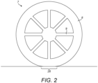
- Figure 2 shows a side view of an example wheel 7 that may be any of the front or rear wheels 2, 3.
- the wheel 7 comprises a tyre 8 and a wheel rim 9 to which the tyre 8 is fitted.
- the wheel rim 9 is configured so that it can be secured to the rest of the vehicle 1.
- the wheels 2, 3 are mounted on hub carriers.
- each wheel rim 9 is mounted on a hub carrier.
- Each wheel can rotate relative to its respective hub carrier about a generally horizontal axis. This rotation axis may be known as the respective rolling axis of the respective wheel 2, 3.
- the wheels rotate about their respective rolling axes as the vehicle moves along a surface such as the ground due to the wheels contacting the ground and supporting the body of the vehicle against the ground.
- Each hub carrier is mounted to the body 6 of the vehicle 1 by a suspension mechanism indicated generally at 10. At least some of the wheels may be steerable wheels.
- the vehicle may comprise a pair of steerable wheels.
- the steerable wheels may be the front wheels 2.
- the suspension mechanisms 10 of the steerable wheels 2 are mounted to the hub carriers in such a way that each hub carrier can rotate about a respective steer axis. This thus causes the rolling axis of the wheel that is being steered to rotate about the steer axis.
- the suspension mechanism 10 may comprise linkages 11 to connect the hub carrier to the vehicle body 6.
- the suspension mechanism 10 may comprise one or more suspension components 12 such as springs and/or dampers.
- the suspension components 12 may provide forces to the linkages 11 to control the motion and/or position of the linkages 11. In this way, the motion and/or position of the wheels 2, 3 relative to the vehicle body 6 can be controlled.
- the vehicle 1 comprises a powertrain shown generally at 13.
- the powertrain 13 may comprise an internal combustion engine 14.
- the powertrain 13 may comprise one or more electric motors 15.
- the powertrain 13 may comprise one or more gearboxes 16 to adjust the rotational speed of the internal combustion engine 14 and/or the electric motor(s) 15.
- the powertrain 13 may be connected to one or more of the wheels 2, 3 by one or more drive shafts 17. In this way the powertrain 13 can drive one or more of the wheels 2, 3.
- the powertrain 13 may be formed of multiple separate units, each unit driving one or more of the wheels 2, 3. For instance, separate electric motors may individually drive the front wheels 2.
- an internal combustion engine 14 may drive the rear wheels 3 optionally with the assistance of one or more electric motors 15. These examples may be combined together. It will be appreciated that there are multiple configurations of powertrain units that may be present in a vehicle 1.
- the vehicle 1 may comprise controls located within the occupant compartment 4 to enable an occupant to control the motion of the vehicle 1.
- One of those controls may be a steering wheel 18.
- the steering attitude of the wheels 2 is controlled by the steering wheel 18.
- the steering wheel 18 may be connected to the steered wheels 2 by a steering mechanism so that when the steering wheel 18 is rotated the steered wheels 2 rotate about their respective steer axis.
- Another of those controls may be a throttle pedal 19.
- the throttle pedal 19 enables an occupant to provide input on the required torque demanded from the powertrain 13. Generally, the further the throttle pedal 19 is depressed then the greater the torque demand from the driver.
- Another of those controls may be a brake pedal 20.
- the brake pedal 20 enables an occupant of to provide input on the braking force required by brakes that are attached to wheels 2, 3.
- the vehicle 1 may comprise a display 21 which provides information to the occupants of the vehicle 1.
- the display 21 may also be referred to as a dashboard.
- the display 21 may display one or more instruments.
- the instruments providing information on the current status of the vehicle. For instance, how fast the vehicle is travelling, what gear the vehicle is in, and the speed of rotation of parts of the powertrain such as the internal combustion engine 14.
- the display 21 may also provide the occupants, and particularly the driver, with information on how to optimally control the vehicle in a given situation. For instance, the display 21 may indicate the optimal moment to change gear.
- the vehicle may comprise a speaker 31.
- the operation of the vehicle is regulated by a Vehicle Control Unit (VCU) 22.
- the VCU 22 comprises a processor 23 and a non-volatile memory 24.
- the VCU 22 may comprise more than one processor 23 and more than one memory 24.
- the memory 24 stores a set of program instructions that are executable by the processor , and reference data such as look-up tables that can be referenced by the processor in response to those instructions.
- the processor 23 may be configured to operate in accordance with a computer program stored in non-transitory form on a machine readable storage medium.
- the computer program may store instructions for causing the processor to perform the operations of the VCU 22 in the manner described herein.
- the VCU 22 may be formed of a number of control units, such an Engine Control Unit, Power Source Control Unit, Gearbox Control Unit, and/or Suspension Control Unit.
- the VCU 22 is connected to various vehicle components to gather data about the operation of those components.
- the VCU 22 is connected to various vehicle components to provide control data to those components. The control data influencing the control of the relevant component.
- the VCU 22 is connected one or more vehicle sensors 25.
- the vehicle sensor(s) 25 each provide vehicle condition data.
- the vehicle condition data that the sensor 25 provides will be dependent on what the sensor 25 is sensing.
- the vehicle sensors may include:
- the VCU 22 controls one or more vehicle dynamics systems within the vehicle.
- the vehicle dynamics systems control elements of the operation of the vehicle.
- the vehicle dynamics systems control the operation of components of the vehicle.
- the vehicle dynamics systems are able to adjust the operation of components of the vehicle so that they operate in a particular way at a particular time.
- Each vehicle dynamics system may operate according to a respective set of predefined rules which define how the components under the control of the particular vehicle dynamics system operate.
- the vehicle dynamics systems may include:
- the VCU 22 may make use of a Kalman filter to undertake its methods.
- the Kalman filter is used to predict the state of the vehicle using data received from the vehicle sensors.
- the VCU 22 controls the vehicle dynamics systems in response to the predicted state of the vehicle.
- the vehicle comprises a road wheel 2, 3.
- the road wheel comprises a tyre sensor 26.
- the tyre sensor 26 is located within the wheel 2, 3.
- Each wheel may have a tyre sensor 26 associated with it as shown in figure 1 .
- the tyre sensor 26 communicates with a tyre sensor receiver 27.
- the tyre sensor receiver 27 communicates wirelessly with the tyre sensor(s) 26.
- the tyre sensor(s) are separate to the vehicle sensors.
- the tyre sensor 26 analyses the motion of the wheel to generate tyre operation data associated with the wheel.
- the tyre sensor 26 may analyse the relative motion of the tyre 8 relative to the wheel rim 9 to generate the tyre operational data.
- the tyre sensor 26 may analyse the interior conditions of the wheel (i.e. the region enclosed by the tyre and the wheel rim) to generate tyre operation data.
- the tyre sensor 26 may analyse a contact patch 28 associated with the tyre 8 to generate tyre operation data.
- the contact patch 28 being the portion of the tyre 28 that is in contact with a running surface of the vehicle 1.
- the tyre sensor 26 may be encoded with a tyre identifier which is provided as tyre operational data.
- the tyre sensor receiver 27 may process the tyre operational data received from the tyre sensor 26 to translate the data into a form that is readable by the vehicle's systems, such as the VCU 22.
- the tyre operation data that the tyre sensor 26 outputs may comprise one or more of the following types of tyre operation data:
- the tyre operational data can be used by the VCU 22 to improve the control of one or more vehicle dynamics systems within the vehicle 1.
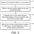
- Such an improved method for adjusting one or more vehicle dynamics systems of the vehicle 1 that may be implemented by a VCU 22 will now be explained with reference to figure 3.
- Figure 3 shows a flowchart of such an improved method.
- tyre operation data is received from the tyre sensor.
- the tyre operation data is received by the VCU 22 via the tyre sensor receiver 27.
- the tyre sensor receiver 27 may process the tyre operation data sent by the tyre sensor to put the tyre operation data in a form that is suitable for the VCU 22 to operate on.
- the tyre operation data is sent periodically to the VCU 22.
- the VCU 22 receives updated tyre operation data over time.
- the frequency of the sending of the tyre operation data may be such that it is in effect streamed to the VCU 22. I.e. the period between each update is short.
- the tyre operation data that is received by the VCU 22 may be any of the types of tyre operation data described herein. Some types of tyre operation data may be more static than others which are more variable. In this case some of the tyre operation data may be provided to the VCU 22 with a higher frequency than other types of tyre operation data. For instance, the tyre identifier may only need to be sent when the vehicle starts up, whereas the contact patch longitudinal load may be streamed to the VCU 22.
- vehicle condition data is received from at least one vehicle sensor.
- the VCU 22 is connected to one or more vehicle sensors to each provide vehicle condition data.
- the vehicle condition data is sent periodically to the VCU 22.
- the VCU 22 receives updated vehicle condition data over time.
- the frequency of the sending of the vehicle condition data by a particular sensor may be such that it is in effect streamed to the VCU 22. I.e. the period between each update is short.
- the vehicle condition data that is received by the VCU 22 may be any of the types of vehicle condition data described herein. Some types of vehicle condition data may be more static than others which are more variable. In this case some of the vehicle condition data may be provided to the VCU 22 with a higher frequency than other types of vehicle condition data. For instance, the current gear selected by the gearbox may only need to be sent when the vehicle changes gear, whereas the engine revolution speed may be streamed to the VCU 22.
- one or more vehicle dynamics parameters are calculated based on the vehicle condition data and the tyre operation data.
- Vehicle dynamics parameters describe the current motion state of the vehicle.
- One or more vehicle dynamics parameters may be calculated based on the vehicle condition data, historic vehicle condition data and the tyre operation data.
- Historic vehicle condition data being stored vehicle condition data that was generated at least one previous point in time.
- the vehicle dynamics parameters can be calculated based on a model of the vehicle.
- the model of the vehicle describes the operation of the vehicle components over the operational range of the vehicle components.
- the model may have replaceable elements depending on the components that are fitted to the vehicle 1. For instance, a tyre element of the model may be selected based on the tyre identifier. The tyre identifier being provided as part of the tyre operation data.
- the model of the vehicle permits calculation of the current motion state of the vehicle by using the tyre operation data and vehicle condition data as inputs to predict the current motion state of the vehicle 1.
- the vehicle dynamics parameters that are calculated can be used to adjust one or more vehicle dynamics systems to enable optimal control of the vehicle 1 at a given moment.
- the vehicle dynamics parameters that are calculated may comprise one or more of the following:
- one or more vehicle dynamics systems are adjusted in response to the calculated one or more vehicle dynamics parameters.
- the one or more vehicle dynamics systems may be adjusted in response to historic vehicle dynamics parameters.
- Historic vehicle dynamics parameters being stored vehicle dynamics parameters that were generated at least one previous point in time.
- the adjustment of the vehicle dynamics systems can be more accurately controlled because the VCU 22 obtains data from the tyre sensors together with the vehicle sensors and uses the combination of this data which has produced the vehicle dynamics parameters to then control the vehicle dynamics systems.
- the VCU 22 may adjust one or more of the vehicle ride height system, stability control system, torque vectoring control system, active aero control system, and traction control system based on the calculated one or more vehicle dynamics parameters.
- the vehicle ride height system may be adjusted to change a ride height of the vehicle based on the calculated aerodynamic load. For instance, if a high aerodynamic load is calculated then the ride height of the vehicle may be corrected.
- a high aerodynamic load may mean that the suspension is compressed which would lead to a reduction in the ride height of the vehicle 1. Therefore, the vehicle ride height system may be adjusted to increase the ride height of the vehicle.
- a high aerodynamic load may mean that is advantageous to lower the ride height of the vehicle.
- a high aerodynamic load may be determined by the aerodynamic load being above a threshold aerodynamic load. Therefore, the vehicle ride height system may be adjusted to lower the ride height of the vehicle. If a low aerodynamic load is calculated then the ride height of the vehicle may be corrected.
- a low aerodynamic load may mean that the suspension is extended which would lead to an increase in the ride height of the vehicle 1. Therefore, the vehicle ride height system may be adjusted to lower the ride height of the vehicle.
- a low aerodynamic load may mean that is advantageous to raise the ride height of the vehicle.
- a low aerodynamic load may be determined by the aerodynamic load being below a threshold aerodynamic load. Therefore, the vehicle ride height system may be adjusted to raise the ride height of the vehicle.
- the stability control system may be adjusted to counter movement of the body of the vehicle 1. For instance, the stability control system may be adjusted when a non-zero sideslip angle is calculated to counter vehicle roll. The stability control system may be adjusted to cause at least some of the controllable linkages in the suspension system to increase the amount of resistance provided to the suspension system to counter vehicle roll.
- the torque vectoring control system may be adjusted in response to one or more of the calculated maximum road friction coefficient, current vehicle speed and sideslip angle.
- the torque vectoring control system may be adjusted to cause a steering effect using torque vectoring.
- the torque vectoring control system may be adjusted to cause a steering effect using torque vectoring to counter a sideslip angle. For instance, the torque vectoring control system may be adjusted to steer against the sideslip angle to reduce the sideslip angle.
- the torque vectoring control system may be adjusted to based on the current vehicle speed. For instance, the torque vectoring control system may be adjusted to provide less torque vectoring at high speed and more torque vectoring at low speeds.
- the torque vectoring control system may be adjusted to based on the calculated maximum road friction coefficient. For instance, the torque vectoring control system may be adjusted to provide less torque vectoring if the calculated maximum road friction coefficient is low and more torque vectoring if the calculated maximum road friction coefficient is high.
- the torque vectoring control system may be adjusted based on a combination of these factors.
- the active aero control system may be adjusted based on the aerodynamic load and/or current vehicle speed.
- the active aero control system may be adjusted to change downforce provided by active aerodynamic devices 29, 30 based on the aerodynamic load and/or current vehicle speed.
- the active aero control system may be adjusted to reduce downforce provided by active aerodynamic devices 29, 30 based on the aerodynamic load and/or current vehicle speed. For instance, the active aero control system may be adjusted to reduce downforce provided by active aerodynamic devices 29, 30 based on the current vehicle speed being high.
- the downforce provided by active aerodynamic device 29, 30 may be reduced once the current vehicle speed is above a threshold vehicle speed.
- the active aero control system may be adjusted to reduce downforce provided by active aerodynamic devices 29, 30 based on the aerodynamic load being high.
- the downforce provided by active aerodynamic device 29, 30 may be reduced once the aerodynamic load is above a threshold aerodynamic load. Both of these options may help to reduce drag at high speed.
- the traction control system may be adjusted based on the maximum road friction coefficient and/or current vehicle speed.
- a maximum tyre grip level may be calculated based on the maximum road friction coefficient.
- a respective maximum tyre grip level may be calculated for each wheel.
- the traction control system may be adjusted based on the maximum road friction coefficient and/or current vehicle speed to control a torque provided to a wheel to be at or below the maximum tyre grip level.
- Tyre parameter accuracy is fundamental in determining the contact forces.
- the maximum tyre grip estimation may be accomplished by extending a nonlinear vehicle model in the time update of the unscented Kalman filter with an additional state-space equation with a new variable.
- the new variable may be an estimated parameter, which is described by a random walk model.
- the random walk model is a stationary process only driven by corresponding process noise.
- the maximum tyre grip level may be integrated in to a tyre model as a scaling parameter of the maximum longitudinal and lateral forces on the wheel ij in pure longitudinal and lateral slip conditions:
- D xij F zij p Dx 1 + p Dx 2 df zij 1 ⁇ p Dx 3 ⁇ xij 2 ⁇ ⁇ x ⁇ max
- D yij F zij p Dy 1 + p Dy 2 df zij 1 ⁇ p Dy 3 ⁇ yij 2 ⁇ ⁇ y ⁇ max
- df zij is the normalised vertical load of the wheel ij ;
- ⁇ xij and ⁇ yij are linear functions of the camber angle of the respective wheel;
- ⁇ ⁇ x and ⁇ ⁇ y are the scale factors of the friction coefficient in pure longitudinal and lateral slip conditions.
- ⁇ max The purpose of the ⁇ max estimation is to enhance the estimation of the main filter outputs, e.g. vehicle speed, sideslip angle, and lateral tyre forces, rather than achieving an accurate friction estimation.
- ⁇ max constitutes an additional degree of freedom, which increases the vehicle model robustness by scaling the tyre-road friction coefficient in a Pacejka tyre model formulation.
- the system and methods described herein use data provided from vehicle sensors together with data provided from tyre sensors to provide a better estimate of the current state of the vehicle. This better estimate permits more accurate control of various vehicle dynamics system to achieve closer to optimum performance of the vehicle 1.
- vehicle dynamics controllers e.g. the VCU.
- One or more vehicle dynamics systems of the vehicle can then be adjusted through the inclusion of the vertical and longitudinal tyre contact force signals, obtained through smart tyres that have the tyre sensors, to an unscented Kalman filter for vehicle speed and sideslip angle estimation, based on a nonlinear vehicle dynamics model. This significantly enhances the robustness and adaptability of the estimations for typical variations of vehicle and tyre parameters.
Landscapes
- Engineering & Computer Science (AREA)
- Mechanical Engineering (AREA)
- Transportation (AREA)
- Automation & Control Theory (AREA)
- Physics & Mathematics (AREA)
- Mathematical Physics (AREA)
- Chemical & Material Sciences (AREA)
- Combustion & Propulsion (AREA)
- Fluid Mechanics (AREA)
- Vehicle Body Suspensions (AREA)
- Measuring Fluid Pressure (AREA)
Applications Claiming Priority (1)
| Application Number | Priority Date | Filing Date | Title |
|---|---|---|---|
| GBGB2215775.4A GB202215775D0 (en) | 2022-10-25 | 2022-10-25 | Vehicle dynamics system adjustment |
Publications (2)
| Publication Number | Publication Date |
|---|---|
| EP4360921A2 true EP4360921A2 (fr) | 2024-05-01 |
| EP4360921A3 EP4360921A3 (fr) | 2024-07-24 |
Family
ID=84818539
Family Applications (1)
| Application Number | Title | Priority Date | Filing Date |
|---|---|---|---|
| EP23205850.3A Pending EP4360921A3 (fr) | 2022-10-25 | 2023-10-25 | Réglage de système de dynamique de marche de véhicule |
Country Status (3)
| Country | Link |
|---|---|
| US (1) | US12528452B2 (fr) |
| EP (1) | EP4360921A3 (fr) |
| GB (1) | GB202215775D0 (fr) |
Families Citing this family (4)
| Publication number | Priority date | Publication date | Assignee | Title |
|---|---|---|---|---|
| DE102023106353A1 (de) * | 2023-03-14 | 2024-09-19 | Dr. Ing. H.C. F. Porsche Aktiengesellschaft | Verfahren zur Regelung eines aktiven Fahrwerks |
| US12319105B1 (en) * | 2023-08-01 | 2025-06-03 | Gravic, Inc. | Method and apparatus to dynamically increase tire traction in a vehicle by applying one or more controlled downward directed impulses between a body of the vehicle and a wheel of a vehicle |
| KR20250024653A (ko) * | 2023-08-11 | 2025-02-19 | 현대자동차주식회사 | 타이어 규격에 기초한 차량의 제어 시스템 및 제어 방법 |
| WO2026002948A1 (fr) * | 2024-06-25 | 2026-01-02 | McMurtry Automotive Limited | Système de reglage de hauteur de conduite |
Citations (2)
| Publication number | Priority date | Publication date | Assignee | Title |
|---|---|---|---|---|
| US20170080770A1 (en) * | 2015-09-17 | 2017-03-23 | GM Global Technology Operations LLC | Vehicle ride-height determination for control of vehicle aerodynamics |
| US20170100980A1 (en) * | 2015-10-07 | 2017-04-13 | Toyota Jidosha Kabushiki Kaisha | Suspension control device for vehicle |
Family Cites Families (13)
| Publication number | Priority date | Publication date | Assignee | Title |
|---|---|---|---|---|
| JP3258476B2 (ja) | 1993-12-24 | 2002-02-18 | アイシン精機株式会社 | 車両走行路面の最大摩擦係数推定装置 |
| US7676307B2 (en) | 2001-11-05 | 2010-03-09 | Ford Global Technologies | System and method for controlling a safety system of a vehicle in response to conditions sensed by tire sensors related applications |
| JP2007532371A (ja) * | 2004-03-23 | 2007-11-15 | ケルシ・ヘイズ、カムパニ | 車両転覆軽減の方法および装置 |
| US7983801B2 (en) | 2005-02-22 | 2011-07-19 | Kelsey-Hayes Company | Vehicle stability control utilizing static tire data |
| WO2010117793A2 (fr) | 2009-03-30 | 2010-10-14 | Walter Joel A | Appareil et procédé pour déterminer des forces agissant sur un véhicule dans une soufflerie |
| US9222854B2 (en) | 2013-03-12 | 2015-12-29 | The Goodyear Tire & Rubber Company | Vehicle dynamic load estimation system and method |
| WO2015153811A1 (fr) | 2014-04-02 | 2015-10-08 | Levant Power Corporation | Système de suspension de sécurité active |
| US9937908B2 (en) * | 2015-09-17 | 2018-04-10 | GM Global Technology Operations LLC | Vehicle with model-based control of an active aerodynamic element |
| US10821981B1 (en) | 2017-10-18 | 2020-11-03 | Zoox, Inc. | Independent control of vehicle wheels |
| DE102018212629A1 (de) | 2018-07-27 | 2020-01-30 | Continental Teves Ag & Co. Ohg | Verfahren zur Bestimmung von Fahrbahnzuständen |
| DE102019213911A1 (de) | 2019-09-12 | 2021-03-18 | Thyssenkrupp Ag | Vorrichtung und Verfahren zum Schätzen eines Straßenreibungskoeffizienten |
| US20210139028A1 (en) | 2019-11-13 | 2021-05-13 | Sf Motors, Inc. | Fuzzy logic based and machine learning enhanced vehicle dynamics determination |
| WO2022108603A1 (fr) | 2020-11-23 | 2022-05-27 | Volvo Truck Corporation | Système et procédé permettant l'optimisation de pièces de contact de pneu |
-
2022
- 2022-10-25 GB GBGB2215775.4A patent/GB202215775D0/en active Pending
-
2023
- 2023-10-24 US US18/383,446 patent/US12528452B2/en active Active
- 2023-10-25 EP EP23205850.3A patent/EP4360921A3/fr active Pending
Patent Citations (2)
| Publication number | Priority date | Publication date | Assignee | Title |
|---|---|---|---|---|
| US20170080770A1 (en) * | 2015-09-17 | 2017-03-23 | GM Global Technology Operations LLC | Vehicle ride-height determination for control of vehicle aerodynamics |
| US20170100980A1 (en) * | 2015-10-07 | 2017-04-13 | Toyota Jidosha Kabushiki Kaisha | Suspension control device for vehicle |
Also Published As
| Publication number | Publication date |
|---|---|
| US20240132053A1 (en) | 2024-04-25 |
| GB202215775D0 (en) | 2022-12-07 |
| EP4360921A3 (fr) | 2024-07-24 |
| US12528452B2 (en) | 2026-01-20 |
| US20240227781A9 (en) | 2024-07-11 |
Similar Documents
| Publication | Publication Date | Title |
|---|---|---|
| EP4360921A2 (fr) | Réglage de système de dynamique de marche de véhicule | |
| EP1632382B1 (fr) | Système de stabilisation d'un véhicule automobile avec compensation de la résistance à l'avancement | |
| US8718872B2 (en) | Vehicle attitude controller | |
| US8160795B2 (en) | Drive power control apparatus and method for vehicle | |
| JP3096476B2 (ja) | 原動機付車両のための駆動装置 | |
| JP4285343B2 (ja) | 車輌のロール剛性制御装置 | |
| US20220396112A1 (en) | Method to control the active shock absorbers of a road vehicle featuring the lowering of the centre of gravity | |
| US20190263458A1 (en) | Methods and systems for active aerodynamic balance | |
| EP4360978B1 (fr) | Assistance à la commande d'un véhicule | |
| US11491970B2 (en) | Architecture and methodology for integrated wheel and body dynamic controls with standard stability features | |
| US10625777B2 (en) | Attitude control system | |
| CN112406854A (zh) | 轮毂电机驱动越野车侧倾稳定性控制方法 | |
| CN112706756B (zh) | 轮毂电机驱动越野车横摆稳定性控制方法 | |
| US12145413B2 (en) | Suspension control device, vehicle, and suspension control method | |
| US11148498B2 (en) | Method for controlling wheel axle suspension of a vehicle | |
| JP2005184971A (ja) | 電動車両のモータ出力制御装置 | |
| US20070021887A1 (en) | Method and system for controlling a yawing moment actuator in a motor vehicle | |
| US20210155211A1 (en) | Braking force control system | |
| US12269461B2 (en) | Vehicle behavior control method, a computing system, and a vehicle supporting the same | |
| EP4361750B1 (fr) | Prédiction de durée de vie de composant | |
| JP4639914B2 (ja) | 車両挙動制御装置 | |
| JP2008144788A (ja) | 車両の駆動力制御装置 | |
| US20260028071A1 (en) | Determining a desired lateral acceleration for a vehicle | |
| EP4204283B1 (fr) | Système et méthode de réduction de vibrations dans la cabine de véhicule utilitaire | |
| US20250222933A1 (en) | Control device for vehicle |
Legal Events
| Date | Code | Title | Description |
|---|---|---|---|
| PUAI | Public reference made under article 153(3) epc to a published international application that has entered the european phase |
Free format text: ORIGINAL CODE: 0009012 |
|
| STAA | Information on the status of an ep patent application or granted ep patent |
Free format text: STATUS: THE APPLICATION HAS BEEN PUBLISHED |
|
| AK | Designated contracting states |
Kind code of ref document: A2 Designated state(s): AL AT BE BG CH CY CZ DE DK EE ES FI FR GB GR HR HU IE IS IT LI LT LU LV MC ME MK MT NL NO PL PT RO RS SE SI SK SM TR |
|
| PUAL | Search report despatched |
Free format text: ORIGINAL CODE: 0009013 |
|
| AK | Designated contracting states |
Kind code of ref document: A3 Designated state(s): AL AT BE BG CH CY CZ DE DK EE ES FI FR GB GR HR HU IE IS IT LI LT LU LV MC ME MK MT NL NO PL PT RO RS SE SI SK SM TR |
|
| RIC1 | Information provided on ipc code assigned before grant |
Ipc: B62D 37/02 20060101ALI20240617BHEP Ipc: B60W 40/068 20120101ALI20240617BHEP Ipc: B60T 8/1763 20060101ALI20240617BHEP Ipc: B60G 17/016 20060101AFI20240617BHEP |
|
| STAA | Information on the status of an ep patent application or granted ep patent |
Free format text: STATUS: REQUEST FOR EXAMINATION WAS MADE |
|
| 17P | Request for examination filed |
Effective date: 20250124 |
|
| STAA | Information on the status of an ep patent application or granted ep patent |
Free format text: STATUS: EXAMINATION IS IN PROGRESS |
|
| 17Q | First examination report despatched |
Effective date: 20260202 |