EP4360954A1 - Groupe de modules de phare de véhicule, phare de véhicule et véhicule - Google Patents
Groupe de modules de phare de véhicule, phare de véhicule et véhicule Download PDFInfo
- Publication number
- EP4360954A1 EP4360954A1 EP22891734.0A EP22891734A EP4360954A1 EP 4360954 A1 EP4360954 A1 EP 4360954A1 EP 22891734 A EP22891734 A EP 22891734A EP 4360954 A1 EP4360954 A1 EP 4360954A1
- Authority
- EP
- European Patent Office
- Prior art keywords
- low
- modules
- module
- vehicle lamp
- vehicle
- Prior art date
- Legal status (The legal status is an assumption and is not a legal conclusion. Google has not performed a legal analysis and makes no representation as to the accuracy of the status listed.)
- Pending
Links
- 239000011159 matrix material Substances 0.000 claims description 8
- 238000005286 illumination Methods 0.000 abstract description 21
- 238000010586 diagram Methods 0.000 description 48
- 238000000034 method Methods 0.000 description 9
- 230000000694 effects Effects 0.000 description 6
- 230000001788 irregular Effects 0.000 description 5
- 238000005516 engineering process Methods 0.000 description 3
- 230000009286 beneficial effect Effects 0.000 description 1
- 238000004891 communication Methods 0.000 description 1
- 238000012986 modification Methods 0.000 description 1
- 230000004048 modification Effects 0.000 description 1
Images




Classifications
-
- F—MECHANICAL ENGINEERING; LIGHTING; HEATING; WEAPONS; BLASTING
- F21—LIGHTING
- F21S—NON-PORTABLE LIGHTING DEVICES; SYSTEMS THEREOF; VEHICLE LIGHTING DEVICES SPECIALLY ADAPTED FOR VEHICLE EXTERIORS
- F21S41/00—Illuminating devices specially adapted for vehicle exteriors, e.g. headlamps
-
- F—MECHANICAL ENGINEERING; LIGHTING; HEATING; WEAPONS; BLASTING
- F21—LIGHTING
- F21S—NON-PORTABLE LIGHTING DEVICES; SYSTEMS THEREOF; VEHICLE LIGHTING DEVICES SPECIALLY ADAPTED FOR VEHICLE EXTERIORS
- F21S41/00—Illuminating devices specially adapted for vehicle exteriors, e.g. headlamps
- F21S41/10—Illuminating devices specially adapted for vehicle exteriors, e.g. headlamps characterised by the light source
- F21S41/14—Illuminating devices specially adapted for vehicle exteriors, e.g. headlamps characterised by the light source characterised by the type of light source
- F21S41/141—Light emitting diodes [LED]
- F21S41/147—Light emitting diodes [LED] the main emission direction of the LED being angled to the optical axis of the illuminating device
-
- B—PERFORMING OPERATIONS; TRANSPORTING
- B60—VEHICLES IN GENERAL
- B60Q—ARRANGEMENT OF SIGNALLING OR LIGHTING DEVICES, THE MOUNTING OR SUPPORTING THEREOF OR CIRCUITS THEREFOR, FOR VEHICLES IN GENERAL
- B60Q1/00—Arrangement of optical signalling or lighting devices, the mounting or supporting thereof or circuits therefor
- B60Q1/0029—Spatial arrangement
- B60Q1/0041—Spatial arrangement of several lamps in relation to each other
-
- F—MECHANICAL ENGINEERING; LIGHTING; HEATING; WEAPONS; BLASTING
- F21—LIGHTING
- F21S—NON-PORTABLE LIGHTING DEVICES; SYSTEMS THEREOF; VEHICLE LIGHTING DEVICES SPECIALLY ADAPTED FOR VEHICLE EXTERIORS
- F21S41/00—Illuminating devices specially adapted for vehicle exteriors, e.g. headlamps
- F21S41/20—Illuminating devices specially adapted for vehicle exteriors, e.g. headlamps characterised by refractors, transparent cover plates, light guides or filters
- F21S41/25—Projection lenses
-
- F—MECHANICAL ENGINEERING; LIGHTING; HEATING; WEAPONS; BLASTING
- F21—LIGHTING
- F21S—NON-PORTABLE LIGHTING DEVICES; SYSTEMS THEREOF; VEHICLE LIGHTING DEVICES SPECIALLY ADAPTED FOR VEHICLE EXTERIORS
- F21S41/00—Illuminating devices specially adapted for vehicle exteriors, e.g. headlamps
- F21S41/30—Illuminating devices specially adapted for vehicle exteriors, e.g. headlamps characterised by reflectors
-
- F—MECHANICAL ENGINEERING; LIGHTING; HEATING; WEAPONS; BLASTING
- F21—LIGHTING
- F21S—NON-PORTABLE LIGHTING DEVICES; SYSTEMS THEREOF; VEHICLE LIGHTING DEVICES SPECIALLY ADAPTED FOR VEHICLE EXTERIORS
- F21S41/00—Illuminating devices specially adapted for vehicle exteriors, e.g. headlamps
- F21S41/60—Illuminating devices specially adapted for vehicle exteriors, e.g. headlamps characterised by a variable light distribution
- F21S41/65—Illuminating devices specially adapted for vehicle exteriors, e.g. headlamps characterised by a variable light distribution by acting on light sources
- F21S41/663—Illuminating devices specially adapted for vehicle exteriors, e.g. headlamps characterised by a variable light distribution by acting on light sources by switching light sources
-
- F—MECHANICAL ENGINEERING; LIGHTING; HEATING; WEAPONS; BLASTING
- F21—LIGHTING
- F21S—NON-PORTABLE LIGHTING DEVICES; SYSTEMS THEREOF; VEHICLE LIGHTING DEVICES SPECIALLY ADAPTED FOR VEHICLE EXTERIORS
- F21S43/00—Signalling devices specially adapted for vehicle exteriors, e.g. brake lamps, direction indicator lights or reversing lights
-
- F—MECHANICAL ENGINEERING; LIGHTING; HEATING; WEAPONS; BLASTING
- F21—LIGHTING
- F21S—NON-PORTABLE LIGHTING DEVICES; SYSTEMS THEREOF; VEHICLE LIGHTING DEVICES SPECIALLY ADAPTED FOR VEHICLE EXTERIORS
- F21S45/00—Arrangements within vehicle lighting devices specially adapted for vehicle exteriors, for purposes other than emission or distribution of light
- F21S45/40—Cooling of lighting devices
- F21S45/47—Passive cooling, e.g. using fins, thermal conductive elements or openings
-
- F—MECHANICAL ENGINEERING; LIGHTING; HEATING; WEAPONS; BLASTING
- F21—LIGHTING
- F21V—FUNCTIONAL FEATURES OR DETAILS OF LIGHTING DEVICES OR SYSTEMS THEREOF; STRUCTURAL COMBINATIONS OF LIGHTING DEVICES WITH OTHER ARTICLES, NOT OTHERWISE PROVIDED FOR
- F21V19/00—Fastening of light sources or lamp holders
-
- F—MECHANICAL ENGINEERING; LIGHTING; HEATING; WEAPONS; BLASTING
- F21—LIGHTING
- F21W—INDEXING SCHEME ASSOCIATED WITH SUBCLASSES F21K, F21L, F21S and F21V, RELATING TO USES OR APPLICATIONS OF LIGHTING DEVICES OR SYSTEMS
- F21W2102/00—Exterior vehicle lighting devices for illuminating purposes
- F21W2102/10—Arrangement or contour of the emitted light
- F21W2102/13—Arrangement or contour of the emitted light for high-beam region or low-beam region
-
- F—MECHANICAL ENGINEERING; LIGHTING; HEATING; WEAPONS; BLASTING
- F21—LIGHTING
- F21W—INDEXING SCHEME ASSOCIATED WITH SUBCLASSES F21K, F21L, F21S and F21V, RELATING TO USES OR APPLICATIONS OF LIGHTING DEVICES OR SYSTEMS
- F21W2102/00—Exterior vehicle lighting devices for illuminating purposes
- F21W2102/10—Arrangement or contour of the emitted light
- F21W2102/13—Arrangement or contour of the emitted light for high-beam region or low-beam region
- F21W2102/135—Arrangement or contour of the emitted light for high-beam region or low-beam region the light having cut-off lines, i.e. clear borderlines between emitted regions and dark regions
-
- F—MECHANICAL ENGINEERING; LIGHTING; HEATING; WEAPONS; BLASTING
- F21—LIGHTING
- F21W—INDEXING SCHEME ASSOCIATED WITH SUBCLASSES F21K, F21L, F21S and F21V, RELATING TO USES OR APPLICATIONS OF LIGHTING DEVICES OR SYSTEMS
- F21W2103/00—Exterior vehicle lighting devices for signalling purposes
-
- F—MECHANICAL ENGINEERING; LIGHTING; HEATING; WEAPONS; BLASTING
- F21—LIGHTING
- F21W—INDEXING SCHEME ASSOCIATED WITH SUBCLASSES F21K, F21L, F21S and F21V, RELATING TO USES OR APPLICATIONS OF LIGHTING DEVICES OR SYSTEMS
- F21W2105/00—Combinations of lighting devices covered by codes F21W2102/00 – F21W2104/00
-
- Y—GENERAL TAGGING OF NEW TECHNOLOGICAL DEVELOPMENTS; GENERAL TAGGING OF CROSS-SECTIONAL TECHNOLOGIES SPANNING OVER SEVERAL SECTIONS OF THE IPC; TECHNICAL SUBJECTS COVERED BY FORMER USPC CROSS-REFERENCE ART COLLECTIONS [XRACs] AND DIGESTS
- Y02—TECHNOLOGIES OR APPLICATIONS FOR MITIGATION OR ADAPTATION AGAINST CLIMATE CHANGE
- Y02B—CLIMATE CHANGE MITIGATION TECHNOLOGIES RELATED TO BUILDINGS, e.g. HOUSING, HOUSE APPLIANCES OR RELATED END-USER APPLICATIONS
- Y02B20/00—Energy efficient lighting technologies, e.g. halogen lamps or gas discharge lamps
- Y02B20/40—Control techniques providing energy savings, e.g. smart controller or presence detection
Definitions
- the present disclosure relates to the field of vehicle lighting technology, and particularly, to a vehicle lamp module group, a vehicle lamp, and a vehicle.
- the lighting effect of a vehicle lamp is more diversified and more beautiful, which prompts a user to have a higher requirement for the lighting effect of the vehicle lamp.
- the users expect that their vehicle lamp can have a lighting effect different from that of other users without affecting the normal use of the vehicle lamp, thereby realizing personalized customization.
- the existing vehicle lamp has a relatively simple lighting effect, and the aesthetics needs to be improved.
- Embodiments of the present disclosure aim to provide a vehicle lamp module group, a vehicle lamp and a vehicle, such that a user can select different lighting forms according to the preference to make the vehicle lamp present different appearances.
- Embodiments of the present disclosure are implemented as follows.
- the present disclosure provides a vehicle lamp module group.
- the vehicle lamp module group includes: a plurality of low-beam modules; and a plurality of high-beam modules, the low-beam modules and the high-beam modules being arranged in a preset manner, where projected light of at least two low-beam modules can jointly form a low-beam light shape, and projected light of at least two high-beam modules can jointly form a high-beam light shape.
- the vehicle lamp module group further includes: a plurality of signal lamp modules, where the signal lamp modules, the low-beam modules and the high-beam modules are arranged in a preset manner.
- the vehicle lamp module group includes a low-beam unit and a high-beam unit
- the low-beam unit includes at least one low-beam module and a housing accommodating the low-beam module
- the high-beam unit includes at least one high-beam module and a housing accommodating the high-beam module
- the low-beam unit and the high-beam unit are arranged in a preset manner.
- the low-beam units include a low-beam unit having one low-beam module and a low-beam light unit having two interconnected low-beam modules, and the high-beam unit includes three interconnected high-beam modules.
- each column of units constitute a column of vehicle lamp units, or each row of units constitute a row of vehicle lamp units.
- a first row of the vehicle lamp units include two low-beam units having one low-beam module, two low-beam units having two interconnected low-beam modules and one high-beam unit having three interconnected high-beam modules, and a second row of the vehicle lamp units include two low-beam units having one low-beam module, one low-beam unit having two interconnected low-beam modules and one high-beam unit having three interconnected high-beam modules.
- a plurality of the low-beam modules and a plurality of the high-beam modules are arranged in a matrix, each column of modules or each row of modules constitutes one module unit, and the module unit includes a housing accommodating each module.
- one of the low-beam modules and one of the signal lamp modules are combined to form one module unit; and/or, one of the high-beam modules and one of the signal lamp modules are combined to form one module unit; and the module unit includes a housing accommodating modules, and a plurality of the module units are arranged in a preset manner.
- At least one of the low-beam module and the high-beam module includes: a lens, a reflector, a light source, and a circuit board, where the light source is arranged on the circuit board, the light source is positioned below the reflector, the lens is arranged in front of the reflector, and light of the light source enters from one end of the lens and exits from the other end of the lens after being reflected by the reflector.
- At least one of the low-beam module and the high-beam module further includes a radiator connected to the circuit board.
- the radiator is positioned on a surface of the circuit board away from the light source, and the radiator is bolted to the circuit board.
- the present disclosure provides a vehicle lamp, including a control module and the vehicle lamp module group provided in any embodiment according to the first aspect of the present disclosure, where the control module is connected to the vehicle lamp module group, and the control module can control on/off of each module.
- the present disclosure provides a vehicle, including a vehicle body, a user terminal and at least one vehicle lamp provided in the second aspect of the present disclosure; where the vehicle lamp is arranged on the vehicle body, and the user terminal is arranged on the vehicle body and connected to the vehicle lamp.
- control module of the vehicle lamp is provided with a plurality of lighting modes
- the user terminal is connected to the control module
- the user terminal sends a control instruction to the control module to select the lighting mode
- the control module controls on/off of each module on the vehicle lamp according to the control instruction.
- At least one of the user terminal and the control module is integrated into a central control room of the vehicle body.
- the vehicle lamp module group includes a plurality of low-beam modules and a plurality of high-beam modules, the low-beam modules and the high-beam modules may be arranged according to a certain rule or arranged irregularly, such that projected light of at least two low-beam modules can jointly form a low-beam light shape, and projected light of at least two high-beam modules can jointly form a high-beam light shape; a user may select a corresponding number of low-beam modules and a corresponding number of high-beam modules to realize high-beam and low-beam illumination; in addition, according to personal preferences, the user may select to present different lighting forms of the low-beam modules, the high-beam modules and signal lamp modules, so as to make his/her vehicle lamp present different appearance styles.
- horizontal merely means that the direction is more horizontal than “vertical” and does not mean that the structure must be perfectly horizontal, but may be slightly inclined.
- an orientation or positional relationship indicated by terms “inner”, “outer”, “left”, “right”, “upper”, “lower”, or the like is an orientation or positional relationship based on the accompanying drawings, or an orientation or positional relationship that the product of the present disclosure is usually placed when in use. These terms are merely used to facilitate and simplify description of the present disclosure, instead of indicating or implying that a mentioned apparatus or element must have a specific orientation or be constructed and operated in a specific orientation, and therefore the terms cannot be construed as a limitation on the present disclosure.
- FIG. 1 is a structural schematic diagram of a vehicle 1 according to an embodiment of the present disclosure.
- the vehicle 1 includes a vehicle body 11, at least one vehicle lamp 12, and a user terminal 13, where the vehicle lamp 12 is arranged on the vehicle body 11.
- the user terminal 13 is arranged in the vehicle body 11 and electrically connected to the vehicle lamp 12.
- the user terminal 13 may be integrated into a central control room of the vehicle body 11.
- the vehicle 1 may be a human-driven automobile or an autonomous driving vehicle of various levels.
- the vehicle lamp 12 may include one or more of a headlight, a brake light, a turn signal light, a position light or a daytime running light.
- the vehicle lamp 12 When the vehicle lamp 12 is a headlight, the vehicle lamp 12 may be mounted at two sides of the head of the vehicle body 11 for lighting during night driving and urban road driving; when the vehicle lamp 12 is a brake lamp, the vehicle lamp 12 may be mounted at the rear of the vehicle body 11 to indicate the steering, deceleration or stopping of the driving vehicle 1, providing a clear driving indication to the vehicles behind; and when the vehicle lamp 12 is a turn signal light, the vehicle lamp 12 may be mounted at the front, rear, and side of the vehicle body 11 to indicate the steering of the vehicle 1.
- the vehicle lamp 12 When the vehicle lamp 12 is a position lamp, the vehicle lamp 12 may be mounted at the front and rear of the vehicle 1 for displaying a position of the vehicle 1 after the vehicle is started. For example, when the vehicle breaks down and is parked at the roadside, the position lamp of the vehicle needs to be turned on to inform the coming and going vehicle to pay attention; and it is also for indicating the presence of the driving vehicle and the width of the vehicle body when special vehicles such as police vehicles perform tasks at special time; and when the vehicle lamp 12 is a daytime running light, the vehicle lamp 12 may be mounted at two sides of a front end of the vehicle 1, for prompting the presence of the vehicle 1 to the front in the daytime.
- FIG. 2 is a structural schematic diagram of a vehicle lamp 12 according to an embodiment of the present disclosure.
- the vehicle lamp 12 includes a control module 121 and a vehicle lamp module group 100, where the control module 121 is connected to the vehicle lamp module group 100, and the control module 121 can control on/off of each module.
- the control module 121 is provided with several lighting modes presented by different lighting forms of light-emitting units in the vehicle lamp module group 100, a user can send an instruction to the control module 121 through the user terminal 13 to select a corresponding lighting mode, and the control module 121 controls on/off of the corresponding modules in the vehicle lamp module group 100 on the vehicle lamp 12 according to the instruction.
- both the user terminal 13 and the control module 121 may be integrated into a central control room of the vehicle body 11, and the user can select a preferred lighting mode on the central control display screen, so that the vehicle lamp 12 can present different vehicle lamp lighting configurations while meeting the requirement of road illumination, and different lighting effects are displayed on the central control display screen for the user to select.
- the user terminal 13 is provided with an APP capable of sending an instruction to the control module 121, and the APP is configured with a plurality of lighting modes for a user to select, including some free lighting modes and some paid lighting modes.
- the vehicle lamp lighting mode of the paid lighting mode is more special and complex, and the lighting effect shown is more beautiful, so that the user can select his/her favorite lighting mode through the APP according to his/her own preferences, making the vehicle lamp 12 present different lighting configurations of the vehicle lamp.
- FIG. 3 is a structural schematic diagram of a low-beam unit 200, a high-beam unit 300 and a signal lamp module 103 of a vehicle lamp module group 100 according to a first embodiment of the present disclosure.
- the vehicle lamp module group 100 includes a low-beam unit 200 and a high-beam unit 300
- the low-beam unit 200 includes at least one low-beam module 101 and a housing 400 accommodating the low-beam module 101
- the high-beam unit 300 includes at least one high-beam module 102 and a housing 400 accommodating the high-beam module 102.
- the low-beam unit 200 and the high-beam unit 300 are arranged in a preset manner.
- the vehicle lamp module group 100 includes a plurality of low-beam modules 101 and a plurality of high-beam modules 102, where the low-beam modules 101 and the high-beam modules 102 are arranged in a preset manner, and projected light of at least two low-beam modules 101 can form a low-beam light shape, and projected light of at least two high-beam modules 102 can form a high-beam light shape.
- the vehicle lamp module group 100 further includes a plurality of signal lamp modules 103 (referring to FIG.
- the signal lamp module 103 may be a common signal lamp module 103 having a light source and a transparent light guide, and the signal lamp modules 103, the low-beam modules 101 and the high-beam modules 102 are arranged in a preset manner.
- the preset arrangement of the low-beam modules 101, the high-beam modules 102, and the signal lamp modules 103 may be an irregular arrangement.
- At least one of the low-beam module 101 and the high-beam module 102 includes: a lens 600, a reflector 700, a circuit board 800, and a light source 801; herein, the light source 801 is arranged on the circuit board 800, the light source 801 may be an LED emitting light, the light source is positioned below the reflector 700, the lens 600 is arranged in front of the reflector 700, and the light of the light source 801 enter from one end of the lens 600 and exit from the other end of the lens 600 after being reflected by the reflector 700 (referring to a light-ray propagation direction in FIG. 7 ).
- At least one of the low-beam module 101 and the high-beam module 102 further includes a radiator 900 connected to the circuit board 800.
- the radiator 900 may be mounted on the circuit board 800 by bolting.
- FIGs. 5 to 7 are structural schematic diagrams of inside of a housing 400 of a low-beam unit 200 or a high beam-unit 300 in a vehicle lamp module group 100 in FIG. 3 , i.e., the low-beam unit 200 having a low-beam module 101 shown in FIG. 3(a) or the high-beam unit 300 having at least one high-beam module 102 shown in FIG. 3(c);
- FIG. 3(b) shows a low-beam unit 200 formed by interconnecting two low-beam modules 101 shown in FIGs. 5 to 7
- FIG. 3(c) shows a high-beam unit 300 formed by interconnecting three high-beam modules 102 shown in FIGs. 5 to 7 .
- the high-beam unit 300 in FIG. 3(c) , and the signal lamp module 103 in FIG. 3(d) are arranged in an irregular manner shown in FIG. 4 .
- a low-beam light shape is jointly formed by the projected light of the low-beam modules 101, and it requires projection of the light emitted from at least two low-beam modules 101 to form the low-beam light shape;
- a high-beam light shape is jointly formed by the projected light of the high-beam modules 102, and it requires projection of the light emitted from at least two high-beam modules 102 to form the high-beam light
- each column of units constitute one column of vehicle lamp units or each row of units constitute one row of the vehicle lamp units, and in one column or one row of the vehicle lamp units, the low-beam unit 200, the high-beam unit 300, and the signal lamp modules 103 may be arranged in an irregular manner. Taking FIGs. 4 and 8 as an example, FIG.
- FIG. 4 is a schematic diagram of a non-lighting performance of the vehicle lamp module group 100, where the low-beam unit 200, the high-beam unit 300, and the signal lamp module 103 are arranged in two rows in an irregular manner.
- Two low-beam units 200 shown in FIG. 3(a) , two low-beam units 200 shown in FIG. 3(b) , one high-beam unit 300 shown in FIG. 3(c) and four signal lamp modules 103 shown in FIG. 3(d) are contained in a first row, where the signal lamp modules 103 are arranged in an inserted manner.
- Two low-beam units 200 shown in FIG. 3(a) , one low-beam unit 200 shown in FIG. 3(b) , one high-beam unit 300 shown in FIG. 3(c) and four signal lamp modules 103 shown in FIG. 3(d) are contained in a second row, where the signal lamp modules 103 are arranged in an inserted manner.
- a user in an operation process, can select a lighting control instruction corresponding to a desired lighting mode according to a lighting mode option provided in an APP in the user terminal 13, and send a lighting control instruction of "lighting the low-beam unit 200 having two low-beam modules 101" to the control module 121 through the user terminal 13; and the control module 121 controls the light sources 801 in the low-beam unit 200 ( FIG. 3(b) ) having two interconnected low-beam modules 101 in the first row and the low-beam unit 200 ( FIG.
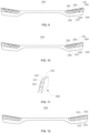
- FIG. 9 is a schematic diagram II of a lighting performance of a vehicle lamp module group 100 according to a first embodiment of the present disclosure.
- a user can select a lighting control instruction corresponding to a desired lighting mode according to a lighting mode option provided in an APP in the user terminal 13, and send a lighting control instruction of "lighting the low-beam unit 200 having two low-beam modules 101, and lighting the high-beam unit 300 having three interconnected high-beam modules 102" to the control module 121 through the user terminal 13; and the control module 121 controls the light sources 801 in the low-beam unit 200 ( FIG. 3(b) ) having two interconnected low-beam modules 101 and the high-beam unit 300 ( FIG.
- FIG. 10 is a schematic diagram III of a lighting performance of a vehicle lamp module group 100 according to a first embodiment of the present disclosure.
- the lighting mode in FIG. 10 is a lighting mode in which four low-beam units 200 ( FIG. 3(a) ) having one low-beam module 101 are added based on the lighting shown in FIG. 8 .
- a user can select a lighting control instruction corresponding to a desired lighting mode according to a lighting mode option provided in an APP in the user terminal 13, and send a lighting control instruction of "lighting the low-beam unit 200 having one low-beam module 101, and lighting the low-beam unit 200 having two low-beam modules 101" to the control module 121 through the user terminal 13; and the control module 121 controls the light sources 801 in the low-beam unit 200 ( FIG. 3(a) ) having one low-beam module 101 and in the low-beam unit 200 ( FIG. 3(b) ) having two interconnected low-beam modules 101 in the first row, and controls that in the low-beam unit 200 ( FIG.
- the vehicle lamp 12 can be used for road illumination with high light intensity low-beam illumination, such as illumination on an expressway.
- the signal lamp modules 103 in FIGs. 8 , 9 and 10 can always keep on or off state based as required.
- FIG. 11 is a structural schematic diagram of a module unit 500 of a vehicle lamp module group 100 according to a second embodiment of the present disclosure.
- the plurality of the low-beam modules 101 and the plurality of the high-beam modules 102 are arranged in a matrix, and may also be arranged in a matrix together with the signal lamp modules 103.
- one low-beam module 101 is arranged in two adjacent high-beam modules 102 shown in FIG. 11
- the signal lamp module 103 is connected to one of the high-beam modules 102.
- Each column of modules or each row of modules constitute one module unit 500, and the module unit 500 includes a housing 400 accommodating the modules.
- a structural schematic diagram of inside of the housing 400 is the same as that shown in FIGs. 5 to 7 , including a lens 600, a reflector 700, a circuit board 800, a light source 801 and a radiator 900. Details are not described herein again.
- FIG. 12 is a schematic diagram of a non-lighting performance of a vehicle lamp module group 100 according to a second embodiment of the present disclosure.
- the module units 500 shown in FIG. 11 are regularly arranged transversely according to the arrangement shown in FIG. 12 to form 11 columns of module units 500, so that the appearance of the vehicle lamp 12 is in a multi-column slash form.
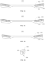
- FIG. 13 is a schematic diagram I of a lighting performance of a vehicle lamp module group 100 according to a second embodiment of the present disclosure.
- a user can select a lighting control instruction corresponding to a desired lighting mode according to a lighting mode option provided in an APP in the user terminal 13, and send a lighting control instruction of "lighting the bottommost high-beam modules 102 in the second, third, fourth and fifth columns, and lighting the low-beam modules 101 in the sixth, seventh, eighth, ninth, tenth and eleventh columns" to the control module 121 through the user terminal 13; and the control module 121 controls the light sources 801 of the bottommost high-beam modules 102 in the second, third, fourth and fifth columns and the low-beam modules in the sixth, seventh, eighth, ninth, tenth and eleventh columns of the vehicle lamp module group 100 to turn on according to the instruction, so as to realize the lighting mode of the six low-beam modules 101 and the four high-beam modules 102 shown by shaded parts in FIG
- FIG. 14 is a schematic diagram II of a lighting performance of a vehicle lamp module group 100 according to a second embodiment of the present disclosure.
- a user can select a lighting control instruction corresponding to a desired lighting mode according to a lighting mode option provided in an APP in the user terminal 13, and send a lighting control instruction of "lighting the low-beam modules 101 in the fourth, sixth, ninth and eleventh columns, and lighting the low-beam modules 101 and the high-beam modules 102 in the fifth and tenth columns" to the control module 121 through the user terminal 13; and the control module 121 controls the light sources 801 in the low-beam modules 101 in the fourth, sixth, ninth and eleventh columns, and the low-beam modules 101 and the high-beam modules 102 in the fifth and tenth columns of the vehicle lamp module group 100 to turn on according to the instruction, so as to realize the lighting mode of the six low-beam modules 101 and the four high-beam modules 102 shown by shaded parts in FIG. 14
- FIG. 15 is a schematic diagram III of a lighting performance of a vehicle lamp module group 100 according to a second embodiment of the present disclosure.
- a user can select a lighting control instruction corresponding to a desired lighting mode according to a lighting mode option provided in an APP in the user terminal 13, and send a lighting control instruction of "lighting the low-beam modules 101 in the first, third, fifth, seventh, ninth, and eleventh columns, lighting the bottommost high-beam modules 102 in the second, sixth, and tenth columns, and lighting the topmost high-beam modules 102 of the fourth and eighth columns" to the control module 121 through the user terminal 13; and the control module 121 controls the light sources 801 of the low-beam modules 101 in the first, third, fifth, seventh, ninth, and eleventh columns, the bottommost high-beam modules 102 in the second, sixth, and tenth columns, and the topmost low-beam modules 101 in the fourth and eighth columns of the vehicle lamp module group 100 to turn on according to
- the signal lamp modules 103 in FIGs. 13, 14 and 15 can always keep on/off state based as required.
- FIG. 16 is a structural schematic diagram of a module unit 500 of a vehicle lamp module group 100 according to a third embodiment of the present disclosure.
- One of the low-beam modules 101 and one of the signal lamp modules 103 are combined to form one module unit 500, and the module unit 500 includes a housing 400 accommodating the modules.
- a plurality of module units are arranged in a preset manner.
- the structural schematic diagram of the low-beam module 101 inside the housing 400 is the same as that shown in FIGs. 5 to 7 , including a lens 600, a reflector 700, a circuit board 800, a light source 801 and a radiator 900. Details are not described herein again.
- FIG. 17 is a structural schematic diagram II of a module unit 500 of a vehicle lamp module group 100 according to a third embodiment of the present disclosure.
- the module unit 500 includes a housing 400 accommodating the modules.
- a plurality of the module units 500 are arranged in a preset manner.
- the structural schematic diagram of the high-beam module 102 inside the housing 400 is the same as that shown in FIGs. 5 to 7 , including a lens 600, a reflector 700, a circuit board 800, a light source 801 and a radiator 900. Details are not described herein again.
- FIG. 18 is a schematic diagram of a non-lighting performance of a vehicle lamp module group 100 according to a third embodiment of the present disclosure.
- the module units 500 shown in FIG. 16 or FIG. 17 are arranged in an irregular mode in FIG. 18 .
- the number of the module units 500 having the high-beam module 102 is six, and the number of the module units 500 having the low-beam module 101 is ten.
- FIG. 19 is a schematic diagram I of a lighting performance of a vehicle lamp module group 100 according to a third embodiment of the present disclosure.
- a user can select a lighting control instruction corresponding to a desired lighting mode according to a lighting mode option provided in an APP in the user terminal 13, and send a lighting control instruction of "lighting six low-beam modules 101" to the control module 121 through the user terminal 13; and the control module 121 controls the light sources 801 in any six low-beam modules 101 in the vehicle lamp module group 100 to turn on according to the instruction, so as to realize the lighting mode of six low-beam modules 101 shown by the shaded parts in FIG. 19 , so that the vehicle lamp 12 can be used for low-beam illumination.
- FIG. 20 is a schematic diagram II of a lighting performance of a vehicle lamp module group 100 according to a third embodiment of the present disclosure.
- a user can select a lighting control instruction corresponding to a desired lighting mode according to a lighting mode option provided in an APP in the user terminal 13, and send a lighting control instruction of "lighting six high-beam modules 102 and lighting six low-beam modules 101" to the control module 121 through the user terminal 13; and the control module 121 controls the light sources 801 of the high-beam modules 102 and any six low-beam modules 101 in the vehicle lamp module group 100 to turn on according to the instruction, so as to realize lighting mode of six low-beam modules 101 and six high-beam modules 102 shown by shaded parts in FIG. 20 , so that the vehicle lamp 12 to be used for high-beam illumination.
- FIG. 21 is a schematic diagram III of a lighting performance of a vehicle lamp module group 100 according to a third embodiment of the present disclosure.
- a user can select a lighting control instruction corresponding to a desired lighting mode according to a lighting mode option provided in an APP in the user terminal 13, and send a lighting control instruction of "lighting ten low-beam modules 101" to the control module 121 through the user terminal 13; and the control module 121 controls the light sources 801 of all the low-beam modules 101 in the vehicle lamp module group 100 to turn on according to the instruction, so as to realize the lighting mode of ten low-beam modules 101 shown by shaded parts in FIG. 21 , so that the vehicle lamp 12 can be used for low-beam illumination, an enhancement mode of the low-beam illumination can be realized, and the illumination intensity thereof is higher than that in FIG. 19 , thereby meeting the different requirements of the customers.
- the signal lamp modules 103 in FIGs. 19, 20 and 21 can always keep on/off state as required.
- FIG. 22 is a light shape area diagram I of the emergent light of a low-beam module projected on a light distribution screen 101 according to an embodiment of the present disclosure.
- the light shape area has a low-beam cut-off line, which is formed by providing a cut-off line structure at a lower edge of the reflector 700.
- FIG. 23 is a light shape area diagram II of the emergent light of a low-beam module projected on a light distribution screen 101 according to an embodiment of the present disclosure.
- the light shape area has a low-beam III zone.
- FIG. 24 is a light shape area diagram III of the emergent light of a low-beam module projected on a light distribution screen 101 according to an embodiment of the present disclosure.
- the light shape area has a larger left-side widening angle.
- FIG. 25 shows a complete vehicle lamp low-beam illumination light shape formed by the emergent light of a plurality of low-beam modules 101 projected on a light distribution screen according to an embodiment of the present disclosure.
- FIG. 26 shows that another 2 low-beam units 200 are illuminated based on FIG. 25 , so that the widening angle on two sides of the low-beam light shape is increased, thereby increasing the range of low-beam illumination.
- the projected light of at least two low-beam modules 101 can jointly form a low-beam light shape
- the projected light of at least two high-beam modules 102 can jointly form a high-beam light shape. Therefore, a user may select a corresponding number of low-beam modules 101 and a corresponding number of high-beam modules 102 to realize high-beam and low-beam illumination; in addition, according to personal preferences, the user may select to present different lighting configurations of the low-beam modules 101, the high-beam modules 102 and signal lamp modules 103, such that the his/her own vehicle lamp 12 presents different appearance styles.
Landscapes
- Engineering & Computer Science (AREA)
- General Engineering & Computer Science (AREA)
- Mechanical Engineering (AREA)
- Physics & Mathematics (AREA)
- Microelectronics & Electronic Packaging (AREA)
- Optics & Photonics (AREA)
- Lighting Device Outwards From Vehicle And Optical Signal (AREA)
Applications Claiming Priority (2)
| Application Number | Priority Date | Filing Date | Title |
|---|---|---|---|
| CN202111339612.XA CN116123475A (zh) | 2021-11-12 | 2021-11-12 | 一种车灯模组、车灯及车辆 |
| PCT/CN2022/125336 WO2023082937A1 (fr) | 2021-11-12 | 2022-10-14 | Groupe de modules de phare de véhicule, phare de véhicule et véhicule |
Publications (2)
| Publication Number | Publication Date |
|---|---|
| EP4360954A1 true EP4360954A1 (fr) | 2024-05-01 |
| EP4360954A4 EP4360954A4 (fr) | 2024-11-13 |
Family
ID=86294302
Family Applications (1)
| Application Number | Title | Priority Date | Filing Date |
|---|---|---|---|
| EP22891734.0A Pending EP4360954A4 (fr) | 2021-11-12 | 2022-10-14 | Groupe de modules de phare de véhicule, phare de véhicule et véhicule |
Country Status (3)
| Country | Link |
|---|---|
| EP (1) | EP4360954A4 (fr) |
| CN (1) | CN116123475A (fr) |
| WO (1) | WO2023082937A1 (fr) |
Family Cites Families (14)
| Publication number | Priority date | Publication date | Assignee | Title |
|---|---|---|---|---|
| CN102267416A (zh) * | 2011-05-17 | 2011-12-07 | 毛鹏飞 | 机动车车灯控制系统 |
| CN102358231A (zh) * | 2011-08-22 | 2012-02-22 | 大连民族学院 | 汽车灯光控制系统及方向盘 |
| KR20150072085A (ko) * | 2013-12-19 | 2015-06-29 | 에스엘 주식회사 | 차량용 램프 |
| US9587794B2 (en) * | 2014-05-21 | 2017-03-07 | Ford Global Technologies, Llc | Headlamp assembly with multiple high aspect ratio lenses |
| DE102016125887A1 (de) * | 2016-12-29 | 2018-07-05 | Automotive Lighting Reutlingen Gmbh | Lichtmodul für Kraftfahrzeugscheinwerfer |
| KR102094679B1 (ko) * | 2017-04-11 | 2020-04-01 | 제트카베 그룹 게엠베하 | 차량용 레이저 헤드 램프 및 차량 |
| CN208504240U (zh) * | 2017-12-09 | 2019-02-15 | 黑龙江矩阵光学科技有限公司 | 拼接式矩阵led汽车远近光模块 |
| FR3087395B1 (fr) * | 2018-10-22 | 2021-02-26 | Psa Automobiles Sa | Dispositif d’eclairage avant pour vehicule automobile |
| CN208967707U (zh) * | 2018-11-26 | 2019-06-11 | 深圳智诺车灯科技有限公司 | 一种近光前照灯模组 |
| US20200398738A1 (en) * | 2019-06-20 | 2020-12-24 | Hyundai Mobis Co., Ltd. | Headlamp for vehicle and method for controlling the same |
| CN110748851A (zh) * | 2019-10-11 | 2020-02-04 | 华南理工大学 | 一种汽车前照灯光学系统 |
| KR102704123B1 (ko) * | 2019-11-01 | 2024-09-06 | 에스엘 주식회사 | 차량용 램프 |
| CN211475817U (zh) * | 2020-04-22 | 2020-09-11 | 浙江嘀视科技有限公司 | 一种矩阵型六灯远近光透镜总成 |
| CN113459940B (zh) * | 2021-06-30 | 2024-07-12 | 奇瑞汽车股份有限公司 | 一种智能多发光形态的昼间行车灯控制系统及方法 |
-
2021
- 2021-11-12 CN CN202111339612.XA patent/CN116123475A/zh active Pending
-
2022
- 2022-10-14 EP EP22891734.0A patent/EP4360954A4/fr active Pending
- 2022-10-14 WO PCT/CN2022/125336 patent/WO2023082937A1/fr not_active Ceased
Also Published As
| Publication number | Publication date |
|---|---|
| EP4360954A4 (fr) | 2024-11-13 |
| WO2023082937A1 (fr) | 2023-05-19 |
| CN116123475A (zh) | 2023-05-16 |
Similar Documents
| Publication | Publication Date | Title |
|---|---|---|
| US8258704B2 (en) | Vehicle lighting display system | |
| CN101660676B (zh) | 灯 | |
| KR101310746B1 (ko) | 차량용 등구 | |
| CN102635821A (zh) | 以单灯形成多个配光图案的车辆用前照灯 | |
| US11920755B2 (en) | Automotive headlamp system and automotive lamp | |
| CN206522715U (zh) | 汽车尾灯 | |
| US11204147B1 (en) | Headlight unit having micro-light emitting diode device, relay lens system and projection lens system | |
| CN114484369A (zh) | 一种贯穿式汽车前大灯结构 | |
| US9725030B2 (en) | Vehicle light and vehicle equipped with vehicle light | |
| CN107435882A (zh) | 照明装置 | |
| EP4360954A1 (fr) | Groupe de modules de phare de véhicule, phare de véhicule et véhicule | |
| JP6470020B2 (ja) | 照明装置 | |
| EP2536591B1 (fr) | Ensemble lumineux d'avertissement; composants; et procédés | |
| EP3950427B1 (fr) | Appareil d'éclairage de véhicule | |
| KR102695903B1 (ko) | 차량용 램프 시스템 | |
| JP7453806B2 (ja) | 車両用ランプ | |
| JP4023777B2 (ja) | 車両用led灯具 | |
| JPH08227603A (ja) | 車輌用表示ランプ | |
| CN207762815U (zh) | 一种汽车边灯 | |
| JP2005317348A (ja) | 表示装置及び信号灯 | |
| CN212195723U (zh) | 后尾灯结构及摩托车 | |
| WO2023167274A1 (fr) | Dispositif d'éclairage de bicyclette | |
| CN221611193U (zh) | 基于激光测距模组的自适应多光型灯具 | |
| TW201242812A (en) | Composite fog light device with daytime running light function | |
| CN221780560U (zh) | 车灯配光花纹结构、厚壁件、灯罩系统、照明装置、车灯 |
Legal Events
| Date | Code | Title | Description |
|---|---|---|---|
| STAA | Information on the status of an ep patent application or granted ep patent |
Free format text: STATUS: THE INTERNATIONAL PUBLICATION HAS BEEN MADE |
|
| PUAI | Public reference made under article 153(3) epc to a published international application that has entered the european phase |
Free format text: ORIGINAL CODE: 0009012 |
|
| STAA | Information on the status of an ep patent application or granted ep patent |
Free format text: STATUS: REQUEST FOR EXAMINATION WAS MADE |
|
| 17P | Request for examination filed |
Effective date: 20240125 |
|
| AK | Designated contracting states |
Kind code of ref document: A1 Designated state(s): AL AT BE BG CH CY CZ DE DK EE ES FI FR GB GR HR HU IE IS IT LI LT LU LV MC ME MK MT NL NO PL PT RO RS SE SI SK SM TR |
|
| REG | Reference to a national code |
Ref country code: DE Ref legal event code: R079 Free format text: PREVIOUS MAIN CLASS: B60Q0001140000 Ipc: F21S0041663000 |
|
| STAA | Information on the status of an ep patent application or granted ep patent |
Free format text: STATUS: EXAMINATION IS IN PROGRESS |
|
| A4 | Supplementary search report drawn up and despatched |
Effective date: 20241016 |
|
| RIC1 | Information provided on ipc code assigned before grant |
Ipc: B60Q 1/00 20060101ALI20241010BHEP Ipc: F21S 41/147 20180101ALI20241010BHEP Ipc: F21S 41/663 20180101AFI20241010BHEP |
|
| 17Q | First examination report despatched |
Effective date: 20241028 |
|
| DAV | Request for validation of the european patent (deleted) | ||
| DAX | Request for extension of the european patent (deleted) |