EP4360962A1 - Seitenairbag - Google Patents
Seitenairbag Download PDFInfo
- Publication number
- EP4360962A1 EP4360962A1 EP22203391.2A EP22203391A EP4360962A1 EP 4360962 A1 EP4360962 A1 EP 4360962A1 EP 22203391 A EP22203391 A EP 22203391A EP 4360962 A1 EP4360962 A1 EP 4360962A1
- Authority
- EP
- European Patent Office
- Prior art keywords
- bag
- air
- fabric
- layer
- vehicle
- Prior art date
- Legal status (The legal status is an assumption and is not a legal conclusion. Google has not performed a legal analysis and makes no representation as to the accuracy of the status listed.)
- Pending
Links
Images






Classifications
-
- B—PERFORMING OPERATIONS; TRANSPORTING
- B60—VEHICLES IN GENERAL
- B60R—VEHICLES, VEHICLE FITTINGS, OR VEHICLE PARTS, NOT OTHERWISE PROVIDED FOR
- B60R21/00—Arrangements or fittings on vehicles for protecting or preventing injuries to occupants or pedestrians in case of accidents or other traffic risks
- B60R21/02—Occupant safety arrangements or fittings, e.g. crash pads
- B60R21/16—Inflatable occupant restraints or confinements designed to inflate upon impact or impending impact, e.g. air bags
- B60R21/23—Inflatable members
- B60R21/237—Inflatable members characterised by the way they are folded
-
- B—PERFORMING OPERATIONS; TRANSPORTING
- B60—VEHICLES IN GENERAL
- B60R—VEHICLES, VEHICLE FITTINGS, OR VEHICLE PARTS, NOT OTHERWISE PROVIDED FOR
- B60R21/00—Arrangements or fittings on vehicles for protecting or preventing injuries to occupants or pedestrians in case of accidents or other traffic risks
- B60R21/02—Occupant safety arrangements or fittings, e.g. crash pads
- B60R21/16—Inflatable occupant restraints or confinements designed to inflate upon impact or impending impact, e.g. air bags
- B60R21/23—Inflatable members
- B60R21/231—Inflatable members characterised by their shape, construction or spatial configuration
- B60R21/23138—Inflatable members characterised by their shape, construction or spatial configuration specially adapted for side protection
-
- B—PERFORMING OPERATIONS; TRANSPORTING
- B60—VEHICLES IN GENERAL
- B60R—VEHICLES, VEHICLE FITTINGS, OR VEHICLE PARTS, NOT OTHERWISE PROVIDED FOR
- B60R21/00—Arrangements or fittings on vehicles for protecting or preventing injuries to occupants or pedestrians in case of accidents or other traffic risks
- B60R21/02—Occupant safety arrangements or fittings, e.g. crash pads
- B60R21/16—Inflatable occupant restraints or confinements designed to inflate upon impact or impending impact, e.g. air bags
- B60R21/23—Inflatable members
- B60R21/231—Inflatable members characterised by their shape, construction or spatial configuration
- B60R21/2334—Expansion control features
- B60R21/2342—Tear seams
Definitions
- the present invention relates to a side air-bag for a motor vehicle.
- the present invention more particularly relates to a side air-bag to protect an occupant of a vehicle in the event of a crash situation.
- a side air-bag is a safety device that is mounted within a vehicle to protect an occupant of the vehicle in the event of a crash situation.
- a side air-bag is particularly beneficial in protecting an occupant of a vehicle in the event that the vehicle is involved in a side impact.
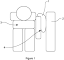
- Figure 1 of the accompanying drawings shows a conventional side air-bag 1 in an inflated configuration, after having been deployed.
- the inflated air-bag 1 is position between a door 2 of the vehicle and an occupant 3 of the vehicle.
- the air-bag 1 acts as a cushion that restricts movement of the occupant 3 relative to the door 2.
- the air-bag 1 dissipates kinetic energy of the occupant 3 to minimise the risk of the occupant 3 striking the door 2 during the crash situation.
- a problem with side air-bags such as the air-bag 1 shown in Figure 1 , is that the air-bag typically does not contact the torso of the occupant 3 sufficiently. This can lead to high forces being exerted by the inflated air-bag on the arm 4 and the shoulder of the occupant 3, which can in turn cause injury to the arm 4, shoulder or the ribs of the occupant 3.
- the present invention provides a side air-bag as claimed in claim 1 and a side air-bag module as claimed in claim 7.
- the present invention also provides preferred embodiments as claimed in the dependent claims.
- the air-bag of some examples of this disclosure fills the space between the door of a vehicle and the torso of an occupant of the vehicle fully, thereby stabilising and minimising movement of the occupant of the vehicle during a crash situation.
- the air-bag of some examples of this disclosure rotates the arm of an occupant during deployment which leads to more inboard positioning of the inflated air-bag relative to a conventional side air-bag. This further inboard positioning further enhances the protection to the vehicle occupant as compared with a conventional side air-bag.
- the air-bag of some examples of this disclosure can be configured easily to inflate in a desired manner for a particular vehicle type by changing the number of pleats and/or the position of the pleats in the air-bag. Such flexibility is not possible with standard conventional side air-bags that are not folded with pleats.
- the air-bag of some examples of this disclosure is provided with at least one pleat that unfolds as the air-bag inflates to increase the volume of the air-bag and fully fill the space on one side of an occupant of a vehicle. This avoids the need to add additional chambers to increase the volume of the air-bag that would otherwise increase the weight and packing size of the air-bag.
- the air-bag of some examples of this disclosure does not require tethers to be fixed to the air-bag to achieve a curved shape upon inflation of the air-bag. This means that the air-bag can be packed into a smaller enclosure than conventional air-bags that incorporate additional components, such as tethers, baffles or panels.
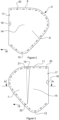
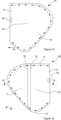
- a side air-bag of an example of this disclosure comprises an elongate first layer of fabric 6 and an elongate second layer of fabric 7.
- the first and second layers of fabric 6, 7 are formed integrally with one another and folded along a fold line 8 so that the layers of fabric 6, 7 are superimposed on one another.
- the first and second layers of fabric 6, 7 are initially separate but joined to on another during the manufacturing process.
- the first and second layers of fabric 6, 7 are elongate in the sense that the first and second layers of fabric 6,7 have a length which extends between a first end 9 and a second end 10 of the first layer of fabric 6 or between a first end 11 and a second end 12 of the second layer of fabric 7. It is to be appreciated that the first ends 9, 11 are at the top of the air-bag 5 and the second ends 10, 12 are at the bottom of the air-bag 5 when the air-bag is inflated within a vehicle.
- the second layer of fabric 7 is superimposed on the first layer of fabric 6 to form a chamber 13 between a section 14 of the first layer of fabric 6 and a section 15 of the second layer of fabric 7.
- the sections 14, 15 of the first and second layers of fabric 6, 7 are central sections of the first and second layers of fabric 6, 7.
- the air-bag 5 is provided with a gas inlet aperture 16 which, in this example, is positioned at the fold line 8 between the first and second layers of fabric 6, 7.
- the air-bag 5 is provided with a mounting aperture 17 in the vicinity of the gas inlet aperture 16 to receive a mounting element to mount a gas generator to the air-bag 5.
- the mounting aperture 17 is omitted.
- the second layer of fabric 7 is wider than the first layer of fabric 6 in a transverse direction that extends transverse to the lengths of the first and second layers of fabric 6, 7.
- the transverse direction is generally indicated by arrows 18 in Figures 2 and 3 .
- the transverse direction 18 is perpendicular or generally perpendicular to a longitudinal axis extending between the first and 9 and the second and 10 of the first layer of fabric and/or the first end 11 and the second end 12 of the second layer of fabric 7.
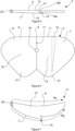
- the second layer of fabric 7 is folded with at least one elongate pleat 19.
- the pleat 19 is formed from a first fold 19a and a second fold 19b, which together form a Z-fold in the second layer of fabric 7.
- the air-bag of other examples of this disclosure comprises at least one pleat having a different fold shape.
- the at least one elongate pleat 19 reduces the overall width of the second layer of fabric 7 so that the second layer of fabric 7 is the same or is a similar width to the first layer of fabric 6, as shown in Figures 2 and 3 . Therefore, despite the second layer of fabric having a greater width than the first layer of fabric 6, the at least one pleat allows for the second layer of fabric 7 to sit generally flat when superimposed on the first layer of fabric 6.
- the first and second layers of fabric 6, 7 are superimposed on one another and the first and second layers of fabric 6, 7 are stitched together along a seam 20 that extends at least partly around periphery of the first layer of fabric 6 and the second layer of fabric 7.
- the seam 20 provides a gas tight or substantially gas tight seal that minimises or prevents gas from leaking out from the air-bag 5 upon inflation.
- the pleat 19 has a first end 21 and a second end 22.
- the first end 21 of the pleat 19 is positioned at the first end 11 of the second layer of fabric 7.
- the second end 22 of the pleat 19 is spaced apart from the second end 12 of the second layer of fabric 7 and is position at the section 15 of the second layer of fabric. That is to say, the second end 22 of the pleat 19 is spaced apart from the seam 20 at the second end 12 of the second layer of fabric 7 and located at the section 15 of the second layer of fabric that moves apart from the first layer of fabric 6 upon inflation of the air-bag 5.
- the pleat 19 is V-shaped or substantially V-shaped.
- the V-shape is achieved by the distance over which the second layer of fabric 7 is folded being greater at the first end 21 of the pleat 19 than at the second end 22 of the pleat 19.
- the V-shape controls the shape of the air-bag 5 upon inflation, such that the upper end of the air-bag 5 at the first ends 9, 11 of the first and second layers of fabric 6, 7 has a wider cross-section than the lower end of the air-bag 5 at the second ends 10, 12 of the first and second layers of fabric 6, 7.
- the shape of the pleat 19 of this example is one type of shape and other examples of this disclosure comprise pleats of a different shape. Examples of air-bags of this disclosure having pleats of a different shape and/or a different number of pleats are described below.
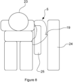
- the air-bag 5 is positioned between a door 24 or a wall of a vehicle and the occupant 23.
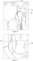
- the curved shape of the air-bag 5 leads to the air-bag 5 exerting a rotational force on an arm 25 of the occupant 23 that moves the occupant arm 25 upwardly.
- the rotation of the occupant's arm 25 enables the air-bag 5 to fit around the torso of the occupant 23.
- the air-bag 5 fully fills the space between the torso of the occupant 23 and the door 24 due to the increased volume of the air-bag resulting from each pleat unfolding during inflation of the air-bag. This provides improved stabilisation that minimises movement of the occupant 23 relative to the door 24 and helps minimise injury to the occupant 23 during a crash situation.
- the positioning achieved by the curved air-bag 5 minimises forces on the arm and shoulder of the occupant 23 that might otherwise result in injury to the occupant 23.
- Air-bags of other examples of this disclosure will now be described.
- the air-bags of other examples comprise many of the same elements as the air-bag 5 described above and the same reference numbers are used for the equivalent components in the air-bag described below.
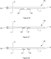
- an air-bag 26 of another example of this disclosure comprises a second layer of fabric 7 that is folded with an elongate pleat 27.
- a first end 28 of the pleat 27 is positioned at the first end 11 of the second layer of fabric 7 and a second end 29 of the pleat 27 is positioned at the second end 12 of the second layer of fabric 7.
- the pleat 27 extends across substantially the entire height of the second layer of fabric 7 between the seam 20 at the first and 11 and the seam 20 at the second and 12 of the second layer of fabric 7.
- the pleat 27 of the air-bag 26 is formed by a Z-fold in the second layer of fabric 7.
- the Z-fold is formed by a first fold 27a in a first fold direction and a second fold 27b in a second fold direction.
- the first fold direction is in a different direction to the second fold direction. In this example, the first fold direction is opposite to the second fold direction.
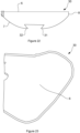
- an air-bag 30 of another example of this disclosure comprises a second layer of fabric 7 that is folded with two elongate pleats 31, 32.
- the two elongate pleats 31, 32 are folded in opposite directions to one another and are spaced apart from one another.
- the pleats 31, 32 form an omega fold in the second layer of fabric 7, as shown in Figure 20 .
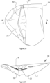
- the air-bag 30 when the air-bag 30 is inflated, the sections 14, 15 of the first and second layers of fabric 6, 7 move apart from one another and unfold each pleat 31, 32 in the second layer of fabric 7.
- the inflated air-bag 30 has a curved shape to fit around part of an occupant of a motor vehicle.
- the spacing between the pleats 31, 32 result in the degree of curvature of the second layer of fabric 7 upon inflation of the air-bag 30 being different from the degree of curvature of the air-bags of the examples described above.
- an air-bag 33 of another example of this disclosure comprises a second layer of fabric 7 that is folded with two spaced apart pleats 34, 35.
- the two spaced apart pleats 34, 35 form an omega fold that is similar to the omega fold of the air-bag 30 described above.
- the omega fold of the air-bag 33 is reversed such that the folded portions of the pleats 34, 35 project outwardly from the plane of the second layer of fabric 7.
- an air-bag 36 of another example of this disclosure comprises a second layer of fabric 7 which is folded with two spaced apart pleats 37, 38.
- the pleats 37, 38 are folded in substantially the same direction as one another to form two spaced apart Z-folds in the second layer of fabric 7.
- the pleats 37, 38 are folded in the same direction as one another, away from the fold line 8 of the air-bag 36.
- an air-bag 39 of a further example of this disclosure comprises a second layer of fabric 7 which is provided with two spaced apart pleats 40, 41.
- the pleats 40, 41 are folded in the same direction as on another and are folded towards the fold line 8 of the air-bag 39.
- an air-bag 42 of another example of this disclosure comprises three spaced apart pleats 43-45 which are folded in the second layer of fabric 7.
- the pleats 43-45 are all folded in the same direction towards the fold line 8 of the air-bag 42.
- the first two pleats 43,44 are closer to one another than the spacing between the second pleat 44 and the third pleat 45.
- air-bags of some examples of this disclosure are provided with one pleat or a plurality of pleats in the second layer of fabric 7 to achieve a desired degree of curvature of the air-bag upon inflation.
- the type of fold and the number and spacing of the pleats is selected to achieve a desired degree of curvature of the inflated air-bag to provide an appropriate restraint for an occupant of a vehicle.
- an air-bag 46 of other examples of this disclosure is a farside air-bag to be inflated centrally within a vehicle between two seats, as shown in Figure 32 .
- the farside air-bag 46 is of the same configuration and comprises the same elements as the other air-bags described above to ensure that the air-bag 46 has a curved shape upon inflation.
- the air-bag 46 fits around part of an occupant 23 and stabilises the occupant 23 to minimise movement of the occupant 23 during a crash situation.
- the stabilisation provided by the inflated air-bag 46 reduces the risk of injury to the occupant 23 by minimising or preventing the occupant 23 from moving towards the centre of the vehicle and potentially striking an adjacent passenger 47.
- an air-bag of the type described above comprises an insert or gas diffuser that is coupled to the air-bag adjacent to the gas inlet opening 16.
- the insert is configured to be mounted to a gas generator.
- a side air-bag module comprises an enclosure, a gas generator and an air-bag of one of the examples described above.
- the gas generator is mounted to an insert that is coupled to the air-bag and the air-bag is folded and received within the enclosure.
- the enclosure is a flexible wrap but in other examples the enclosure is a rigid plastic housing.
- the configuration of the air-bag with at least one pleat enables the air-bag to inflate to a greater volume as each pleat unfolds upon inflation of the air-bag as compared with an air-bag without pleats. This enables the air-bag to fully fill the space between an occupant of a vehicle and the door of the vehicle (in the case of a nearside air-bag) or the space between the occupant and a passenger (in the case of a farside air-bag).
- the at least one pleat achieves the greater inflation volume without needing to add additional chambers to the air-bag, which would undesirably increase the size and shape of the air-bag.
- the configuration of the air-bag with at least one pleat reduces the packing space required for the air-bag as compared with a conventional air-bag that incorporates tethers achieve a curved inflated shaped. This helps minimise the overall size of the enclosure of the air-bag module. Furthermore, it is easier to manufacture the air-bag of examples of this disclosure with at least one pleat compared with other air-bags that require additional components, such as tethers, baffles or panels to be attached within the air-bag to control the shape of the inflated air-bag.
- the invention may also broadly consist in the parts, elements, steps, examples and/or features referred to or indicated in the specification individually or collectively in any and all combinations of two or more said parts, elements, steps, examples and/or features.
- one or more features in any of the embodiments described herein may be combined with one or more features from any other embodiment(s) described herein.
Landscapes
- Engineering & Computer Science (AREA)
- Mechanical Engineering (AREA)
- Air Bags (AREA)
Priority Applications (3)
| Application Number | Priority Date | Filing Date | Title |
|---|---|---|---|
| EP22203391.2A EP4360962A1 (de) | 2022-10-24 | 2022-10-24 | Seitenairbag |
| CN202380070185.0A CN119998178A (zh) | 2022-10-24 | 2023-09-29 | 侧面安全气囊 |
| PCT/EP2023/077079 WO2024088695A1 (en) | 2022-10-24 | 2023-09-29 | Side air-bag |
Applications Claiming Priority (1)
| Application Number | Priority Date | Filing Date | Title |
|---|---|---|---|
| EP22203391.2A EP4360962A1 (de) | 2022-10-24 | 2022-10-24 | Seitenairbag |
Publications (1)
| Publication Number | Publication Date |
|---|---|
| EP4360962A1 true EP4360962A1 (de) | 2024-05-01 |
Family
ID=83995041
Family Applications (1)
| Application Number | Title | Priority Date | Filing Date |
|---|---|---|---|
| EP22203391.2A Pending EP4360962A1 (de) | 2022-10-24 | 2022-10-24 | Seitenairbag |
Country Status (3)
| Country | Link |
|---|---|
| EP (1) | EP4360962A1 (de) |
| CN (1) | CN119998178A (de) |
| WO (1) | WO2024088695A1 (de) |
Citations (4)
| Publication number | Priority date | Publication date | Assignee | Title |
|---|---|---|---|---|
| EP0988185B1 (de) * | 1997-06-12 | 2001-09-19 | Petri AG | Seitenairbagmodul |
| FR2824029B1 (fr) * | 2001-04-27 | 2003-11-21 | Aerazur | Sac gonflable de securite a deploiement oriente et progressif |
| DE102006047902A1 (de) * | 2006-10-10 | 2008-04-17 | Trw Automotive Gmbh | Gassack |
| EP3778310B1 (de) * | 2018-04-05 | 2022-07-13 | Autoliv Development AB | Seitenairbagvorrichtung |
-
2022
- 2022-10-24 EP EP22203391.2A patent/EP4360962A1/de active Pending
-
2023
- 2023-09-29 WO PCT/EP2023/077079 patent/WO2024088695A1/en not_active Ceased
- 2023-09-29 CN CN202380070185.0A patent/CN119998178A/zh active Pending
Patent Citations (4)
| Publication number | Priority date | Publication date | Assignee | Title |
|---|---|---|---|---|
| EP0988185B1 (de) * | 1997-06-12 | 2001-09-19 | Petri AG | Seitenairbagmodul |
| FR2824029B1 (fr) * | 2001-04-27 | 2003-11-21 | Aerazur | Sac gonflable de securite a deploiement oriente et progressif |
| DE102006047902A1 (de) * | 2006-10-10 | 2008-04-17 | Trw Automotive Gmbh | Gassack |
| EP3778310B1 (de) * | 2018-04-05 | 2022-07-13 | Autoliv Development AB | Seitenairbagvorrichtung |
Also Published As
| Publication number | Publication date |
|---|---|
| CN119998178A (zh) | 2025-05-13 |
| WO2024088695A1 (en) | 2024-05-02 |
Similar Documents
| Publication | Publication Date | Title |
|---|---|---|
| KR102491286B1 (ko) | 차량 시트 | |
| US8047564B2 (en) | Airbag | |
| KR100194484B1 (ko) | 에어 백 | |
| US8196955B2 (en) | Airbag system | |
| US7770925B2 (en) | Airbag protection flap | |
| CN102099227B (zh) | 机动车辆的车辆座椅设备和气囊设备及保护车辆乘员的方法 | |
| US8181990B2 (en) | Multiple chamber airbag system | |
| JP4391308B2 (ja) | エアバッグ装置 | |
| EP3720740B1 (de) | Seitenairbag mit akkordeonbeckenfaltenfaltung | |
| KR20020037764A (ko) | 동역학적 전개 장치 차폐물 | |
| BR112017021358B1 (pt) | Dispositivo de proteção de ocupante | |
| KR20200029022A (ko) | 승차인 보호 장치 | |
| CN111247039A (zh) | 具有气囊模块的车辆乘员约束系统和用于集拢气囊的方法 | |
| US20240140348A1 (en) | Center side airbag | |
| EP2519426B1 (de) | Airbag mit einem schlitz im randbereich | |
| JP4376596B2 (ja) | エアバッグ装置 | |
| CN111247041A (zh) | 具有气囊模块的车辆乘员约束系统 | |
| CN112061070B (zh) | 侧面安全气囊装置 | |
| US6918868B2 (en) | Inflatable restraint system for an air bag | |
| JP2011111075A (ja) | エアバッグ及びエアバッグの折畳方法 | |
| KR101699109B1 (ko) | 에어백 장치 | |
| CN114802088A (zh) | 安全气囊装置 | |
| KR100574758B1 (ko) | 에어백 모듈 조립체 및 그 조립 방법 | |
| EP4360962A1 (de) | Seitenairbag | |
| US6331015B1 (en) | Air bag fold and method |
Legal Events
| Date | Code | Title | Description |
|---|---|---|---|
| PUAI | Public reference made under article 153(3) epc to a published international application that has entered the european phase |
Free format text: ORIGINAL CODE: 0009012 |
|
| STAA | Information on the status of an ep patent application or granted ep patent |
Free format text: STATUS: THE APPLICATION HAS BEEN PUBLISHED |
|
| AK | Designated contracting states |
Kind code of ref document: A1 Designated state(s): AL AT BE BG CH CY CZ DE DK EE ES FI FR GB GR HR HU IE IS IT LI LT LU LV MC ME MK MT NL NO PL PT RO RS SE SI SK SM TR |
|
| STAA | Information on the status of an ep patent application or granted ep patent |
Free format text: STATUS: REQUEST FOR EXAMINATION WAS MADE |
|
| 17P | Request for examination filed |
Effective date: 20241028 |
|
| RBV | Designated contracting states (corrected) |
Designated state(s): AL AT BE BG CH CY CZ DE DK EE ES FI FR GB GR HR HU IE IS IT LI LT LU LV MC ME MK MT NL NO PL PT RO RS SE SI SK SM TR |
|
| STAA | Information on the status of an ep patent application or granted ep patent |
Free format text: STATUS: EXAMINATION IS IN PROGRESS |
|
| 17Q | First examination report despatched |
Effective date: 20260325 |