EP4360997A1 - Dispositif de direction - Google Patents
Dispositif de direction Download PDFInfo
- Publication number
- EP4360997A1 EP4360997A1 EP22826644.1A EP22826644A EP4360997A1 EP 4360997 A1 EP4360997 A1 EP 4360997A1 EP 22826644 A EP22826644 A EP 22826644A EP 4360997 A1 EP4360997 A1 EP 4360997A1
- Authority
- EP
- European Patent Office
- Prior art keywords
- support member
- bearing support
- slit
- peripheral surface
- housing
- Prior art date
- Legal status (The legal status is an assumption and is not a legal conclusion. Google has not performed a legal analysis and makes no representation as to the accuracy of the status listed.)
- Pending
Links
Images


Classifications
-
- B—PERFORMING OPERATIONS; TRANSPORTING
- B62—LAND VEHICLES FOR TRAVELLING OTHERWISE THAN ON RAILS
- B62D—MOTOR VEHICLES; TRAILERS
- B62D5/00—Power-assisted or power-driven steering
- B62D5/04—Power-assisted or power-driven steering electrical, e.g. using an electric servo-motor connected to, or forming part of, the steering gear
- B62D5/0409—Electric motor acting on the steering column
-
- B—PERFORMING OPERATIONS; TRANSPORTING
- B62—LAND VEHICLES FOR TRAVELLING OTHERWISE THAN ON RAILS
- B62D—MOTOR VEHICLES; TRAILERS
- B62D5/00—Power-assisted or power-driven steering
- B62D5/04—Power-assisted or power-driven steering electrical, e.g. using an electric servo-motor connected to, or forming part of, the steering gear
- B62D5/0442—Conversion of rotational into longitudinal movement
- B62D5/0454—Worm gears
-
- B—PERFORMING OPERATIONS; TRANSPORTING
- B62—LAND VEHICLES FOR TRAVELLING OTHERWISE THAN ON RAILS
- B62D—MOTOR VEHICLES; TRAILERS
- B62D5/00—Power-assisted or power-driven steering
- B62D5/04—Power-assisted or power-driven steering electrical, e.g. using an electric servo-motor connected to, or forming part of, the steering gear
- B62D5/0403—Power-assisted or power-driven steering electrical, e.g. using an electric servo-motor connected to, or forming part of, the steering gear characterised by constructional features, e.g. common housing for motor and gear box
-
- B—PERFORMING OPERATIONS; TRANSPORTING
- B62—LAND VEHICLES FOR TRAVELLING OTHERWISE THAN ON RAILS
- B62D—MOTOR VEHICLES; TRAILERS
- B62D6/00—Arrangements for automatically controlling steering depending on driving conditions sensed and responded to, e.g. control circuits
- B62D6/08—Arrangements for automatically controlling steering depending on driving conditions sensed and responded to, e.g. control circuits responsive only to driver input torque
- B62D6/10—Arrangements for automatically controlling steering depending on driving conditions sensed and responded to, e.g. control circuits responsive only to driver input torque characterised by means for sensing or determining torque
Definitions
- the present disclosure relates to a steering device.
- a steering device of Patent Document 1 includes a motor and a metal housing.
- the housing houses a torque sensor and a worm gear mechanism.
- the motor generates a torque based on a steering torque detected by the torque sensor.
- the torque of the motor is transmitted to a steering shaft via the worm gear mechanism.
- the housing includes a worm housing member and a sensor housing member.
- the worm housing member houses the worm gear mechanism.
- the sensor housing member houses the torque sensor.
- the worm housing member and the sensor housing member are fitted together in an axial direction of the steering shaft.
- the steering shaft is supported via bearings so as to be rotatable relative to the worm housing member and the sensor housing member.
- Patent Document 1 Japanese Unexamined Patent Application Publication No. 2020-90139 ( JP 2020-90139 A )
- a steering device includes a cylindrical support tube that includes a flange and that rotatably supports a steering shaft, a speed reducer configured to apply a torque to the steering shaft, a housing that includes a cylindrical portion housing the speed reducer, the cylindrical portion being disposed coaxially with the flange, a bolt that couples the flange and the cylindrical portion to each other, a bearing support member that is fitted to an inner peripheral surface of the cylindrical portion and through which the steering shaft extends, and a bearing interposed between an outer peripheral surface of the steering shaft and an inner peripheral surface of the bearing support member.
- the bearing support member includes a deformation allowing portion configured to allow elastic deformation of the bearing support member in a radial direction.
- a steering device 1 includes a steering shaft 2, an intermediate shaft 3, a pinion shaft 4, and a rack shaft 5.
- a steering wheel 6 is coupled to a first end of the steering shaft 2.
- a first end of the intermediate shaft 3 is coupled to a second end of the steering shaft 2 via a universal joint 7.
- a first end of the pinion shaft 4 is coupled to a second end of the intermediate shaft 3 via a universal joint 8.
- a pinion 4a is provided at a second end of the pinion shaft 4.
- the pinion 4a meshes with a rack 5a provided on the rack shaft 5.
- the rack shaft 5 is supported inside a housing 10 fixed to a frame 9 of a vehicle body.
- the rack shaft 5 is movable in a right direction or a left direction with respect to a direction of travel of a vehicle. Both ends of the rack shaft 5 are coupled to right and left steered wheels (not shown) via tie rods (not shown).
- the steering shaft 2 includes an outer shaft 11 and an inner shaft 12.
- the outer shaft 11 and the inner shaft 12 are coupled to each other by, for example, spline coupling.
- the outer shaft 11 and the inner shaft 12 can rotate together and can move relatively in their axial direction.
- the steering shaft 2 is disposed so as to be inclined with respect to a front-rear direction of the vehicle with the steering wheel 6 facing upward.
- the steering device 1 includes a steering column 15.
- the steering shaft 2 is inserted through the steering column 15.
- the steering shaft 2 is supported via a bearing (not shown) so as to be rotatable relative to the steering column 15.
- the steering column 15 is attached to two frames 13, 14 provided on the vehicle body. One frame 13 is positioned behind the other frame 14 in the front-rear direction of the vehicle.
- the steering column 15 includes an upper tube 16, a lower tube 17, and a housing 18.
- the upper tube 16 has a cylindrical shape.
- the lower tube 17 has a cylindrical shape and includes a flange 31.
- the upper tube 16 and the lower tube 17 are fitted together.
- the upper tube 16 is inserted into a first end of the lower tube 17.
- the first end is an end opposite to a second end with the flange 31.
- the upper tube 16 and the lower tube 17 can move relative to each other in the axial direction of the steering shaft 2.
- the lower tube 17 includes a column bracket 17A.
- the lower tube 17 is attached to the frame 13 of the vehicle body via the column bracket 17A.
- the upper tube 16 and the lower tube 17 constitute a support tube that rotatably supports the steering shaft 2.
- the housing 18 is coupled to the second end of the lower tube 17.
- the housing 18 includes two support portions 18A (only one is shown in FIG. 1 ) and a support shaft 18B.
- the two support portions 18A are provided on the side surface of the housing 18 opposite to the lower tube 17.
- the two support portions 18A face each other in a width direction of the vehicle body.
- the support shaft 18B extends between the two support portions 18A.
- the support shaft 18B is rotatably coupled to a bracket 24 fixed to the frame 14 of the vehicle body.
- a motor 19 that assists in steering is provided outside the housing 18.
- a speed reducer 20 is housed inside the housing 18.
- the speed reducer 20 reduces the speed of rotation of the motor 19, and transmits the resultant rotation to the inner shaft 12.
- the speed reducer 20 is a worm speed reducer that includes a worm 21 and a worm wheel 22.
- the worm 21 is coupled to an output shaft (not shown) of the motor 19 so as to be rotatable together with the output shaft.
- the axis of the worm 21 and the axis of the output shaft of the motor 19 are on the same line.
- the worm wheel 22 meshes with the worm 21.
- the worm wheel 22 is provided so as to be rotatable together with the inner shaft 12.
- the axis of the worm wheel 22 and the axis of the inner shaft 12 are on the same line.
- the steering device 1 includes a lock mechanism (not shown).
- the lock mechanism selectively locks and unlocks swing of the steering column 15 about the support shaft 18B and telescopic motion of the steering column 15 through an operation on a lever (not shown).
- the unlocking operation of the lever allows the steering column 15 to swing relative to the column bracket 17A about the support shaft 18B.
- the vertical position of the steering wheel 6 can be adjusted by performing the unlocking operation of the lever and then moving the steering wheel 6 up or down.
- the unlocking operation of the lever also allows the upper tube 16 to move in the axial direction of the steering shaft 2 relative to the lower tube 17.
- the axial position of the steering wheel 6 can be adjusted by performing the unlocking operation of the lever and then moving the steering wheel 6 in the axial direction of the steering shaft 2.
- the lower tube 17 includes the flange 31.
- the flange 31 is provided at the second end of the lower tube 17.
- the second end of the lower tube 17 is an end opposite to the first end into which the upper tube 16 is inserted.
- the flange 31 is a flat plate in a circular ring shape.
- the flange 31 includes two attachment portions 31A.
- the two attachment portions 31A are provided on the outer peripheral surface of the flange 31.
- the two attachment portions 31A protrude radially outward from the outer peripheral surface of the flange 31.
- the two attachment portions 31A are positioned opposite to each other in the radial direction of the flange 31. As shown in FIG.
- the two attachment portions 31A each have an insertion hole 31B.
- Bolts 30 are inserted through the insertion holes 31B.
- the flange 31 is fixed to the housing 18 by tightening the bolts 30 to the housing 18.
- the bolts 30 each include a head portion 30A and a shaft portion 30B.
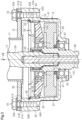
- the housing 18 includes a worm wheel housing member 41 and a worm housing member 42.
- Each of the worm wheel housing member 41 and the worm housing member 42 has a cylindrical shape.
- the worm housing member 42 is coupled to the outer peripheral surface of the worm wheel housing member 41.
- the worm housing member 42 extends in a direction orthogonal to the axis of the worm wheel housing member 41.
- the inside of the worm wheel housing member 41 and the inside of the worm housing member 42 communicate with each other via a communication hole (not shown).
- the worm wheel housing member 41 constitutes a cylindrical portion of the housing 18.
- the housing 18 is made of metal such as aluminum.
- the worm wheel 22 is rotatably housed inside the worm wheel housing member 41.
- the worm 21 is rotatably supported inside the worm housing member 42 via a bearing (not shown).
- the worm wheel 22 and the worm 21 mesh with each other via the communication hole inside the housing 18.
- the worm wheel housing member 41 has an opening 41A at its first end in the axial direction, and has an end wall at its second end opposite to the first end.
- the opening 41A is open to the lower tube 17 along the axis of the worm wheel housing member 41.
- the outside diameter of the worm wheel housing member 41 is substantially the same as the outside diameter of the flange 31.
- the worm wheel housing member 41 includes a cylindrical bearing support portion 43.
- the bearing support portion 43 is provided on the end wall of the worm wheel housing member 41.
- the opening 41A and the bearing support portion 43 are positioned coaxially.
- the inside of the worm wheel housing member 41 and the outside of the worm wheel housing member 41 communicate with each other via the bearing support portion 43.
- the worm wheel housing member 41 includes two tightening portions 44.
- the tightening portions 44 are portions to which the bolts 30 are tightened when fixing the flange 31 to the housing 18.
- the tightening portions 44 protrude radially outward from the outer peripheral surface of the worm wheel housing member 41.
- the two tightening portions 44 are positioned opposite to each other in the radial direction of the worm wheel housing member 41.
- the tightening portions 44 each have a screw hole 44A. End faces of the tightening portions 44 in which the screw holes 44A open are flush with an end face of the worm wheel housing member 41 in which the opening 41A opens.
- the peripheral edge of the flange 31 abuts against the end face of the worm wheel housing member 41 in which the opening 41A opens.
- the insertion hole 31B of the flange 31 and the screw hole 44A of the housing 18 are aligned with each other.
- the bolt 30 is inserted through the insertion hole 31B of the flange 31 from the side opposite to the housing 18.
- the bolt 30 is tightened to the tightening portion 44 of the housing 18.
- the flange 31 is fixed to the housing 18. That is, the lower tube 17 is coupled to the housing 18 via the flange 31.
- the opening 41A of the housing 18 is closed by the flange 31.
- the flange 31 serves also as a cover that closes the opening 41A of the housing 18.
- the worm wheel housing member 41 rotatably supports the inner shaft 12.
- the inner shaft 12 extends through the worm wheel housing member 41.
- the axis of the inner shaft 12 and the axis of the worm wheel housing member 41 are on the same line.
- the inner shaft 12 includes an input shaft 12A, an output shaft 12B, and a torsion bar 12C.
- the input shaft 12A and the output shaft 12B are coupled to each other via the torsion bar 12C.
- the output shaft 12B is a hollow cylinder.
- a first end of the input shaft 12A is coupled to the outer shaft 11.
- a second end of the input shaft 12A is inserted into a first end of the output shaft 12B.
- a clearance is present between the outer peripheral surface of the input shaft 12A and the inner peripheral surface of the output shaft 12B.
- a plain bearing 12D is interposed between the outer peripheral surface of the input shaft 12A and the inner peripheral surface of the output shaft 12B. The input shaft 12A and the output shaft 12B can rotate relative to each other via the plain bearing 12D.
- a first end of the torsion bar 12C is inserted and fixed to the second end of the input shaft 12A.
- a second end of the torsion bar 12C is inserted through the output shaft 12B.
- a clearance is present between the outer peripheral surface of the torsion bar 12C and the inner peripheral surface of the output shaft 12B.
- the second end of the torsion bar 12C is fixed to a second end of the output shaft 12B.
- a steering torque applied to the steering wheel 6 is transmitted to the output shaft 12B via the input shaft 12A and the torsion bar 12C.
- the torsion bar 12C twists depending on the steering torque.
- the worm wheel 22 and a bearing support member 50 are housed inside the worm wheel housing member 41.
- the worm wheel 22 is fixed to the outer peripheral surface of the output shaft 12B so as to be rotatable together.
- the bearing support member 50 has a cylindrical shape and is attached so as to be rotatable relative to the outer peripheral surface of the output shaft 12B.
- the worm wheel 22 and the bearing support member 50 are arranged away from each other along the axial direction of the worm wheel housing member 41.
- the worm wheel 22 is disposed between the bearing support member 50 and the end wall of the worm wheel housing member 41.
- the worm wheel housing member 41, the worm wheel 22, and the bearing support member 50 are positioned coaxially.
- the bearing support member 50 includes a peripheral wall 50A and an end wall 50B extending radially inward from a first end of the peripheral wall 50A in the axial direction.
- the end wall 50B is a wall portion of the bearing support member 50 that extends in the radial direction.
- the peripheral wall 50A has a second end that is an open end opposite to the first end.
- the bearing support member 50 has an insertion hole 51.
- the insertion hole 51 extends through the center of the end wall 50B of the bearing support member 50.
- An annular inward protruding thread 52 is provided on the inner peripheral surface of the end wall 50B.
- the inward protruding thread 52 extends in a circumferential direction along the inner peripheral surface of the bearing support member 50, more specifically, along the inner peripheral surface of the end wall 50B.
- the inward protruding thread 52 is flush with the inner surface of the end wall 50B of the bearing support member 50.
- the bearing support member 50 includes an annular outward protruding thread 53.
- the outward protruding thread 53 is provided at an end of the bearing support member 50 in the axial direction, more specifically, at a second end of the peripheral wall 50A.
- the outward protruding thread 53 extends in the circumferential direction along the outer peripheral surface of the peripheral wall 50A.
- the outward protruding thread 53 is inclined closer to the flange 31 toward the radially outer side of the bearing support member 50.
- the bearing support member 50 is made of, for example, synthetic resin. That is, the linear thermal expansion coefficients of the bearing support member 50 and the housing 18 are different from each other. The linear thermal expansion coefficient of the synthetic resin is larger than the linear thermal expansion coefficient of the metal.
- the outer peripheral surface of the bearing support member 50 that is, the outer peripheral surface of the end wall 50B is fitted to the inner peripheral surface of the worm wheel housing member 41.
- the bearing support member 50 includes a corner 54 formed at an intersection of the end wall 50B and the peripheral wall 50A.
- the corner 54 abuts, in an attachment direction DW, against an annular stepped portion 45 provided on the inner peripheral surface of the worm wheel housing member 41.
- the attachment direction DW is a direction along the axis of the worm wheel housing member 41 and is a direction in which the bearing support member 50 is inserted into the worm wheel housing member 41.
- the stepped portion 45 is provided at a part where the bore diameter of the worm wheel housing member 41 changes, and extends in the circumferential direction along the inner peripheral surface of the worm wheel housing member 41.
- the outward protruding thread 53 is engaged in an annular groove 46 provided on the inner peripheral surface of the worm wheel housing member 41.
- the groove 46 extends in the circumferential direction along the inner peripheral surface of the worm wheel housing member 41.
- the output shaft 12B is supported via a bearing 61 so as to be rotatable relative to the inner peripheral surface of the bearing support portion 43.
- the bearing 61 is in a state in which movement in the axial direction is restricted.
- An annular stepped portion 62 and a snap ring 63 are provided on the outer peripheral surface of the output shaft 12B.
- An inner ring of the bearing 61 is interposed between the stepped portion 62 and the snap ring 63.
- An annular protrusion 64 and a snap ring 65 are provided on the inner peripheral surface of the bearing support portion 43.
- An outer ring of the bearing 61 is interposed between the protrusion 64 and the snap ring 65.
- the output shaft 12B is supported via a bearing 71 so as to be rotatable relative to the insertion hole 51 of the bearing support member 50.
- the bearing 71 is in a state in which movement in the axial direction is restricted.
- An annular protruding thread 72 is provided on the outer peripheral surface of the output shaft 12B.
- An inner ring of the bearing 71 abuts against the protruding thread 72 in the attachment direction DW.
- An outer ring of the bearing 71 abuts against the annular inward protruding thread 52 of the bearing support member 50 in a direction opposite to the attachment direction DW.
- the movement of the bearing support member 50 in the attachment direction DW is restricted by the abutment of the annular inward protruding thread 52 against the outer ring of the bearing 71 in the attachment direction DW as well as the abutment of the corner 54 of the bearing support member 50 against the annular stepped portion 45.
- the internal space of the worm wheel housing member 41 is partitioned into two spaces by the bearing support member 50.
- a sensor 80 is provided in a space between the bearing support member 50 and the flange 31.
- the sensor 80 includes a torque sensor and a rotation angle sensor.
- the torque sensor detects a steering torque based on the amount of twist of the torsion bar 12C.
- the rotation angle sensor detects a rotation angle of the input shaft 12A as a steering angle.
- Grease is sealed in a space between the bearing support member 50 and the end wall of the worm wheel housing member 41.
- the bearing support member 50 has a first slit 55 and a second slit 56.
- the first slit 55 and the second slit 56 are provided in the end wall 50B.
- the first slit 55 and the second slit 56 are provided on a first end face of the end wall 50B in the axial direction.
- the first end face is an end face of the end wall 50B on a side where the peripheral wall 50A protrudes in the axial direction.
- the first end face is orthogonal to the axial direction.
- the first slit 55 and the second slit 56 are annular grooves extending in the circumferential direction.
- the first slit 55 and the second slit 56 are open in a direction opposite to the attachment direction DW of the bearing support member 50.
- the first slit 55 and the second slit 56 are provided concentrically about the axis of the bearing support member 50.
- the first slit 55 is positioned on a radially outer side of the second slit 56.
- the first slit 55 extends in the circumferential direction along the outer peripheral surface of the bearing support member 50.
- the first slit 55 also extends along the inner peripheral surface of the peripheral wall 50A.
- the first slit 55 has annular inner wall surfaces facing each other in the radial direction.
- the radially outer inner wall surface is continuous with the inner peripheral surface of the peripheral wall 50A without any step.
- the second slit 56 is positioned on a radially inner side of the first slit 55.
- the second slit 56 surrounds the insertion hole 51.
- the second slit 56 extends in the circumferential direction along the inner peripheral surface of the insertion hole 51.
- the inner peripheral surface of the insertion hole 51 is also the inner peripheral surface of the bearing support member 50.
- the first slit 55 and the second slit 56 constitute a deformation allowing portion that allows elastic deformation of the bearing support member 50 in the radial direction.
- the bearing support member 50 has a plurality of recesses 57.
- the recesses 57 are provided on a second end face of the end wall 50B in the axial direction.
- the second end face is an end face opposite to the first end face in the axial direction.
- the recesses 57 are provided away from each other in the circumferential direction of the end wall 50B.
- the recesses 57 are positioned in a region between the first slit 55 and the second slit 56 on the second end face when viewed in the axial direction.
- the bearing support member 50 includes a plurality of ribs 58.
- the ribs 58 are for reinforcement. By providing the plurality of recesses 57 in the end wall 50B, the plurality of ribs 58 is provided.
- the rib 58 is a part of the bearing support member 50 between two recesses 57 adjacent in the circumferential direction.
- the rib 58 is a wall extending in the radial direction of the end wall 50B.
- the rib 58 couples a radially outer portion of the end wall 50B where the first slit 55 is provided and a radially inner portion of the end wall 50B where the second slit 56 is provided.
- the thickness of the resin of the bearing support member 50 is substantially uniform.
- the dimensions of each part of the bearing support member 50 are set from the viewpoint of keeping the uniform resin thickness of the bearing support member 50.
- the dimensions of each part include, for example, the following seven dimensions (A1) to (A7).
- the depth is a dimension in the axial direction.
- the width is a dimension in the radial direction.
- the present embodiment has the following effects.
- the present embodiment may be modified as follows.
Landscapes
- Engineering & Computer Science (AREA)
- Chemical & Material Sciences (AREA)
- Combustion & Propulsion (AREA)
- Transportation (AREA)
- Mechanical Engineering (AREA)
- Power Steering Mechanism (AREA)
Applications Claiming Priority (2)
| Application Number | Priority Date | Filing Date | Title |
|---|---|---|---|
| PCT/JP2021/024115 WO2022269899A1 (fr) | 2021-06-25 | 2021-06-25 | Dispositif de direction |
| PCT/JP2022/005174 WO2022269986A1 (fr) | 2021-06-25 | 2022-02-09 | Dispositif de direction |
Publications (2)
| Publication Number | Publication Date |
|---|---|
| EP4360997A1 true EP4360997A1 (fr) | 2024-05-01 |
| EP4360997A4 EP4360997A4 (fr) | 2024-10-23 |
Family
ID=84543734
Family Applications (1)
| Application Number | Title | Priority Date | Filing Date |
|---|---|---|---|
| EP22826644.1A Pending EP4360997A4 (fr) | 2021-06-25 | 2022-02-09 | Dispositif de direction |
Country Status (4)
| Country | Link |
|---|---|
| US (1) | US20240286670A1 (fr) |
| EP (1) | EP4360997A4 (fr) |
| JP (1) | JP7642812B2 (fr) |
| WO (2) | WO2022269899A1 (fr) |
Family Cites Families (6)
| Publication number | Priority date | Publication date | Assignee | Title |
|---|---|---|---|---|
| JP2008184043A (ja) * | 2007-01-30 | 2008-08-14 | Nsk Ltd | 電動パワーステアリング装置およびその製造方法 |
| CN102112363B (zh) * | 2008-08-01 | 2013-07-10 | 株式会社捷太格特 | 电动动力转向装置 |
| EP2913246B1 (fr) * | 2012-10-29 | 2019-03-27 | NSK Ltd. | Dispositif électrique de direction assistée |
| EP2921372A4 (fr) * | 2012-11-15 | 2016-11-02 | Nsk Ltd | Système de direction assistée électrique |
| JP2016211615A (ja) * | 2015-04-30 | 2016-12-15 | 株式会社ジェイテクト | ウォーム減速機およびステアリング装置 |
| JP2020090139A (ja) | 2018-12-04 | 2020-06-11 | 株式会社ジェイテクト | ステアリング装置の制御装置 |
-
2021
- 2021-06-25 WO PCT/JP2021/024115 patent/WO2022269899A1/fr not_active Ceased
-
2022
- 2022-02-09 US US18/571,861 patent/US20240286670A1/en active Pending
- 2022-02-09 JP JP2023529486A patent/JP7642812B2/ja active Active
- 2022-02-09 WO PCT/JP2022/005174 patent/WO2022269986A1/fr not_active Ceased
- 2022-02-09 EP EP22826644.1A patent/EP4360997A4/fr active Pending
Also Published As
| Publication number | Publication date |
|---|---|
| WO2022269986A1 (fr) | 2022-12-29 |
| JP7642812B2 (ja) | 2025-03-10 |
| JPWO2022269986A1 (fr) | 2022-12-29 |
| CN117500716A (zh) | 2024-02-02 |
| WO2022269899A1 (fr) | 2022-12-29 |
| US20240286670A1 (en) | 2024-08-29 |
| EP4360997A4 (fr) | 2024-10-23 |
Similar Documents
| Publication | Publication Date | Title |
|---|---|---|
| US20230011733A1 (en) | Steering actuator apparatus for vehicle | |
| JP5180483B2 (ja) | トルクセンサの製造方法 | |
| US9199662B2 (en) | Rack and pinion steering gear unit | |
| EP3705375B1 (fr) | Carter de boîte de vitesses pour dispositif de direction assistée électrique, son procédé de fabrication, et dispositif de direction assistée électrique | |
| EP3258576B1 (fr) | Actionneur et son procédé de production | |
| US20120067151A1 (en) | Worm drive | |
| EP3324167B1 (fr) | Appareil de détection de couple et son procédé de fabrication | |
| WO2007102558A1 (fr) | Mécanisme de vis d'avance et dispositif de direction | |
| JP5123738B2 (ja) | 電動パワーステアリング装置 | |
| JP5102240B2 (ja) | シール構造 | |
| US7748742B2 (en) | Energy absorbing steering system | |
| EP4360997A1 (fr) | Dispositif de direction | |
| JP7177758B2 (ja) | ステアリング装置 | |
| CN117500716B (zh) | 转向装置 | |
| CN115315383A (zh) | 转向装置 | |
| JP2022099886A (ja) | ウォームホイール、電動パワーステアリング装置、及びウォームホイールの製造方法 | |
| JP5508826B2 (ja) | トルクセンサ | |
| JP5970992B2 (ja) | 電動パワーステアリング装置 | |
| CN118900802B (zh) | 转向装置 | |
| JP2011046310A (ja) | 車両用操舵装置 | |
| KR101922406B1 (ko) | 전동식 조향 장치용 플렉서블 댐퍼 장치 | |
| JPH06239245A (ja) | ラックピニオン式ステアリング装置 | |
| CN112249149A (zh) | 分体式转向机 | |
| EP4408722A1 (fr) | Colonne de direction orientable pour véhicule | |
| JP2024093325A (ja) | ステアリング装置 |
Legal Events
| Date | Code | Title | Description |
|---|---|---|---|
| STAA | Information on the status of an ep patent application or granted ep patent |
Free format text: STATUS: THE INTERNATIONAL PUBLICATION HAS BEEN MADE |
|
| PUAI | Public reference made under article 153(3) epc to a published international application that has entered the european phase |
Free format text: ORIGINAL CODE: 0009012 |
|
| STAA | Information on the status of an ep patent application or granted ep patent |
Free format text: STATUS: REQUEST FOR EXAMINATION WAS MADE |
|
| 17P | Request for examination filed |
Effective date: 20231229 |
|
| AK | Designated contracting states |
Kind code of ref document: A1 Designated state(s): AL AT BE BG CH CY CZ DE DK EE ES FI FR GB GR HR HU IE IS IT LI LT LU LV MC MK MT NL NO PL PT RO RS SE SI SK SM TR |
|
| DAV | Request for validation of the european patent (deleted) | ||
| DAX | Request for extension of the european patent (deleted) | ||
| A4 | Supplementary search report drawn up and despatched |
Effective date: 20240923 |
|
| RIC1 | Information provided on ipc code assigned before grant |
Ipc: B62D 6/10 20060101ALI20240917BHEP Ipc: B62D 5/04 20060101AFI20240917BHEP |
|
| GRAP | Despatch of communication of intention to grant a patent |
Free format text: ORIGINAL CODE: EPIDOSNIGR1 |
|
| STAA | Information on the status of an ep patent application or granted ep patent |
Free format text: STATUS: GRANT OF PATENT IS INTENDED |
|
| INTG | Intention to grant announced |
Effective date: 20251127 |
|
| GRAS | Grant fee paid |
Free format text: ORIGINAL CODE: EPIDOSNIGR3 |
|
| GRAA | (expected) grant |
Free format text: ORIGINAL CODE: 0009210 |
|
| STAA | Information on the status of an ep patent application or granted ep patent |
Free format text: STATUS: THE PATENT HAS BEEN GRANTED |
|
| RAP1 | Party data changed (applicant data changed or rights of an application transferred) |
Owner name: JTEKT CORPORATION |
|
| RIN1 | Information on inventor provided before grant (corrected) |
Inventor name: KAWAMURA, NAOFUMI Inventor name: SUZUKI, HIROAKI Inventor name: EBISU, TETSUYA Inventor name: FUJIOKA, YUKI Inventor name: SUGIURA, TOMONORI Inventor name: ITO, KOSUKE Inventor name: BAITO, TAKAHIRO Inventor name: NAKAAKI, TAKAO Inventor name: MURAKAMI, YOSHIAKI Inventor name: ASAKAWA, KAZUHISA |