EP4361492B1 - Dispositif de stockage de fluide cryogénique - Google Patents
Dispositif de stockage de fluide cryogénique Download PDFInfo
- Publication number
- EP4361492B1 EP4361492B1 EP23187161.7A EP23187161A EP4361492B1 EP 4361492 B1 EP4361492 B1 EP 4361492B1 EP 23187161 A EP23187161 A EP 23187161A EP 4361492 B1 EP4361492 B1 EP 4361492B1
- Authority
- EP
- European Patent Office
- Prior art keywords
- wall
- joining portion
- tank
- welded
- volume
- Prior art date
- Legal status (The legal status is an assumption and is not a legal conclusion. Google has not performed a legal analysis and makes no representation as to the accuracy of the status listed.)
- Active
Links
Images
Classifications
-
- F—MECHANICAL ENGINEERING; LIGHTING; HEATING; WEAPONS; BLASTING
- F17—STORING OR DISTRIBUTING GASES OR LIQUIDS
- F17C—VESSELS FOR CONTAINING OR STORING COMPRESSED, LIQUEFIED OR SOLIDIFIED GASES; FIXED-CAPACITY GAS-HOLDERS; FILLING VESSELS WITH, OR DISCHARGING FROM VESSELS, COMPRESSED, LIQUEFIED, OR SOLIDIFIED GASES
- F17C3/00—Vessels not under pressure
-
- F—MECHANICAL ENGINEERING; LIGHTING; HEATING; WEAPONS; BLASTING
- F17—STORING OR DISTRIBUTING GASES OR LIQUIDS
- F17C—VESSELS FOR CONTAINING OR STORING COMPRESSED, LIQUEFIED OR SOLIDIFIED GASES; FIXED-CAPACITY GAS-HOLDERS; FILLING VESSELS WITH, OR DISCHARGING FROM VESSELS, COMPRESSED, LIQUEFIED, OR SOLIDIFIED GASES
- F17C2201/00—Vessel construction, in particular geometry, arrangement or size
- F17C2201/01—Shape
- F17C2201/0104—Shape cylindrical
- F17C2201/0109—Shape cylindrical with exteriorly curved end-piece
-
- F—MECHANICAL ENGINEERING; LIGHTING; HEATING; WEAPONS; BLASTING
- F17—STORING OR DISTRIBUTING GASES OR LIQUIDS
- F17C—VESSELS FOR CONTAINING OR STORING COMPRESSED, LIQUEFIED OR SOLIDIFIED GASES; FIXED-CAPACITY GAS-HOLDERS; FILLING VESSELS WITH, OR DISCHARGING FROM VESSELS, COMPRESSED, LIQUEFIED, OR SOLIDIFIED GASES
- F17C2201/00—Vessel construction, in particular geometry, arrangement or size
- F17C2201/05—Size
- F17C2201/056—Small (<1 m3)
-
- F—MECHANICAL ENGINEERING; LIGHTING; HEATING; WEAPONS; BLASTING
- F17—STORING OR DISTRIBUTING GASES OR LIQUIDS
- F17C—VESSELS FOR CONTAINING OR STORING COMPRESSED, LIQUEFIED OR SOLIDIFIED GASES; FIXED-CAPACITY GAS-HOLDERS; FILLING VESSELS WITH, OR DISCHARGING FROM VESSELS, COMPRESSED, LIQUEFIED, OR SOLIDIFIED GASES
- F17C2201/00—Vessel construction, in particular geometry, arrangement or size
- F17C2201/05—Size
- F17C2201/058—Size portable (<30 l)
-
- F—MECHANICAL ENGINEERING; LIGHTING; HEATING; WEAPONS; BLASTING
- F17—STORING OR DISTRIBUTING GASES OR LIQUIDS
- F17C—VESSELS FOR CONTAINING OR STORING COMPRESSED, LIQUEFIED OR SOLIDIFIED GASES; FIXED-CAPACITY GAS-HOLDERS; FILLING VESSELS WITH, OR DISCHARGING FROM VESSELS, COMPRESSED, LIQUEFIED, OR SOLIDIFIED GASES
- F17C2203/00—Vessel construction, in particular walls or details thereof
- F17C2203/03—Thermal insulations
- F17C2203/0391—Thermal insulations by vacuum
-
- F—MECHANICAL ENGINEERING; LIGHTING; HEATING; WEAPONS; BLASTING
- F17—STORING OR DISTRIBUTING GASES OR LIQUIDS
- F17C—VESSELS FOR CONTAINING OR STORING COMPRESSED, LIQUEFIED OR SOLIDIFIED GASES; FIXED-CAPACITY GAS-HOLDERS; FILLING VESSELS WITH, OR DISCHARGING FROM VESSELS, COMPRESSED, LIQUEFIED, OR SOLIDIFIED GASES
- F17C2203/00—Vessel construction, in particular walls or details thereof
- F17C2203/06—Materials for walls or layers thereof; Properties or structures of walls or their materials
- F17C2203/0602—Wall structures; Special features thereof
- F17C2203/0612—Wall structures
- F17C2203/0626—Multiple walls
- F17C2203/0629—Two walls
-
- F—MECHANICAL ENGINEERING; LIGHTING; HEATING; WEAPONS; BLASTING
- F17—STORING OR DISTRIBUTING GASES OR LIQUIDS
- F17C—VESSELS FOR CONTAINING OR STORING COMPRESSED, LIQUEFIED OR SOLIDIFIED GASES; FIXED-CAPACITY GAS-HOLDERS; FILLING VESSELS WITH, OR DISCHARGING FROM VESSELS, COMPRESSED, LIQUEFIED, OR SOLIDIFIED GASES
- F17C2203/00—Vessel construction, in particular walls or details thereof
- F17C2203/06—Materials for walls or layers thereof; Properties or structures of walls or their materials
- F17C2203/0634—Materials for walls or layers thereof
- F17C2203/0636—Metals
- F17C2203/0639—Steels
- F17C2203/0643—Stainless steels
-
- F—MECHANICAL ENGINEERING; LIGHTING; HEATING; WEAPONS; BLASTING
- F17—STORING OR DISTRIBUTING GASES OR LIQUIDS
- F17C—VESSELS FOR CONTAINING OR STORING COMPRESSED, LIQUEFIED OR SOLIDIFIED GASES; FIXED-CAPACITY GAS-HOLDERS; FILLING VESSELS WITH, OR DISCHARGING FROM VESSELS, COMPRESSED, LIQUEFIED, OR SOLIDIFIED GASES
- F17C2203/00—Vessel construction, in particular walls or details thereof
- F17C2203/06—Materials for walls or layers thereof; Properties or structures of walls or their materials
- F17C2203/0634—Materials for walls or layers thereof
- F17C2203/0636—Metals
- F17C2203/0646—Aluminium
-
- F—MECHANICAL ENGINEERING; LIGHTING; HEATING; WEAPONS; BLASTING
- F17—STORING OR DISTRIBUTING GASES OR LIQUIDS
- F17C—VESSELS FOR CONTAINING OR STORING COMPRESSED, LIQUEFIED OR SOLIDIFIED GASES; FIXED-CAPACITY GAS-HOLDERS; FILLING VESSELS WITH, OR DISCHARGING FROM VESSELS, COMPRESSED, LIQUEFIED, OR SOLIDIFIED GASES
- F17C2203/00—Vessel construction, in particular walls or details thereof
- F17C2203/06—Materials for walls or layers thereof; Properties or structures of walls or their materials
- F17C2203/0634—Materials for walls or layers thereof
- F17C2203/0636—Metals
- F17C2203/0648—Alloys or compositions of metals
-
- F—MECHANICAL ENGINEERING; LIGHTING; HEATING; WEAPONS; BLASTING
- F17—STORING OR DISTRIBUTING GASES OR LIQUIDS
- F17C—VESSELS FOR CONTAINING OR STORING COMPRESSED, LIQUEFIED OR SOLIDIFIED GASES; FIXED-CAPACITY GAS-HOLDERS; FILLING VESSELS WITH, OR DISCHARGING FROM VESSELS, COMPRESSED, LIQUEFIED, OR SOLIDIFIED GASES
- F17C2205/00—Vessel construction, in particular mounting arrangements, attachments or identifications means
- F17C2205/01—Mounting arrangements
- F17C2205/0123—Mounting arrangements characterised by number of vessels
- F17C2205/0126—One vessel
-
- F—MECHANICAL ENGINEERING; LIGHTING; HEATING; WEAPONS; BLASTING
- F17—STORING OR DISTRIBUTING GASES OR LIQUIDS
- F17C—VESSELS FOR CONTAINING OR STORING COMPRESSED, LIQUEFIED OR SOLIDIFIED GASES; FIXED-CAPACITY GAS-HOLDERS; FILLING VESSELS WITH, OR DISCHARGING FROM VESSELS, COMPRESSED, LIQUEFIED, OR SOLIDIFIED GASES
- F17C2205/00—Vessel construction, in particular mounting arrangements, attachments or identifications means
- F17C2205/03—Fluid connections, filters, valves, closure means or other attachments
- F17C2205/0302—Fittings, valves, filters, or components in connection with the gas storage device
- F17C2205/0308—Protective caps
-
- F—MECHANICAL ENGINEERING; LIGHTING; HEATING; WEAPONS; BLASTING
- F17—STORING OR DISTRIBUTING GASES OR LIQUIDS
- F17C—VESSELS FOR CONTAINING OR STORING COMPRESSED, LIQUEFIED OR SOLIDIFIED GASES; FIXED-CAPACITY GAS-HOLDERS; FILLING VESSELS WITH, OR DISCHARGING FROM VESSELS, COMPRESSED, LIQUEFIED, OR SOLIDIFIED GASES
- F17C2205/00—Vessel construction, in particular mounting arrangements, attachments or identifications means
- F17C2205/03—Fluid connections, filters, valves, closure means or other attachments
- F17C2205/0302—Fittings, valves, filters, or components in connection with the gas storage device
- F17C2205/0323—Valves
-
- F—MECHANICAL ENGINEERING; LIGHTING; HEATING; WEAPONS; BLASTING
- F17—STORING OR DISTRIBUTING GASES OR LIQUIDS
- F17C—VESSELS FOR CONTAINING OR STORING COMPRESSED, LIQUEFIED OR SOLIDIFIED GASES; FIXED-CAPACITY GAS-HOLDERS; FILLING VESSELS WITH, OR DISCHARGING FROM VESSELS, COMPRESSED, LIQUEFIED, OR SOLIDIFIED GASES
- F17C2209/00—Vessel construction, in particular methods of manufacturing
- F17C2209/22—Assembling processes
- F17C2209/221—Welding
-
- F—MECHANICAL ENGINEERING; LIGHTING; HEATING; WEAPONS; BLASTING
- F17—STORING OR DISTRIBUTING GASES OR LIQUIDS
- F17C—VESSELS FOR CONTAINING OR STORING COMPRESSED, LIQUEFIED OR SOLIDIFIED GASES; FIXED-CAPACITY GAS-HOLDERS; FILLING VESSELS WITH, OR DISCHARGING FROM VESSELS, COMPRESSED, LIQUEFIED, OR SOLIDIFIED GASES
- F17C2221/00—Handled fluid, in particular type of fluid
- F17C2221/01—Pure fluids
- F17C2221/012—Hydrogen
-
- F—MECHANICAL ENGINEERING; LIGHTING; HEATING; WEAPONS; BLASTING
- F17—STORING OR DISTRIBUTING GASES OR LIQUIDS
- F17C—VESSELS FOR CONTAINING OR STORING COMPRESSED, LIQUEFIED OR SOLIDIFIED GASES; FIXED-CAPACITY GAS-HOLDERS; FILLING VESSELS WITH, OR DISCHARGING FROM VESSELS, COMPRESSED, LIQUEFIED, OR SOLIDIFIED GASES
- F17C2223/00—Handled fluid before transfer, i.e. state of fluid when stored in the vessel or before transfer from the vessel
- F17C2223/01—Handled fluid before transfer, i.e. state of fluid when stored in the vessel or before transfer from the vessel characterised by the phase
- F17C2223/0146—Two-phase
- F17C2223/0153—Liquefied gas, e.g. LPG, GPL
- F17C2223/0161—Liquefied gas, e.g. LPG, GPL cryogenic, e.g. LNG, GNL, PLNG
-
- F—MECHANICAL ENGINEERING; LIGHTING; HEATING; WEAPONS; BLASTING
- F17—STORING OR DISTRIBUTING GASES OR LIQUIDS
- F17C—VESSELS FOR CONTAINING OR STORING COMPRESSED, LIQUEFIED OR SOLIDIFIED GASES; FIXED-CAPACITY GAS-HOLDERS; FILLING VESSELS WITH, OR DISCHARGING FROM VESSELS, COMPRESSED, LIQUEFIED, OR SOLIDIFIED GASES
- F17C2223/00—Handled fluid before transfer, i.e. state of fluid when stored in the vessel or before transfer from the vessel
- F17C2223/03—Handled fluid before transfer, i.e. state of fluid when stored in the vessel or before transfer from the vessel characterised by the pressure level
- F17C2223/033—Small pressure, e.g. for liquefied gas
-
- F—MECHANICAL ENGINEERING; LIGHTING; HEATING; WEAPONS; BLASTING
- F17—STORING OR DISTRIBUTING GASES OR LIQUIDS
- F17C—VESSELS FOR CONTAINING OR STORING COMPRESSED, LIQUEFIED OR SOLIDIFIED GASES; FIXED-CAPACITY GAS-HOLDERS; FILLING VESSELS WITH, OR DISCHARGING FROM VESSELS, COMPRESSED, LIQUEFIED, OR SOLIDIFIED GASES
- F17C2227/00—Transfer of fluids, i.e. method or means for transferring the fluid; Heat exchange with the fluid
- F17C2227/03—Heat exchange with the fluid
- F17C2227/0367—Localisation of heat exchange
- F17C2227/0369—Localisation of heat exchange in or on a vessel
- F17C2227/0376—Localisation of heat exchange in or on a vessel in wall contact
- F17C2227/0383—Localisation of heat exchange in or on a vessel in wall contact outside the vessel
-
- F—MECHANICAL ENGINEERING; LIGHTING; HEATING; WEAPONS; BLASTING
- F17—STORING OR DISTRIBUTING GASES OR LIQUIDS
- F17C—VESSELS FOR CONTAINING OR STORING COMPRESSED, LIQUEFIED OR SOLIDIFIED GASES; FIXED-CAPACITY GAS-HOLDERS; FILLING VESSELS WITH, OR DISCHARGING FROM VESSELS, COMPRESSED, LIQUEFIED, OR SOLIDIFIED GASES
- F17C2260/00—Purposes of gas storage and gas handling
- F17C2260/01—Improving mechanical properties or manufacturing
- F17C2260/012—Reducing weight
-
- F—MECHANICAL ENGINEERING; LIGHTING; HEATING; WEAPONS; BLASTING
- F17—STORING OR DISTRIBUTING GASES OR LIQUIDS
- F17C—VESSELS FOR CONTAINING OR STORING COMPRESSED, LIQUEFIED OR SOLIDIFIED GASES; FIXED-CAPACITY GAS-HOLDERS; FILLING VESSELS WITH, OR DISCHARGING FROM VESSELS, COMPRESSED, LIQUEFIED, OR SOLIDIFIED GASES
- F17C2260/00—Purposes of gas storage and gas handling
- F17C2260/03—Dealing with losses
- F17C2260/031—Dealing with losses due to heat transfer
- F17C2260/032—Avoiding freezing or defrosting
Definitions
- the invention relates to a device for storing cryogenic fluid, for example for storing liquefied hydrogen.
- the invention relates more particularly to a device for storing cryogenic fluid in accordance with the preamble of claim 1.
- the invention relates in particular to a vacuum insulated tank for cryogenic fluids (typically liquid hydrogen) provided with an equipment housing (sometimes called a "valve box").
- This housing or “valve box” is a part of the cryogenic tank which contains all or part of the components associated with the storage (valve(s), heat exchanger(s), safety device(s), etc.). These components generally require thermal insulation, preferably of the vacuum type.
- valve box is usually made of the same material as the tank's outer shell. This allows the valve box shell to be directly connected to the tank wall, for example by welding. In the case of a stainless steel outer shell, the valve box is made of the same material and assembly is simple to implement. However, this solution leads to a tank with a relatively high mass.
- An aim of the present invention is to overcome all or part of the drawbacks of the prior art noted above.
- the device according to the invention is essentially characterized in that the first wall (3) is made of aluminum alloy and in that the junction portion (5) is composed of an alloy based on aluminum and stainless steel.
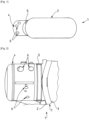
- the illustrated cryogenic fluid storage device 1 comprises a first wall 2 made of aluminum alloy delimiting a tank and a second wall 4 delimiting an adjacent volume or housing intended to house a set of tank equipment, for example at least one valve, at least one heat exchanger, circuitry, etc.
- the tank and the adjacent housing each have a generally cylindrical shape with a circular section.
- any other shape is possible for one or both containers.
- the first wall 2 is for example the outer casing of the tank and is arranged around a third wall 3 delimiting the storage volume for cryogenic fluid.
- the first wall 2 is arranged for example around the third wall 3 with a thermally insulated spacing 7, preferably under vacuum, so that the tank is of the double-walled type 2, 3.
- the second wall 4 is made of stainless steel and is welded to the first wall 2 via a joining portion 5 composed of an alloy based on an aluminum alloy and stainless steel and interposed between the two walls 2, 4.
- this structure provides a bi-material type junction (typically comprising an aluminum alloy and a stainless steel alloy).
- This junction portion 5 can be obtained for example by explosion or diffusion welding.
- This arrangement makes it possible to provide a stainless steel valve box, capable of integrating all or part of the bulkhead crossings (fluidic and/or electrical) more satisfactorily than with an aluminum wall, and which is reliably assembled to a tank wall 2 made of aluminum alloy.
- the second wall 4 can thus include passages 6 symbolized by holes in the schematic representations configured to allow the sealed crossing of the second wall (passage of cables and/or pipes, etc.).
- the second wall 4 and the first wall 2 can be welded respectively at two ends of the joining portion 5. That is to say that the assembly can be carried out via a stainless steel to stainless steel weld then aluminum to aluminum.
- the portions of the second wall 4 and of the first wall 2 welded respectively at two ends of the joining portion 5 may be thinned relative to the joining portion 5 and/or relative to the rest of the walls 4, 2.
- the joining portion has a central thickness of the order of 10 mm while its edges welded to the walls have a lower thickness, for example of the order of 1 to 2 mm.
- the joining portion 5 may have the general shape of a ring.
- the first wall 2 and the second wall 4 may each comprise a tubular end welded to a circumference of the ring formed by the joining portion 5.
- first wall 2 and/or the second wall 4 has a generally cylindrical shape.
- the welded end of the first wall 2 may in particular be at the level of a cylindrical connection attached to the first wall 2.
- the volume delimited by the second wall 4 is under vacuum and for example communicates with the spacing 7, for example by an orifice or passage (and therefore preferably shares the same vacuum).
Landscapes
- Engineering & Computer Science (AREA)
- Mechanical Engineering (AREA)
- General Engineering & Computer Science (AREA)
- Filling Or Discharging Of Gas Storage Vessels (AREA)
Description
- L'invention concerne un dispositif de stockage de fluide cryogénique, par exemple pour le stockage d'hydrogène liquéfié.
- Un tel dispositif est connue de
US 2020/047852 A1 . - L'invention concerne plus particulièrement un dispositif de stockage de fluide cryogénique conformément au préambule de la revendication1.
- L'invention concerne en particulier un réservoir isolé sous vide pour des fluides cryogéniques (typiquement de l'hydrogène liquide) muni d'un boîtier d'équipements (appelé parfois "boite à vanne"). Ce boîtier ou "boite à vanne" est une partie du réservoir cryogénique qui contient tout ou partie des composants annexes au stockage (vanne(s), échangeur(s) de chaleur, dispositif(s) de sécurité, etc.). Ces composants nécessitent généralement de bénéficier d'une isolation thermique de préférence de type sous vide.
- Cette boîte à vanne est habituellement composée du même matériau que l'enveloppe externe du réservoir. Ceci permet de pouvoir lier directement l'enveloppe de la boîte à vanne avec la paroi du réservoir, par soudage par exemple. Dans le cadre d'une enveloppe externe en acier inoxydable, la boîte à vanne réalisée dans le même matériau et l'assemblage est simple à mettre en œuvre. Cette solution conduit cependant à un réservoir de masse relativement importante.
- Dans le cas d'un réservoir plus léger, par exemple en alliage d'aluminium par exemple, la réalisation de l'enveloppe de la boîte à vanne en aluminium pose des problèmes. Compte tenu du grand nombre de traversées (orifices de passage) de la paroi de ce boîtier, les soudures aluminium, moins fiables que des soudures en alliage d'acier inoxydable, peuvent être défectueuses. Le réservoir cryogénique étant généralement doté d'une isolation sous vide statique, une liaison vissée entre l'enveloppe extérieure du réservoir et l'enveloppe de la boîte à vanne est risquée.
- Pour cette raison, dans le cas d'un réservoir en alliage d'aluminium, les équipements habituellement présents dans une boîte à vannes ne sont pas intégrés dans un tel boîtier. Dans ce cas, les équipements sont alors mal ou pas isolés thermiquement et sujets à la condensation (d'eau ou d'air). Ceci peut poser des problèmes d'exploitation ou de sécurité.
- Un but de la présente invention est de pallier tout ou partie des inconvénients de l'art antérieur relevés ci-dessus.
- A cette fin, le dispositif selon l'invention, par ailleurs conforme à la définition générique qu'en donne le préambule de la revendication 1, est essentiellement caractérisé en ce que la première paroi (3) est en alliage d'aluminium et en ce que la portion de jonction (5) est composée d'un alliage à base d'aluminium et d'acier inoxydable.
- Par ailleurs, des modes de réalisation de l'invention peuvent comporter l'une ou plusieurs des caractéristiques suivantes :
- la seconde paroi et la première paroi sont soudées respectivement au niveau de deux extrémités de la portion de jonction,
- les portions de la seconde paroi et de la première paroi soudées respectivement au niveau de deux extrémités de la portion de jonction sont amincies relativement à la portion de jonction et/ou relativement au reste des parois,
- la portion de jonction a la forme d'une bague, la première paroi et la seconde paroi comprenant chacune une portion tubulaire dont une extrémité circulaire est soudée sur la circonférence de la bague formée par la portion de jonction,
- la première paroi et/ou la seconde paroi a une forme générale cylindrique,
- la portion soudée de la première paroi et/ou la seconde paroi est située au niveau d'un piquage cylindrique solidaire de la paroi,
- le volume délimité par la seconde paroi abrite au moins l'un parmi, au moins une vanne, un échangeur de chaleur, une portion de conduite, un appareillage électrique, une portion de tuyauterie,
- la seconde paroi comprend au moins un passage configuré pour la traversée de la seconde paroi par un ou des équipement(s),
- le dispositif comprend une troisième paroi délimitant un volume de stockage pour du fluide cryogénique, la première paroi étant disposée autour de la troisième paroi avec un espacement isolé thermiquement de sorte que le réservoir est du type à double parois,
- l'espacement entre la première et la troisième paroi est sous vide,
- le volume délimité par la seconde paroi est sous vide et communique avec l'espacement.
- L'invention peut concerner également tout dispositif ou procédé alternatif comprenant toute combinaison des caractéristiques ci-dessus ou ci-dessous dans le cadre des revendications. D'autres particularités et avantages apparaîtront à la lecture de la description ci-après, faite en référence aux figures dans lesquelles :
- L'invention sera mieux comprise à la lecture de la description qui va suivre donnée uniquement à titre d'exemple et faite en se référant aux dessins annexés dans lesquels :
- [
Fig. 1 ] est une vue schématique et partielle, de côté, d'un exemple de dispositif de stockage selon l'invention, - [
Fig. 2 ] est une vue schématique et partiellement en coupe, d'un détail d'un autre mode de réalisation du dispositif selon l'invention. - Sur toutes les figures, les mêmes références se rapportent aux mêmes éléments.
- Dans cette description détaillée, les réalisations suivantes sont des exemples. Bien que la description se réfère à un ou plusieurs modes de réalisation, cela ne signifie pas que les caractéristiques s'appliquent seulement à un seul mode de réalisation. De simples caractéristiques de différents modes de réalisation peuvent également être combinées et/ou interchangées pour fournir d'autres réalisations.
- Le dispositif 1 de stockage de fluide cryogénique illustré comprend une première paroi 2 en alliage d'aluminium délimitant un réservoir et une seconde paroi 4 délimitant un volume ou boîtier adjacent prévu pour abriter un ensemble d'équipements du réservoir, par exemple au moins une vanne, au moins un échangeur de chaleur, de la circuiterie, ...
- Dans l'exemple de la [
Fig. 1 ], le réservoir et le boîtier adjacent ont chacun une forme générale cylindrique à section circulaire. Bien entendu, tout autre forme est envisageable pour l'un ou les deux contenants. - La première paroi 2 est par exemple l'enveloppe extérieure du réservoir et est disposée autour d'une troisième paroi 3 délimitant le volume de stockage pour du fluide cryogénique. La première paroi 2 est disposée par exemple autour de la troisième paroi 3 avec un espacement 7 isolé thermiquement, de préférence sous vide, de sorte que le réservoir est du type à double parois 2, 3. La seconde paroi 4 est en acier inoxydable et est soudée à la première paroi 2 via une portion 5 de jonction composée d'un alliage à base d'alliage d'aluminium et d'acier inoxydable et interposée entre les deux parois 2, 4.
- C'est-à-dire que cette structure prévoit une jonction de type bi-matière (typiquement comprenant un alliage d'aluminium et un alliage d'acier inoxydable). Cette portion 5 de jonction peut être obtenue par exemple par soudage par explosion ou par diffusion.
- Cet arrangement permet de prévoir une boîte à vanne en acier inoxydable, apte à intégrer tout ou partie des traversées de cloisons (fluidiques et/ou électriques) de manière plus satisfaisante qu'avec une paroi aluminium, et qui est assemblée de façon fiable à une paroi 2 de réservoir en alliage d'aluminium. La seconde paroi 4 peut ainsi comporter des passages 6 symbolisés par des orifices dans les représentations schématiques configurés pour permettre la traversée étanche de la seconde paroi (passage de câbles et/ou conduites...).
- La seconde paroi 4 et la première paroi 2 peuvent être soudées respectivement au niveau de deux extrémités de la portion 5 de jonction. C'est-à-dire que l'assemblage peut être réalisé via une soudure acier inoxydable avec acier inoxydable puis aluminium avec aluminium.
- Comme visible à la [
Fig. 2 ], les portions de la seconde paroi 4 et de la première paroi 2 soudées respectivement au niveau de deux extrémités de la portion 5 de jonction peuvent être amincies relativement à la portion 5 de jonction et/ou relativement au reste des parois 4, 2. Par exemple la portion de jonction a une épaisseur centrale de l'ordre de 10 mm tandis que ses bordures soudées aux parois ont une épaisseur inférieure, par exemple de l'ordre de 1 à 2 mm. - La portion 5 de jonction peut avoir la forme générale d'une bague. La première paroi 2 et la seconde paroi 4 peuvent comprendre chacune une extrémité tubulaire soudée sur une circonférence de la bague formée par la portion 5 de jonction.
- Par exemple, la première paroi 2 et/ou la seconde paroi 4 a une forme générale cylindrique.
- L'extrémité soudée de la première paroi 2 peut en particulier être au niveau d'un piquage cylindrique solidaire rapportée sur la première paroi 2.
- De préférence le volume délimité par la seconde paroi 4 est sous vide et par exemple communique avec l'espacement 7, par exemple par un orifice ou passage (et donc partage de préférence le même vide).
Claims (11)
- Dispositif de stockage de fluide cryogénique comprenant une première paroi (2) formant un réservoir et une seconde paroi (4) délimitant un volume prévu pour abriter un ensemble d'équipements du réservoir, par exemple au moins une vanne, la seconde paroi (4) étant fixée à la première paroi par soudage, la seconde paroi (4) étant en acier inoxydable et le soudage de la seconde paroi (4) à la première paroi (2) étant réalisé via une portion (5) de jonction interposée entre les deux parois (2,4), caractérisé en ce que la première paroi (3) est en alliage d'aluminium et en ce que la portion de jonction (5) est composée d'un alliage à base d'aluminium et d'acier inoxydable.
- Dispositif selon la revendication 1, caractérisé en ce que la seconde paroi (4) et la première paroi (2) sont soudées respectivement au niveau de deux extrémités de la portion (5) de jonction.
- Dispositif selon la revendication 2, caractérisé en ce que les portions de la seconde paroi (4) et de la première paroi (2) soudées respectivement au niveau de deux extrémités de la portion (5) de jonction sont amincies relativement à la portion (5) de jonction et/ou relativement au reste des parois (4, 2).
- Dispositif selon l'une quelconque des revendications 1 à 3, caractérisé en ce que la portion (5) de jonction a la forme d'une bague et en ce que la première paroi (2) et la seconde paroi (4) comprennent chacune une portion tubulaire dont une extrémité circulaire est soudée sur la circonférence de la bague formée par la portion (5) de jonction.
- Dispositif selon l'une quelconque des revendications 1 à 4, caractérisé en ce que la première paroi (2) et/ou la seconde paroi (4) a une forme générale cylindrique.
- Dispositif selon l'une quelconque des revendications 1 à 5, caractérisé en ce que la portion soudée de la première paroi (2) et/ou la seconde paroi (4) est située au niveau d'un piquage cylindrique solidaire de la paroi (2, 4).
- Dispositif selon l'une quelconque des revendications 1 à 6, caractérisé en ce que le volume délimité par la seconde paroi (4) abrite au moins l'un des équipements suivants faisant partie du dispositif de stockage : au moins une vanne, un échangeur de chaleur, une portion de conduite, un appareillage électrique, une portion de tuyauterie.
- Dispositif selon l'une quelconque des revendications 1 à 7, caractérisé en ce que la seconde paroi (4) comprend au moins un passage (6) configuré pour la traversée de la seconde paroi par un ou des équipement(s).
- Dispositif selon l'une quelconque des revendications 1 à 8, caractérisé en ce qu'il comprend une troisième paroi (3) délimitant un volume de stockage pour du fluide cryogénique et en ce que la première paroi (2) est disposée autour de la troisième paroi (3) avec un espacement (7) isolé thermiquement de sorte que le réservoir est du type à double parois (2, 3).
- Dispositif selon la revendication 9, caractérisé en ce que l'espacement (7) entre la première (2) et la troisième (3) paroi est sous vide.
- Dispositif selon la revendication 10, caractérisé en ce que le volume délimité par la seconde paroi (4) est sous vide et communique avec l'espacement (7).
Applications Claiming Priority (1)
| Application Number | Priority Date | Filing Date | Title |
|---|---|---|---|
| FR2211045A FR3141228B1 (fr) | 2022-10-25 | 2022-10-25 | Dispositif de stockage de fluide cryogénique |
Publications (2)
| Publication Number | Publication Date |
|---|---|
| EP4361492A1 EP4361492A1 (fr) | 2024-05-01 |
| EP4361492B1 true EP4361492B1 (fr) | 2025-04-23 |
Family
ID=85018615
Family Applications (1)
| Application Number | Title | Priority Date | Filing Date |
|---|---|---|---|
| EP23187161.7A Active EP4361492B1 (fr) | 2022-10-25 | 2023-07-24 | Dispositif de stockage de fluide cryogénique |
Country Status (2)
| Country | Link |
|---|---|
| EP (1) | EP4361492B1 (fr) |
| FR (1) | FR3141228B1 (fr) |
Families Citing this family (1)
| Publication number | Priority date | Publication date | Assignee | Title |
|---|---|---|---|---|
| CN121346155B (zh) * | 2025-12-17 | 2026-03-17 | 中船双瑞(洛阳)特种装备股份有限公司 | 一种充装高压氧气用气瓶及其制造方法 |
Citations (1)
| Publication number | Priority date | Publication date | Assignee | Title |
|---|---|---|---|---|
| US11807340B2 (en) * | 2017-02-06 | 2023-11-07 | Wärtsilä Finland Oy | Fuel tank arrangement in a marine vessel |
Family Cites Families (5)
| Publication number | Priority date | Publication date | Assignee | Title |
|---|---|---|---|---|
| US3132762A (en) * | 1960-06-09 | 1964-05-12 | Union Carbide Corp | Apparatus for dispensing liquefied gases |
| US4149388A (en) * | 1977-04-25 | 1979-04-17 | Schneider Richard N | Portable cryogenic power system for pneumatically operated tools |
| US6279326B1 (en) * | 1999-10-29 | 2001-08-28 | L'air Liquide, Societe Anonyme Pour L'etude Et L'exploitation Des Procedes Georges Claude | Transportable device for storing and supplying cryogenic fluid, more particularly medical oxygen |
| WO2015040268A1 (fr) * | 2013-09-20 | 2015-03-26 | Wärtsilä Finland Oy | Nouveau dispositif d'accès à un compartiment de stockage de carburant de gaz naturel liquéfié (gnl) |
| FR3094070B1 (fr) * | 2019-03-21 | 2021-10-15 | Air Liquide | Dispositif et procédé de stockage et de fourniture de carburant fluide. |
-
2022
- 2022-10-25 FR FR2211045A patent/FR3141228B1/fr active Active
-
2023
- 2023-07-24 EP EP23187161.7A patent/EP4361492B1/fr active Active
Patent Citations (1)
| Publication number | Priority date | Publication date | Assignee | Title |
|---|---|---|---|---|
| US11807340B2 (en) * | 2017-02-06 | 2023-11-07 | Wärtsilä Finland Oy | Fuel tank arrangement in a marine vessel |
Also Published As
| Publication number | Publication date |
|---|---|
| FR3141228A1 (fr) | 2024-04-26 |
| FR3141228B1 (fr) | 2024-09-27 |
| EP4361492A1 (fr) | 2024-05-01 |
Similar Documents
| Publication | Publication Date | Title |
|---|---|---|
| EP4174357B1 (fr) | Ensemble de connexion optimisé entre deux portions d'une canalisation pour le transport d'un fluide cryogénique, comprenant une chambre d'isolation thermique additionnelle et une chambre d'expansion de fluide | |
| EP2137477B1 (fr) | Échangeur de chaleur pour gaz | |
| EP4361492A1 (fr) | Dispositif de stockage de fluide cryogénique | |
| EP1001239A1 (fr) | Echangeur de chaleur à faisceau de tubes contenu dans un boítier cylindrique | |
| EP2912396A2 (fr) | Échangeur thermique, notamment pour vehicule automobile | |
| EP0895017A1 (fr) | Réservoir pour fluide sous pression | |
| FR2923594A1 (fr) | Dispositif de refroidissement d'un fluide caloporteur | |
| FR2921996A1 (fr) | Dispositif de jonction isolee entre deux troncons de tuyau double enveloppe | |
| EP4083489B1 (fr) | Connecteur | |
| EP4382433B1 (fr) | Aéronef comprenant au moins un dispositif d'alimentation en hydrogène comprenant un réservoir d'hydrogène ainsi que des équipements répartis dans au moins un contenant relié au réservoir et au moins un contenant amovible | |
| WO2021255000A1 (fr) | Dôme liquide d'une cuve de stockage pour gaz liquéfié | |
| FR2892803A1 (fr) | Boite collectrice pour echangeur de chaleur, notamment pour evaporateur de climatisation, echangeur comportant une telle boite | |
| FR2661489A1 (fr) | Dispositif de boite a eau et de vase d'expansion pour un echangeur de chaleur, tel qu'un radiateur de refroidissement, et echangeur de chaleur comprenant ce dispositif. | |
| WO2021254999A1 (fr) | Dôme liquide d'une cuve de stockage pour gaz liquéfié | |
| FR3135228A1 (fr) | Ensemble pour réservoir dessiccateur au sein d’un circuit de gestion thermique | |
| EP3555545A1 (fr) | Échangeur de chaleur à plaque de renfort | |
| WO2020161197A2 (fr) | Elément d'isolation thermique et ensemble comprenant un tel élément | |
| WO2019122742A1 (fr) | Dispositif de raccordement hydraulique d'un element de refroidissement d'un dispositif d'alimentation electrique de vehicule | |
| FR3161583A1 (fr) | Module à braser sur une conduite de circuit de fluide réfrigérant | |
| FR3158552A1 (fr) | Raccord cryogénique | |
| FR3081924A1 (fr) | Turbomachine pour aeronef comprenant un conduit de fluide pressurise entoure d'une gaine metallique tressee ou tissee | |
| WO2023194102A9 (fr) | Boîte froide et procédé de montage | |
| FR2916829A1 (fr) | Raccord entre une tubulure d'admission ou de collecte de fluide caloporteur et un embout d'entree ou de sortie de fluide d'un echangeur de chaleur | |
| FR3099567A1 (fr) | Echangeur de chaleur et système d’échange thermique associé pour véhicule | |
| FR2978198A1 (fr) | Systeme de carter multicoque de turbine |
Legal Events
| Date | Code | Title | Description |
|---|---|---|---|
| PUAI | Public reference made under article 153(3) epc to a published international application that has entered the european phase |
Free format text: ORIGINAL CODE: 0009012 |
|
| STAA | Information on the status of an ep patent application or granted ep patent |
Free format text: STATUS: THE APPLICATION HAS BEEN PUBLISHED |
|
| AK | Designated contracting states |
Kind code of ref document: A1 Designated state(s): AL AT BE BG CH CY CZ DE DK EE ES FI FR GB GR HR HU IE IS IT LI LT LU LV MC ME MK MT NL NO PL PT RO RS SE SI SK SM TR |
|
| STAA | Information on the status of an ep patent application or granted ep patent |
Free format text: STATUS: REQUEST FOR EXAMINATION WAS MADE |
|
| 17P | Request for examination filed |
Effective date: 20241104 |
|
| RBV | Designated contracting states (corrected) |
Designated state(s): AL AT BE BG CH CY CZ DE DK EE ES FI FR GB GR HR HU IE IS IT LI LT LU LV MC ME MK MT NL NO PL PT RO RS SE SI SK SM TR |
|
| GRAP | Despatch of communication of intention to grant a patent |
Free format text: ORIGINAL CODE: EPIDOSNIGR1 |
|
| STAA | Information on the status of an ep patent application or granted ep patent |
Free format text: STATUS: GRANT OF PATENT IS INTENDED |
|
| INTG | Intention to grant announced |
Effective date: 20250116 |
|
| GRAS | Grant fee paid |
Free format text: ORIGINAL CODE: EPIDOSNIGR3 |
|
| GRAA | (expected) grant |
Free format text: ORIGINAL CODE: 0009210 |
|
| STAA | Information on the status of an ep patent application or granted ep patent |
Free format text: STATUS: THE PATENT HAS BEEN GRANTED |
|
| AK | Designated contracting states |
Kind code of ref document: B1 Designated state(s): AL AT BE BG CH CY CZ DE DK EE ES FI FR GB GR HR HU IE IS IT LI LT LU LV MC ME MK MT NL NO PL PT RO RS SE SI SK SM TR |
|
| REG | Reference to a national code |
Ref country code: GB Ref legal event code: FG4D Free format text: NOT ENGLISH |
|
| REG | Reference to a national code |
Ref country code: CH Ref legal event code: EP |
|
| REG | Reference to a national code |
Ref country code: DE Ref legal event code: R096 Ref document number: 602023003051 Country of ref document: DE |
|
| REG | Reference to a national code |
Ref country code: IE Ref legal event code: FG4D Free format text: LANGUAGE OF EP DOCUMENT: FRENCH |
|
| REG | Reference to a national code |
Ref country code: NL Ref legal event code: FP |
|
| REG | Reference to a national code |
Ref country code: AT Ref legal event code: MK05 Ref document number: 1788044 Country of ref document: AT Kind code of ref document: T Effective date: 20250423 |
|
| PG25 | Lapsed in a contracting state [announced via postgrant information from national office to epo] |
Ref country code: ES Free format text: LAPSE BECAUSE OF FAILURE TO SUBMIT A TRANSLATION OF THE DESCRIPTION OR TO PAY THE FEE WITHIN THE PRESCRIBED TIME-LIMIT Effective date: 20250423 Ref country code: FI Free format text: LAPSE BECAUSE OF FAILURE TO SUBMIT A TRANSLATION OF THE DESCRIPTION OR TO PAY THE FEE WITHIN THE PRESCRIBED TIME-LIMIT Effective date: 20250423 Ref country code: PT Free format text: LAPSE BECAUSE OF FAILURE TO SUBMIT A TRANSLATION OF THE DESCRIPTION OR TO PAY THE FEE WITHIN THE PRESCRIBED TIME-LIMIT Effective date: 20250825 |
|
| PGFP | Annual fee paid to national office [announced via postgrant information from national office to epo] |
Ref country code: DE Payment date: 20250722 Year of fee payment: 3 |
|
| REG | Reference to a national code |
Ref country code: LT Ref legal event code: MG9D |
|
| PG25 | Lapsed in a contracting state [announced via postgrant information from national office to epo] |
Ref country code: GR Free format text: LAPSE BECAUSE OF FAILURE TO SUBMIT A TRANSLATION OF THE DESCRIPTION OR TO PAY THE FEE WITHIN THE PRESCRIBED TIME-LIMIT Effective date: 20250724 |
|
| PGFP | Annual fee paid to national office [announced via postgrant information from national office to epo] |
Ref country code: NO Payment date: 20250725 Year of fee payment: 3 |
|
| PG25 | Lapsed in a contracting state [announced via postgrant information from national office to epo] |
Ref country code: PL Free format text: LAPSE BECAUSE OF FAILURE TO SUBMIT A TRANSLATION OF THE DESCRIPTION OR TO PAY THE FEE WITHIN THE PRESCRIBED TIME-LIMIT Effective date: 20250423 |
|
| PG25 | Lapsed in a contracting state [announced via postgrant information from national office to epo] |
Ref country code: BG Free format text: LAPSE BECAUSE OF FAILURE TO SUBMIT A TRANSLATION OF THE DESCRIPTION OR TO PAY THE FEE WITHIN THE PRESCRIBED TIME-LIMIT Effective date: 20250423 |
|
| PGFP | Annual fee paid to national office [announced via postgrant information from national office to epo] |
Ref country code: BE Payment date: 20250721 Year of fee payment: 3 |
|
| PG25 | Lapsed in a contracting state [announced via postgrant information from national office to epo] |
Ref country code: HR Free format text: LAPSE BECAUSE OF FAILURE TO SUBMIT A TRANSLATION OF THE DESCRIPTION OR TO PAY THE FEE WITHIN THE PRESCRIBED TIME-LIMIT Effective date: 20250423 |
|
| PG25 | Lapsed in a contracting state [announced via postgrant information from national office to epo] |
Ref country code: AT Free format text: LAPSE BECAUSE OF FAILURE TO SUBMIT A TRANSLATION OF THE DESCRIPTION OR TO PAY THE FEE WITHIN THE PRESCRIBED TIME-LIMIT Effective date: 20250423 |
|
| PGFP | Annual fee paid to national office [announced via postgrant information from national office to epo] |
Ref country code: FR Payment date: 20250725 Year of fee payment: 3 |
|
| PG25 | Lapsed in a contracting state [announced via postgrant information from national office to epo] |
Ref country code: RS Free format text: LAPSE BECAUSE OF FAILURE TO SUBMIT A TRANSLATION OF THE DESCRIPTION OR TO PAY THE FEE WITHIN THE PRESCRIBED TIME-LIMIT Effective date: 20250723 |
|
| PG25 | Lapsed in a contracting state [announced via postgrant information from national office to epo] |
Ref country code: IS Free format text: LAPSE BECAUSE OF FAILURE TO SUBMIT A TRANSLATION OF THE DESCRIPTION OR TO PAY THE FEE WITHIN THE PRESCRIBED TIME-LIMIT Effective date: 20250823 |
|
| PG25 | Lapsed in a contracting state [announced via postgrant information from national office to epo] |
Ref country code: LV Free format text: LAPSE BECAUSE OF FAILURE TO SUBMIT A TRANSLATION OF THE DESCRIPTION OR TO PAY THE FEE WITHIN THE PRESCRIBED TIME-LIMIT Effective date: 20250423 |
|
| PG25 | Lapsed in a contracting state [announced via postgrant information from national office to epo] |
Ref country code: DK Free format text: LAPSE BECAUSE OF FAILURE TO SUBMIT A TRANSLATION OF THE DESCRIPTION OR TO PAY THE FEE WITHIN THE PRESCRIBED TIME-LIMIT Effective date: 20250423 Ref country code: SM Free format text: LAPSE BECAUSE OF FAILURE TO SUBMIT A TRANSLATION OF THE DESCRIPTION OR TO PAY THE FEE WITHIN THE PRESCRIBED TIME-LIMIT Effective date: 20250423 |
|
| PG25 | Lapsed in a contracting state [announced via postgrant information from national office to epo] |
Ref country code: CZ Free format text: LAPSE BECAUSE OF FAILURE TO SUBMIT A TRANSLATION OF THE DESCRIPTION OR TO PAY THE FEE WITHIN THE PRESCRIBED TIME-LIMIT Effective date: 20250423 |
|
| PG25 | Lapsed in a contracting state [announced via postgrant information from national office to epo] |
Ref country code: EE Free format text: LAPSE BECAUSE OF FAILURE TO SUBMIT A TRANSLATION OF THE DESCRIPTION OR TO PAY THE FEE WITHIN THE PRESCRIBED TIME-LIMIT Effective date: 20250423 |
|
| REG | Reference to a national code |
Ref country code: DE Ref legal event code: R097 Ref document number: 602023003051 Country of ref document: DE |
|
| PG25 | Lapsed in a contracting state [announced via postgrant information from national office to epo] |
Ref country code: SK Free format text: LAPSE BECAUSE OF FAILURE TO SUBMIT A TRANSLATION OF THE DESCRIPTION OR TO PAY THE FEE WITHIN THE PRESCRIBED TIME-LIMIT Effective date: 20250423 |
|
| PG25 | Lapsed in a contracting state [announced via postgrant information from national office to epo] |
Ref country code: IT Free format text: LAPSE BECAUSE OF FAILURE TO SUBMIT A TRANSLATION OF THE DESCRIPTION OR TO PAY THE FEE WITHIN THE PRESCRIBED TIME-LIMIT Effective date: 20250423 |
|
| PLBE | No opposition filed within time limit |
Free format text: ORIGINAL CODE: 0009261 |
|
| STAA | Information on the status of an ep patent application or granted ep patent |
Free format text: STATUS: NO OPPOSITION FILED WITHIN TIME LIMIT |
|
| REG | Reference to a national code |
Ref country code: CH Ref legal event code: L10 Free format text: ST27 STATUS EVENT CODE: U-0-0-L10-L00 (AS PROVIDED BY THE NATIONAL OFFICE) Effective date: 20260304 |
|
| PG25 | Lapsed in a contracting state [announced via postgrant information from national office to epo] |
Ref country code: RO Free format text: LAPSE BECAUSE OF FAILURE TO SUBMIT A TRANSLATION OF THE DESCRIPTION OR TO PAY THE FEE WITHIN THE PRESCRIBED TIME-LIMIT Effective date: 20250423 |
|
| PG25 | Lapsed in a contracting state [announced via postgrant information from national office to epo] |
Ref country code: LU Free format text: LAPSE BECAUSE OF NON-PAYMENT OF DUE FEES Effective date: 20250724 |
|
| 26N | No opposition filed |
Effective date: 20260126 |