EP4361503A1 - Table de cuisson - Google Patents
Table de cuisson Download PDFInfo
- Publication number
- EP4361503A1 EP4361503A1 EP22204066.9A EP22204066A EP4361503A1 EP 4361503 A1 EP4361503 A1 EP 4361503A1 EP 22204066 A EP22204066 A EP 22204066A EP 4361503 A1 EP4361503 A1 EP 4361503A1
- Authority
- EP
- European Patent Office
- Prior art keywords
- cooktop
- cover
- suction opening
- weighing
- weighing sensors
- Prior art date
- Legal status (The legal status is an assumption and is not a legal conclusion. Google has not performed a legal analysis and makes no representation as to the accuracy of the status listed.)
- Withdrawn
Links
- 238000005303 weighing Methods 0.000 claims abstract description 202
- 238000001514 detection method Methods 0.000 claims abstract description 46
- 238000010438 heat treatment Methods 0.000 claims abstract description 14
- 238000011156 evaluation Methods 0.000 claims abstract description 5
- 239000004519 grease Substances 0.000 claims description 16
- 239000007788 liquid Substances 0.000 claims description 6
- 230000000284 resting effect Effects 0.000 claims description 4
- 238000013461 design Methods 0.000 claims description 3
- 238000005259 measurement Methods 0.000 description 11
- 239000003517 fume Substances 0.000 description 10
- 238000010411 cooking Methods 0.000 description 6
- 230000006698 induction Effects 0.000 description 5
- 238000004140 cleaning Methods 0.000 description 3
- 239000003292 glue Substances 0.000 description 3
- 238000003780 insertion Methods 0.000 description 3
- 230000037431 insertion Effects 0.000 description 3
- 229910052751 metal Inorganic materials 0.000 description 3
- 239000002184 metal Substances 0.000 description 3
- XLYOFNOQVPJJNP-UHFFFAOYSA-N water Substances O XLYOFNOQVPJJNP-UHFFFAOYSA-N 0.000 description 3
- 238000004026 adhesive bonding Methods 0.000 description 2
- 238000010276 construction Methods 0.000 description 2
- 239000002241 glass-ceramic Substances 0.000 description 2
- 238000000034 method Methods 0.000 description 2
- 229910000831 Steel Inorganic materials 0.000 description 1
- 238000003915 air pollution Methods 0.000 description 1
- 229910052782 aluminium Inorganic materials 0.000 description 1
- XAGFODPZIPBFFR-UHFFFAOYSA-N aluminium Chemical compound [Al] XAGFODPZIPBFFR-UHFFFAOYSA-N 0.000 description 1
- 230000004888 barrier function Effects 0.000 description 1
- 238000005452 bending Methods 0.000 description 1
- 238000009835 boiling Methods 0.000 description 1
- 238000004891 communication Methods 0.000 description 1
- 230000005574 cross-species transmission Effects 0.000 description 1
- 239000011521 glass Substances 0.000 description 1
- 239000006112 glass ceramic composition Substances 0.000 description 1
- 230000000630 rising effect Effects 0.000 description 1
- 238000007789 sealing Methods 0.000 description 1
- 230000011664 signaling Effects 0.000 description 1
- 239000010959 steel Substances 0.000 description 1
Images




Classifications
-
- F—MECHANICAL ENGINEERING; LIGHTING; HEATING; WEAPONS; BLASTING
- F24—HEATING; RANGES; VENTILATING
- F24C—DOMESTIC STOVES OR RANGES ; DETAILS OF DOMESTIC STOVES OR RANGES, OF GENERAL APPLICATION
- F24C15/00—Details
- F24C15/20—Removing cooking fumes
- F24C15/2042—Devices for removing cooking fumes structurally associated with a cooking range e.g. downdraft
-
- F—MECHANICAL ENGINEERING; LIGHTING; HEATING; WEAPONS; BLASTING
- F24—HEATING; RANGES; VENTILATING
- F24C—DOMESTIC STOVES OR RANGES ; DETAILS OF DOMESTIC STOVES OR RANGES, OF GENERAL APPLICATION
- F24C15/00—Details
- F24C15/10—Tops, e.g. hot plates; Rings
-
- F—MECHANICAL ENGINEERING; LIGHTING; HEATING; WEAPONS; BLASTING
- F24—HEATING; RANGES; VENTILATING
- F24C—DOMESTIC STOVES OR RANGES ; DETAILS OF DOMESTIC STOVES OR RANGES, OF GENERAL APPLICATION
- F24C7/00—Stoves or ranges heated by electric energy
- F24C7/08—Arrangement or mounting of control or safety devices
- F24C7/082—Arrangement or mounting of control or safety devices on ranges, e.g. control panels, illumination
- F24C7/083—Arrangement or mounting of control or safety devices on ranges, e.g. control panels, illumination on tops, hot plates
Definitions
- the invention is directed to a cooktop, wherein the cooktop has a weighing function realized with weighing sensors.
- WO 2019/138312 A1 It is known from WO 2019/138312 A1 to provide a cooktop with a weighing function by the provision of weighing sensors, wherein the weighing sensors are provided on a kind of grille covering a suction opening for an internal fume suction in the cooktop. Any object that is to be weighed can be put on this grille, and either a weighing function starts automatically or is initiated by a user.
- the grille is placed on four weighing sensors for holding the grille evenly and in stable manner as well as for exactly measuring the weight of the object placed thereupon.
- the cooktop has a cooktop plate and heating devices being provided on or under the cooktop plate.
- the cooktop plate is made of glass ceramic material and can be mostly continuous or in one piece only, respectively.
- Heating devices such as radiant heaters or induction heating coils are placed on the underside of the cooktop plate.
- a suction opening on or in the cooktop plate is provided, potentially situated close to one side, for example a back side or a front side.
- the suction opening can be located within the area of the cooktop plate, such that the suction opening is completely surrounded by the cooktop plate or, respectively, is placed within the cooktop plate.
- a fan for sucking in air and cooking fumes and at least one filter are provided, in particular together with an air duct from the suction opening to the fan.
- This air duct can in particular go further in the cooktop or underneath it.
- the at least one filter can be placed between the suction opening and the fan to clean the air or cooking fumes from any pollution, in particular from grease, and smell which is present in the air that is sucked in from cooking pots, pans or the like, before such pollution can reach the fan in a substantial quantity. So, the at least one filter serves to keep any air and grease from the fan at the one hand, and to filter air pollution and grease out of the air being sucked in on the other hand.
- the filter can be arranged in the air duct, preferably rather at its entrance or close to the suction opening, respectively.
- the fan can be placed somewhat lower or after the filter. This may depend on the situation underneath the worktop and on how much space is available underneath the cooktop.
- a cover should be provided for the suction opening such that air may be sucked in, but no larger objects such as cutlery, plates, glasses, or the like may fall into it.
- the cover can preferably be in the form of a grid or grille, basically as is known in the art.
- a support device for the cover is provided at the cooktop, and the support device is arranged in or under the suction opening, preferably at its side or border or edge to leave most of the suction opening free.
- a weight detection device is provided on the cooktop, which comprises the support device mentioned before and which also comprises at least one weighing sensor, preferably at least two weighing sensors.
- the at least one weighing sensor or all the weighing sensors provided can support the cover in such a way that a weight load of the cover together with any object potentially placed thereupon can be detected at the at least one weighing sensor or on the plurality of weighing sensors.
- the provision of only one weighing sensor on the one hand has the advantage to be cheaper and only one weighing sensor needs to be monitored and its signals be evaluated.
- the provision of more weighing sensors can help for a weight detection being more precise, for example if three or four weighing sensors are provided, which are distributed in even manner. Also, a support for the cover could be more stable.
- the cooktop also has a cooktop control which is connected not only to any functional units of the cooktop such as the heating devices mentioned before and a user interface with operating elements and/or display means.
- An evaluation of the at least one weighing sensor of the weight detection device can preferably be done in this cooktop control such that a weight can be displayed on the display means mentioned before and/or can be used in performing any automatic cooking program in the cooktop control.
- the support device is designed in the shape of a frame and running around the suction opening or surrounding the suction opening, respectively.
- the at least one weighing sensor is fastened to the support device or in the support device.
- the at least one weighing sensor and, in particular, all the weighing sensors provided on the support device have a pressure region for a weight load or for the cover placed thereupon. This pressure region is accessible from above or exposed in a respective manner, such that possibly the cover can be placed directly onto this pressure region. For this reason, it is preferred that the cover has several points where it is supported, and these points should be evenly distributed, for example one in each corner region in the case of a rectangular cover. At least one weighing sensor is provided at one of these points with its pressure region mentioned before, preferably two or more weighing sensors as described before.
- all the weighing sensors provided at the cooktop are identical.
- the support device under the cooktop plate, for example directly at the underside of the cooktop plate.
- the shape or course of the support device can correspond to the shape or course of the suction opening in the cooktop plate and preferably be somewhat smaller. At least the points where the cover can be supported can reach into the open space of the suction opening to hold the cover in a safe and stable manner. This serves to have the cross-section of the suction opening being large enough to allow a sufficient quantity of air or fumes to be sucked through.
- the support device can be glued to the underside of the cooktop plate and/or to the inner rim of the suction opening. This allows for a mounting of the support device without screws or the like.
- exactly two weighing sensors are provided being arranged on opposite regions of the support device across the suction opening. Preferably, they are at about the largest possible distance from each other at the suction opening. If the suction opening is in the form of a rectangle, then the weighing sensors are arranged in opposing corner regions. The cover is then supported on these two weighing sensors or their above-mentioned pressure regions, respectively. Furthermore, the cover can rest on at least one further support point, for example in one of the other corner regions.
- separate support parts are arranged between the weighing sensors and the cover which may allow for better supporting the cover and/or transferring the weight load of the cover to the weighing sensors for a precise weight measurement.
- the cover will then rest only on these support parts or is only supported on these support parts.
- the support parts can be movable in a vertical direction in accordance with a measuring path of the weighing sensors, for example for only some millimeters.
- the support parts can be fastened in a detachable manner to the support device or to the weighing sensors, respectively. This allows for the support parts to be removable for cleaning or replacement, if necessary.
- the provision of such support parts between the weighing sensors and the cover allows for the weighing sensors to be arranged in a manner better protected to keep them from any damage or unnecessary wear.
- the support parts also allow the cover to be of simple design such that the support parts form the contact in a manner of an adapter between the cover and the weighing sensors or their pressure regions, respectively.
- the cover could also be laid directly onto the weighing sensors. In this case the cover could be provided with embossments or protrusions on its underside which allow for arranging them such that their weight only rests on the weighing sensors.
- the filter is fastened to the support device and can be arranged essentially below the suction opening or in the flow of air or fumes into the air duct such that the air directly enters the filter after having passed the suction opening.
- the filter is advantageously a so-called grease filter as is known in the art. It is designed and arranged such that it can be easily taken out of the air duct for regular cleaning.
- the filter is fixed to or supported on the weighing sensors such that its weight also has an impact on what the weighing sensors are measuring.
- One possible arrangement is to fix the filter to the support parts mentioned before, such that they do not only support the cover on top of them, but also the filter in some way, for example on a lateral and protruding side of them.
- the filter could be connected to the support parts in detachable manner, such that when the filter needs replacement or cleaning, this is not impacted negatively and the filter can be separated from the support parts.
- a labyrinth seal can be provided between the cooktop plate or the suction opening, respectively, on the one hand and the support device and the support parts mentioned before on the other hand.
- This allows for a relatively watertight arrangement such that water running from the top side of the cooktop plate through the suction opening into the air duct may drop down directly into the air duct and the filter, but may not reach the weighing sensors close to the outer edge area of the suction opening. This might otherwise impact the weighing sensors negatively and should be avoided in consequence.
- the support parts mentioned before should be movable in vertical direction relative to the support device and to the cooktop plate according to a movement of the cover during weighing operation.
- the support device can be sealed in a watertight manner relative to the cooktop plate, which allows for an easy construction. This is for example possible by gluing the support device to the cooktop plate.
- the contactless labyrinth seal can help to keep water out and not to impede the weighing function negatively.
- the suction opening can be formed elongate, wherein one or exactly two or three weighing sensors can be provided for the weighing function at the cover.
- One single weighing sensor can be arranged at one end region of the suction opening, and the other two weighing sensors can be arranged at the opposite end region. This allows for the cover to be placed onto three points, which are all formed by the weighing sensors, for a stable position of the cover.
- the arrangement of the weighing sensors at or around the suction opening can be symmetrical, in particular if the suction opening itself is also symmetrical.
- the suction opening is rectangular as a preferred embodiment of the invention, the one single weighing sensor can be provided on one short side of the rectangle, preferably at a center area of this short side.
- the other two weighing sensors can be provided at a corner region of the opposite short side to the two longer sides of the opening. This allows for the positioning of the weighing sensors relatively far apart from each other helping for the cover to be stably supported. As a variation, the two other weighing sensors can be placed at the longer sides with some distance to the short side, which distance could be between 1% and 30% of the length of one longer side.
- exactly four weighing sensors can be provided. They can be evenly or symmetrically distributed in a way that the cover can rest in stable manner on the weighing sensors.
- one such weighing sensor can be provided in or close to each one corner region of the suction opening. This allows for a very stable position of the cover at the suction opening as well as for an exact weight measurement of objects being placed upon the cover.
- the support device has receiving openings, wherein in each case one weighing sensor is inserted into one such receiving opening. It is preferred to have an insertion direction to be in the horizontal direction such that the weighing sensor can be supported in the vertical direction of a weight force exerted by an object to be measured in advantageous manner in the support device.
- An insertion direction can preferably be from the outside inwards such that, when the support devices have been placed at the cooktop, the receiving openings are not open to the suction opening.
- One opening per support device may be provided above each weighing sensor when being inserted into the receiving openings such that the cover can rest with projections or the like on the weighing sensors.
- each weighing sensor can be designed in such a way to have a sensor carrier running in a surface or along a surface, preferably being flat.
- the sensor carrier can be fastened or mounted to a sensor carrier holder. If a weight load is placed on the weighing sensor, preferably when being inserted in a support device, the sensor carrier will at least partially bend with respect to the sensor carrier holder corresponding to a measuring path.
- Strain gauges can be arranged on the sensor carrier as resistance sensors which serve to measure a weight as is known in the art. So the sensor carrier holder with the sensor carrier having the strain gauges arranged on it can form the weighing sensors, which weighing sensors are then installed in the support device or fixed to the support device, respectively.
- a collecting container for liquid that has entered through the suction opening can be provided underneath it, which is also basically known in the art.
- the collecting container is preferably provided in the air duct and/or on the filter.
- the filter preferably is a grease filter, for example made of mesh metal or mesh aluminum, respectively.
- the collecting container can also be connected to the weight detection device and the weighing sensors can be placed such that the weighing sensors together with the weight detection device detect a change in the weight load on the collecting container.
- the same can be provided for the filter such that also the weight load of the filter and a change to it can be detected. This allows for detection of whether liquid has actually entered through the suction opening and has been collected in the collecting container. This again allows for signaling to a user to empty and/or clean the collecting container. In similar manner, a signal can be given to the user to clean or replace the grease filter or any general filter.
- the cover can be designed as a grid or a grille.
- Either a perforated grid or a slotted grid is particularly preferred as is basically known in the art. This allows air and fumes entering into the suction opening and the air duct beneath it and avoids larger objects falling through the suction opening into the air duct. Furthermore, it allows for objects to be weighed to be easily and practically placed on top of the cover.
- the cover is designed to be movable and shape-changeable or shape-variable in a way to form two partial covers as two parts.
- a division of the cover can run through its middle along a longitudinal direction of the cover if it is rectangular.
- the two partial covers run in a plane being parallel to the cooktop plate. They cover the suction opening and may be locked in such a way that they bear a weight load on their upper side, wherein the two upper sides of the partial covers form one semi-continuous plane with only a dividing slit between them.
- the partial covers In a weighing state, the partial covers can be rotated through an angle between 60° and 135° such that they point upwards.
- the partial covers are below the top side or the upper side of the cooktop plate such that the partial covers in the cover state do not impede a movement of pots on the cooktop plate coming close to the suction opening.
- a possible disadvantage might be that smaller objects cannot be weighed on the partial covers in their weighing state, which means that some other auxiliary means, for example a plate or a bowl, would have to be put onto the upper ends or edge faces of the partial covers. A taring of the weight detection device would then have to be made, and only after that any object to be weighed could be put onto the plate for weighing.
- the partial covers are fixedly connected to the weighing sensors in the cover state and also in the weighing state. This allows at least basically to weigh any objects with the cover or the partial covers, respectively, irrespective of whether they are in the cover state or in the weighing state.
- the partial covers are spaced apart from the weighing sensors in the cover state such that any change to the weight on top of the partial covers does not have any influence on the weighing sensors or will not result in weighing, respectively.
- the partial covers are supported on the weighing sensors or are at least mechanically connected to the weighing sensors in such a way that a weight load on the partial covers or a change to the weight load by an object placed thereon can be determined at the weighing sensors. This allows for a directed and determined weighing function at the cooktop, which weighing function is only active or available in the weighing state, which again is optically visible for a user.
- the cover can be designed such that it is formed on the upper side differently than on the underside. It can be removed from the suction opening or the support device, respectively, and be placed onto the support device with either the upper side or the underside facing upwards.
- this upper side does not project upwards above the upper side or top side of the cooktop.
- the cover is placed on the support device such that its underside is facing upwards or it has been turned around, respectively. This underside will then project upwards above the upper side or top side of the cooktop. This allows for a better and easier weighing function also for small and very large objects.
- the cover or its underside can project beyond or above the cooktop by 2 mm to 20 mm, which is definitely sufficient for placing large objects such as large pots onto the cover for weighing.
- the cover may have protruding projections or ribs on its underside. If the cover is then arranged or placed with the underside facing upwards, the projections or ribs will project upwards above the upper side of the cooktop. These projections or ribs form a surface onto which objects to be weighed can be placed.
- the projections may generally and preferably be of elongate or rib-like design. They can be parallel to each other.
- the suction opening may be arranged laterally next to the cooktop plate and may adjoin the cooktop plate.
- the cooktop may have two cooktop plates which are formed separately from one another, but which have one common control and possibly also user interface as well as possibly one power controller for the heating devices.
- the suction opening can then be arranged between the two cooktop plates as a kind of central suction, which does, however, not need any hole with the size of the suction opening in the cooktop plate, which is difficult to fabricate in the case of a cooktop plate made from glass ceramics, which is used very often. It is possible for the cover to directly adjoin each of the two cooktop plates.
- the weight detection device can be connected to the cooktop control in a wireless signal-transmitting manner.
- the weight detection device may also have a power supply and can be designed as an independent structural unit which can be removed from the cooktop.
- the weight detection device may rest on a holder comprising the support device. This holder can be fastened under the cooktop plate. The weight detection device then can be removable together with the cover from the cooktop such that it can be used for weight detection at some distance from the cooktop. A result of a weight detection may then be displayed on a user interface or a display, respectively, on the cooktop.
- the fan underneath the suction opening can be connected to the cooktop control for evaluating the functional state of the fan.
- This cooktop control may be designed to include the functional state of the fan in its evaluation of the weighing sensors depending on the functional state of the fan, the cooktop control can be adapted to correct a result of an evaluation of the weighing sensors for detecting a weight load on the cover. This can be done in such a way that an error in the detection of a weight load that can increase while the power of the fan is increasing can be corrected.
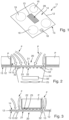
- Fig. 1 an oblique view onto a cooktop 11 according to the invention is shown.
- the cooktop 11 has a cooktop plate 12, which preferably is made from glass ceramic, having an upper side 14 and an underside 15.
- the cooktop 11 has a rectangular suction opening 13 in it, which suction opening 13 is a kind of cutout in the cooktop plate 12.
- the cooktop 11 has four induction heating coils 16, which form heating points to heat a pot placed onto the cooktop plate 12 above it.
- a user interface 18 is provided close to the front edge of the cooktop plate 12, a user interface 18 is provided.
- the user interface 18 is also connected to a cooktop control which is shown later.
- Such a cooktop control is basically known in the art and cannot only control any input and output on the user interface 18, but also control power supply to the induction heating coils 16. It may further control the weight detection device of the invention and any information regarding a weight detection which is output at the user interface 18.
- a weight detection device is provided underneath a cover 20 which is placed inside the suction opening 13 to cover it.
- the cover 20 is preferably designed as a grille with slits and ribs or the like. This provides for a closure of the suction opening 13 such that larger objects cannot fall into the suction opening 13. Cooking fumes, air and the like can, however, be sucked in as is known in the art.
- the cover 20 is placed inside the suction opening 13 in the cooktop plate 12.
- the cover 20 has an upper side 21 and an underside 22. Ribs 23 as mentioned before run along the longitudinal direction of the cover 20 as a grille. These ribs 23 protrude over the underside 22. This allows for the upper side 21 of the cover 20 to be flush with the upper side 14 of the cooktop plate 12 or very slightly beneath it.
- two pots P are placed upon the cooking points or the induction heating coils, respectively, for heating. Fumes F rising from the pots P or their content, respectively, such as for example boiling water, are sucked into the suction opening 13 as shown.
- the fumes F can go right through the grille-like cover 20 into an air duct 24 beneath it. This air duct 24 is shown only very schematically. It leads to a grease filter 50 and to a fan 25 below it, which are also shown only schematically.
- Fig. 2 shows a kind of cover state according to a first case of an arrangement.
- the pots P can even be moved somewhat above the cover 20 without any problem or causing damage. This allows for more comfort in using the cooktop 11.
- a weighing state is shown as a second case of use.
- the cover 20 can easily be taken off from the cooktop plate 12 and out of the suction opening 13, can be turned around by 180° and then be placed again into the suction opening 13. Again, the cover 20 is supported on the weighing sensors 32, but in this case with its upper side 21.
- the underside 22 with the protruding ribs 23 is now pointing upwards, and a pot P is placed upon the cover 20 or the ribs 23, respectively. This is done for weighing the pot P with its content.
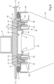
- FIG. 4 an exploded view onto the construction of a weight detection device 40 is shown, starting from the left.
- a support device 26 in the form of a rectangular frame is provided, preferably made of metal or of plastic.
- the support device 26 has horizontal receiving openings 28 which form chambers or the like. Close to each end of the receiving openings 28 and in opposite directions, longitudinal openings 30 are provided on the upper sides.
- Weighing sensors 32 can be placed into the receiving openings 28.
- the weighing sensors 32 in this case are in the form of beams as sensor carrier holders and are provided with strain gauges on their upper side and underside as is basically known in the art.
- the weighing sensors 32 are affixed to the support device 26 with several screws 41 from below, wherein this fixture is at the opposite end in the receiving opening 28 of the opening 30.
- the screws 41 provide a fixed position of one end of the weighing sensors 32, whereas the other end is located underneath the opening 30 and can be bent down by a weight placed upon it.
- the weighing sensor 32 consequently needs such measurement path to be able to move or bend somewhat downwards, which is but no problem.
- the region of the weighing sensors 32 underneath the openings 30 are the pressure regions mentioned above.
- the weight detection device 40 is then affixed to the underside 15 of the cooktop table 12 such that it is congruent with the suction opening 13.
- This fixture may be made by gluing.
- An upper side of the support device 26 can rest against the underside 15 of the cooktop plate 12.
- this upper side of the support device 26 is visible in the suction opening 13 from above such that the inner opening inside the support device 26 is somewhat smaller than the suction opening 13.
- the two openings 30 are also completely visible and freely accessible from above inside the suction opening 13.
- Support parts 43 are placed upon them.
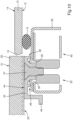
- the support parts 43 which can also be taken from Figs. 9 and 10 , are angled twice and in the form of profiles with an upper side 44 and angular sections pointing into the suction opening 13 and at each other. These angular sections form filter holders 46 and reach into the central opening of the support device 26.
- the support parts 43 are affixed to the weighing sensors 32 with two screws 47, which can also be seen in Figs. 9 and 10 .
- This allows for the support parts 43, onto which the cover 20 is placed, to be directly connected with and supported on the weighing sensors 32.
- any weight of the cover 20 and any objects on it are then transferred directly onto the weighing sensors 32.
- these will bend down slightly with a measuring path directly corresponding to the weight, and this measuring path can be measured by the strain gauges placed on it for an exact weight measurement.
- a grease filter 50 is inserted from above into the suction opening 13 such that it is mainly beneath the suction opening 13 in the air duct 24.
- the rim 51 of the grease filter 50 on the short lateral sides is directly placed upon the filter holder 46 of the support part 43, see Fig. 9 . This serves to be able to also measure a variable weight of the grease filter 50 with the weight detection device 40.
- the cover 20 can also be placed from above into the suction opening 13, where it is supported only on the two support parts 43 or their upper side 44, respectively. This serves to be able to divide any force Fp of a pot P placed upon the cover 20 or its upper side 21, respectively, according to Fig. 9 into two forces F 1 and F 2 onto the weighing sensors 32 in their receiving openings 28 of the support device 26.
- the length of the support parts 43 is only slightly shorter than the short lateral sides of the suction opening 13 such that the cover 20 is placed in stable and reliable manner on it.
- the position of the pot P on the cover 20 does not play any role for the weight measurement, as the force of the weight of the pot P, of course together with the one of the cover 20 and the grease filter 50, is always the sum of the two forces F 1 and F 2 at the weighing sensors 32. These forces F 1 and F 2 are acting upon the upper sides 44 of the support parts 43 such that these upper sides in this area form the pressure regions mentioned at the beginning.
- the pot P is positioned more to the left side resulting in the force F 1 to be larger than the force F 2 . This shows in the arrow of force F 1 to be longer than the arrow of force F 2 .
- Fig. 9 it can also be taken that the support device 26 is glued with glue G to the underside 15 of the cooktop plate 12 shortly outside of the suction opening 13.
- glue G also has a sealing function.
- the glue layer G could be significantly thinner than shown here.
- a watertight seal between the support parts 43 and the support device 26 cannot be provided because this seal due to its elastic characteristics would have a negative impact on the weighing precision. Basically, it does not pose a problem if liquid from cooking processes can run into the air duct 24, as it can be collected either by a separate collecting container or in the grease filter 50. It should, however, be avoided that such liquid can spill over the edge of the suction opening 13, drop down onto the upper side of the support device 26 and find its way inside the support device 26 where the weighing sensor 32 is placed, for example through the opening 30. To avoid that, in Fig. 10 a so-called labyrinth seal 48 is provided being effective between the support part 43 and the upper side of the support device 26 around the opening 30.
- Figs. 9 and 10 it can also easily be taken that the above-mentioned strain gauges could be placed on the upper side and on the underside of the weighing sensors 32 or their beam-like parts, respectively. Any electrical connection of the weighing sensors 32 to a cooktop control are not shown, but can easily be made.
- FIG. 11 shows an arrangement of a support device 26 with three weighing sensors 32a, 32b and 32c.
- a single weighing sensor 32a is provided at one short side of the support device 26.
- the other two weighing sensors 32b and 32c are provided on the longer lateral sides close to the opposing short lateral side. This allows for a support of the cover on three points, which provides a stable position.
- weighing sensors 32a to 32d are provided on the support device 26. They are each provided at the end of the longer lateral sides shortly before the short lateral sides. The provision of four weighing sensors provides for a maximum stable position and support of the cover, for example compared to the configuration of Fig. 11 .
- Fig. 13 shows two weighing sensors 32a and 32b. They are arranged at the longer lateral sides shortly before the short lateral sides.
- FIG. 14 Another embodiment of the invention similar to the one of Fig. 4 is shown in Fig. 14 .
- a support device 126 has receiving openings 128 at its short lateral sides, similar to the ones of Fig. 4 .
- four weighing sensors 132 are placed inside the receiving openings 128 close to the ends of the receiving openings 128.
- the weighing sensors 132 are shown in more detail in Fig. 15 and will be explained later.
- openings 130 are provided above the location of each weighing sensor 132.
- the support device 126 is then affixed to the underside 115 of the cooktop plate 112 having the suction opening 113.
- small and very simple support parts 143 are placed into the openings 130. They are directly supported on the weighing sensors 132.
- the support parts 143 have a rather wide head and a thin and long part pointing downwards.
- the cover 120 will be placed upon the four support parts 143 having a stable position. Any force by the weight of the cover 120 and any object placed thereon is transferred via the support parts 143 to the weighing sensors 132.
- a kind of labyrinth seal similar to Figs. 9 and 10 can be provided between the support parts 143 and the upper side of the support device 126 around the openings 130.
- the weighing sensor 132 has a sensor carrier holder 134, which preferably is a plastic part and serves to place the sensor carrier 136 on it.
- the sensor carrier 136 can be snapped onto the sensor carrier holder 134.
- the sensor carrier 136 should be made of metal or steel, respectively. This provides for better flexibility and, more important, a rather linear behavior when a force by the cover 20 is exerted on it.
- the sensor carrier 136 is in the form of a spiral and has an inner free end 137. This free end 137 is freely movable downwards as a movement path mentioned before.
- the support parts 143 of Fig. 14 are resting against these free ends 137 such that the free ends 137 form the pressure regions mentioned at the beginning.
- the free end 137 With increasing weight force from above, the free end 137 will be bent downwards, and a strain gauge 138 fixed to the upper side of the sensor carrier 136 rather close to the free end 137 will be strained accordingly. As it can preferably be a variable resistor, this is in known manner leading to a change in electrical resistance, which again can be read out as a specific force.
- the sensor carrier holder 134 is also provided below the free end 137 so as to serve as a stop for a maximum bending, for example corresponding to 5 kg or max. 10 kg put onto the cover 120.
- FIG. 16 an embodiment of the invention with partial covers 220a and 220b is shown.
- the partial covers 220a and 220b are placed inside a suction opening 213 in the cooktop plate 212. They have an axis of rotation not shown here, but running straight into the drawing plane ad through the m partial covers 220a and 220b.
- the left partial cover 220a can be rotated clockwise and the right partial cover 220b can be rotated anti-clockwise from the cover state shown on the left side into a weighing state shown on the right side.
- the edge faces of the two partial covers 220a and 220b facing each other on the left side are then resting directly upon the weighing sensors 232a and 232b.
- a pot P can be placed on the opposite edge faces pointing upwards for a weighing process.
- an additional cover can be placed upon the edge faces of the partial covers to have a somewhat uninterrupted and more comfortable plane for putting any arbitrary object to be weighed upon.
- the advantage of this embodiment obviously is that in the cover state the weighing sensors 232a and 232b are not exposed to any weight or force by an external weight. Only if by rotating the partial covers 220a and 220b the weighing function is explicitly wanted for they are somehow activated.
- the mechanical precision must be very high for the lower edge faces of the partial covers 220a and 220b to rest upon the weighing sensors 232a and 232b without exerting significant force, because such a force might be misinterpreted as a weight placed upon the partial covers. This can be reached for example by an axis of rotation which has some degree of vertical freedom or movability, respectively.
- a user must make a taring operation after having rotated the partial covers 220a and 220b into the weighing position and before any weight to be measured is placed thereupon.
- FIG. 17 An alternative embodiment of such a two-part cover is shown in Fig. 17 .
- the two partial covers 320a and 320b are closed and roughly in the plane of the cooktop plate 312 inside the suction opening 313.
- the left partial cover 320a and the right partial cover 320b are already connected and coupled to weighing sensors 332a and 332b.
- An axis of rotation again is not shown, but can be the same as in Fig. 17 and allows for the partial covers 320 to be rotated similar to Fig. 16 , but together with the weighing sensors 332. This can be taken from Fig. 17 on the right side.
- the weighing sensors 332 can be designed in such a way that they can measure the weight of the partial covers and in particular of a pot P placed upon their edge faces pointing upwards in this weighing position. This could, alternatively, also be made if an axis of rotation of the partial covers 320 is directly supported on weighing sensors.
- Fig. 17 allows for the partial covers 320 to always be in connection and, consequently, in known and defined manner with the weighing sensors 332, which allows for a more precise weight measurement.
- FIG. 18 Another embodiment of the invention is shown in Fig. 18 where two partial cooktop plates 412a and 412b with induction heating coils 416 of a cooktop 411 are provided having a distance to each other of about 10 cm to 15 cm. Between them the cooktop 411 has a suction opening 413 covered by a cover 420.
- This cover 420 is, according to the embodiments described before, placed upon a support device of a weight detection device underneath the suction opening 413.
- the cooktop 411 with its partial cooktop plates 412a and 412b as well as the weight detection device, the suction opening 413 and the cover 420 can be designed as one appliance with one housing which is mounted in a respective opening in a working table in a kitchen.
- Such an appliance will also comprise the air duct, the fan and the other functional components.
- the cooktop 411 has separate and independent partial cooktop plates 412a and 412b, potentially further such partial cooktop plates placed beside them, which can be mounted individually and preferably with different heating means.
- the suction opening 413 with the cover 412 can also be a separate module mounted at the same working table as the partial cooktop plates.
- This module will then also comprise the air duct, the grease filter and the fan and the like. It can have its own independent control and user interface for the suction function as well as for any weighing function of a weight detection device incorporated therein. As an alternative, it can be connected to a cooktop control as described before.
- FIG. 19 Another embodiment of the invention is shown in Fig. 19 , wherein a separate weighing system 539 with a weight detection device 540 is provided on a cooktop 511.
- the cooktop 511 has a cooktop plate 512 with a suction opening 513 and all the functionalities needed for the suction function as described before.
- the cooktop 511 is mounted in a working table 510.
- the weighing system 539 is placed in a suction opening 513 together with its weight detection device 540, whereas any supporting part inside and underneath the suction opening 513 does not contain any weighing sensors.
- the weighing system 539 comprises a cover which can also be formed as a grille described before and have its own weight detection device 540 comprising a support device onto which such a cover is placed.
- the weighing system 540 also comprises wireless communication means as is basically known in the art to exchange data with the cooktop control 519. This allows for the weighing system 539 to be taken out of the suction opening 513 and be placed somewhere onto the working table 510. A wireless connection to a cooktop control 519 can then be established, which is also possible when the weighing system 539 is placed inside the suction opening 513.
- the weighing system 539 also has its own energy source, which can preferably be an accumulator that can be charged wirelessly when the weighing system 539 is placed inside or above the suction opening 513.
- the suction function of the cooktop 511 can still be used when the weighing system 539 itself is in the remote function state as shown in the lower part of Fig. 19 . Any information about a weight result can either be displayed on a separate display or user interface of the weighing system 539 or on a user interface of the cooktop 511 itself according to Fig. 1 .
Landscapes
- Engineering & Computer Science (AREA)
- Chemical & Material Sciences (AREA)
- Combustion & Propulsion (AREA)
- Mechanical Engineering (AREA)
- General Engineering & Computer Science (AREA)
- Electric Stoves And Ranges (AREA)
Priority Applications (1)
| Application Number | Priority Date | Filing Date | Title |
|---|---|---|---|
| EP22204066.9A EP4361503A1 (fr) | 2022-10-27 | 2022-10-27 | Table de cuisson |
Applications Claiming Priority (1)
| Application Number | Priority Date | Filing Date | Title |
|---|---|---|---|
| EP22204066.9A EP4361503A1 (fr) | 2022-10-27 | 2022-10-27 | Table de cuisson |
Publications (1)
| Publication Number | Publication Date |
|---|---|
| EP4361503A1 true EP4361503A1 (fr) | 2024-05-01 |
Family
ID=84043752
Family Applications (1)
| Application Number | Title | Priority Date | Filing Date |
|---|---|---|---|
| EP22204066.9A Withdrawn EP4361503A1 (fr) | 2022-10-27 | 2022-10-27 | Table de cuisson |
Country Status (1)
| Country | Link |
|---|---|
| EP (1) | EP4361503A1 (fr) |
Cited By (1)
| Publication number | Priority date | Publication date | Assignee | Title |
|---|---|---|---|---|
| EP4722598A1 (fr) * | 2024-10-01 | 2026-04-08 | V-Zug AG | Table de cuisson avec hotte aspirante et balance |
Citations (2)
| Publication number | Priority date | Publication date | Assignee | Title |
|---|---|---|---|---|
| DE102012216935A1 (de) | 2012-09-20 | 2014-03-20 | E.G.O. Elektro-Gerätebau GmbH | Kochfeld und Anordnung und Verfahren zum Betrieb eines Kochfelds |
| WO2019138312A1 (fr) | 2018-01-12 | 2019-07-18 | Elica S.P.A. | Plaque de cuisson à unité d'extraction et balance intégrées |
-
2022
- 2022-10-27 EP EP22204066.9A patent/EP4361503A1/fr not_active Withdrawn
Patent Citations (3)
| Publication number | Priority date | Publication date | Assignee | Title |
|---|---|---|---|---|
| DE102012216935A1 (de) | 2012-09-20 | 2014-03-20 | E.G.O. Elektro-Gerätebau GmbH | Kochfeld und Anordnung und Verfahren zum Betrieb eines Kochfelds |
| WO2019138312A1 (fr) | 2018-01-12 | 2019-07-18 | Elica S.P.A. | Plaque de cuisson à unité d'extraction et balance intégrées |
| US20210063234A1 (en) * | 2018-01-12 | 2021-03-04 | Elica S.P.A. | Cooktops with integrated extraction hoods and scales |
Cited By (1)
| Publication number | Priority date | Publication date | Assignee | Title |
|---|---|---|---|---|
| EP4722598A1 (fr) * | 2024-10-01 | 2026-04-08 | V-Zug AG | Table de cuisson avec hotte aspirante et balance |
Similar Documents
| Publication | Publication Date | Title |
|---|---|---|
| ES2773000T3 (es) | Aparato para cocinar alimentos | |
| EP4361503A1 (fr) | Table de cuisson | |
| EP2999301B1 (fr) | Plaque de cuisson à induction avec détection d'ébullition et commande de l'énergie par induction, procédé pour chauffer des aliments avec une plaque de cuisson à induction et programme informatique | |
| JP5479955B2 (ja) | 天秤 | |
| EP3737891B1 (fr) | Plaque de cuisson avec unité d'aspiration et balance intégré | |
| US7307246B2 (en) | System and method of detecting temperature of a cooking utensil over a radiant cooktop | |
| ES2340133B1 (es) | Dispositivo de coccion provisto de unos medios sensores de peso. | |
| ES2976637T3 (es) | Un medio o módulo sensor para determinar un desplazamiento, en particular un desplazamiento elástico, de un inserto en relación con un panel | |
| JP3036633U (ja) | 乾燥装置 | |
| US20230400190A1 (en) | Cooktop and resilient element support | |
| CN206062928U (zh) | 一种内锅和烹饪器具 | |
| CN216960241U (zh) | 线圈盘、锅盖组件及烹饪器具 | |
| CN107684348B (zh) | 一种内锅和烹饪器具 | |
| JP2005009771A (ja) | 加熱調理器とそれに用いた静電容量式重量センサ | |
| CN206080212U (zh) | 一种内锅和烹饪器具 | |
| CN206959028U (zh) | 电磁炉 | |
| CN222187043U (zh) | 一种燃气灶锅架、用于燃气灶的检测组件和燃气灶 | |
| CN208902239U (zh) | 一种蒸汽发热体的水蒸气收集称量装置 | |
| CN204862573U (zh) | 一种电热锅 | |
| CN206137933U (zh) | 一种内锅和烹饪器具 | |
| KR20050076579A (ko) | 전기 가열 조리기 | |
| US20240240799A1 (en) | Cooktop appliance having a removable griddle assembly and temperature probe therefor | |
| US12610432B2 (en) | Systems for touch foil alignment in appliances | |
| CN217302901U (zh) | 检测模组及具有其的烹饪器具 | |
| CN115003961B (zh) | 带有热保护器的燃气灶具 |
Legal Events
| Date | Code | Title | Description |
|---|---|---|---|
| PUAI | Public reference made under article 153(3) epc to a published international application that has entered the european phase |
Free format text: ORIGINAL CODE: 0009012 |
|
| STAA | Information on the status of an ep patent application or granted ep patent |
Free format text: STATUS: THE APPLICATION HAS BEEN PUBLISHED |
|
| AK | Designated contracting states |
Kind code of ref document: A1 Designated state(s): AL AT BE BG CH CY CZ DE DK EE ES FI FR GB GR HR HU IE IS IT LI LT LU LV MC ME MK MT NL NO PL PT RO RS SE SI SK SM TR |
|
| STAA | Information on the status of an ep patent application or granted ep patent |
Free format text: STATUS: THE APPLICATION IS DEEMED TO BE WITHDRAWN |
|
| 18D | Application deemed to be withdrawn |
Effective date: 20241105 |