EP4362155A1 - Batterie - Google Patents
Batterie Download PDFInfo
- Publication number
- EP4362155A1 EP4362155A1 EP22828061.6A EP22828061A EP4362155A1 EP 4362155 A1 EP4362155 A1 EP 4362155A1 EP 22828061 A EP22828061 A EP 22828061A EP 4362155 A1 EP4362155 A1 EP 4362155A1
- Authority
- EP
- European Patent Office
- Prior art keywords
- counter
- electrode
- active material
- electrode active
- material layers
- Prior art date
- Legal status (The legal status is an assumption and is not a legal conclusion. Google has not performed a legal analysis and makes no representation as to the accuracy of the status listed.)
- Pending
Links
Images


Classifications
-
- H—ELECTRICITY
- H01—ELECTRIC ELEMENTS
- H01M—PROCESSES OR MEANS, e.g. BATTERIES, FOR THE DIRECT CONVERSION OF CHEMICAL ENERGY INTO ELECTRICAL ENERGY
- H01M10/00—Secondary cells; Manufacture thereof
- H01M10/05—Accumulators with non-aqueous electrolyte
- H01M10/058—Construction or manufacture
- H01M10/0585—Construction or manufacture of accumulators having only flat construction elements, i.e. flat positive electrodes, flat negative electrodes and flat separators
-
- H—ELECTRICITY
- H01—ELECTRIC ELEMENTS
- H01M—PROCESSES OR MEANS, e.g. BATTERIES, FOR THE DIRECT CONVERSION OF CHEMICAL ENERGY INTO ELECTRICAL ENERGY
- H01M10/00—Secondary cells; Manufacture thereof
- H01M10/05—Accumulators with non-aqueous electrolyte
- H01M10/052—Li-accumulators
-
- H—ELECTRICITY
- H01—ELECTRIC ELEMENTS
- H01M—PROCESSES OR MEANS, e.g. BATTERIES, FOR THE DIRECT CONVERSION OF CHEMICAL ENERGY INTO ELECTRICAL ENERGY
- H01M10/00—Secondary cells; Manufacture thereof
- H01M10/05—Accumulators with non-aqueous electrolyte
- H01M10/052—Li-accumulators
- H01M10/0525—Rocking-chair batteries, i.e. batteries with lithium insertion or intercalation in both electrodes; Lithium-ion batteries
-
- H—ELECTRICITY
- H01—ELECTRIC ELEMENTS
- H01M—PROCESSES OR MEANS, e.g. BATTERIES, FOR THE DIRECT CONVERSION OF CHEMICAL ENERGY INTO ELECTRICAL ENERGY
- H01M10/00—Secondary cells; Manufacture thereof
- H01M10/05—Accumulators with non-aqueous electrolyte
- H01M10/056—Accumulators with non-aqueous electrolyte characterised by the materials used as electrolytes, e.g. mixed inorganic/organic electrolytes
- H01M10/0561—Accumulators with non-aqueous electrolyte characterised by the materials used as electrolytes, e.g. mixed inorganic/organic electrolytes the electrolyte being constituted of inorganic materials only
- H01M10/0562—Solid materials
-
- H—ELECTRICITY
- H01—ELECTRIC ELEMENTS
- H01M—PROCESSES OR MEANS, e.g. BATTERIES, FOR THE DIRECT CONVERSION OF CHEMICAL ENERGY INTO ELECTRICAL ENERGY
- H01M4/00—Electrodes
- H01M4/02—Electrodes composed of, or comprising, active material
- H01M4/64—Carriers or collectors
-
- H—ELECTRICITY
- H01—ELECTRIC ELEMENTS
- H01M—PROCESSES OR MEANS, e.g. BATTERIES, FOR THE DIRECT CONVERSION OF CHEMICAL ENERGY INTO ELECTRICAL ENERGY
- H01M50/00—Constructional details or processes of manufacture of the non-active parts of electrochemical cells other than fuel cells, e.g. hybrid cells
- H01M50/50—Current conducting connections for cells or batteries
- H01M50/572—Means for preventing undesired use or discharge
- H01M50/584—Means for preventing undesired use or discharge for preventing incorrect connections inside or outside the batteries
- H01M50/586—Means for preventing undesired use or discharge for preventing incorrect connections inside or outside the batteries inside the batteries, e.g. incorrect connections of electrodes
-
- H—ELECTRICITY
- H01—ELECTRIC ELEMENTS
- H01M—PROCESSES OR MEANS, e.g. BATTERIES, FOR THE DIRECT CONVERSION OF CHEMICAL ENERGY INTO ELECTRICAL ENERGY
- H01M50/00—Constructional details or processes of manufacture of the non-active parts of electrochemical cells other than fuel cells, e.g. hybrid cells
- H01M50/50—Current conducting connections for cells or batteries
- H01M50/572—Means for preventing undesired use or discharge
- H01M50/584—Means for preventing undesired use or discharge for preventing incorrect connections inside or outside the batteries
- H01M50/59—Means for preventing undesired use or discharge for preventing incorrect connections inside or outside the batteries characterised by the protection means
- H01M50/591—Covers
-
- H—ELECTRICITY
- H01—ELECTRIC ELEMENTS
- H01M—PROCESSES OR MEANS, e.g. BATTERIES, FOR THE DIRECT CONVERSION OF CHEMICAL ENERGY INTO ELECTRICAL ENERGY
- H01M2300/00—Electrolytes
- H01M2300/0017—Non-aqueous electrolytes
- H01M2300/0065—Solid electrolytes
-
- Y—GENERAL TAGGING OF NEW TECHNOLOGICAL DEVELOPMENTS; GENERAL TAGGING OF CROSS-SECTIONAL TECHNOLOGIES SPANNING OVER SEVERAL SECTIONS OF THE IPC; TECHNICAL SUBJECTS COVERED BY FORMER USPC CROSS-REFERENCE ART COLLECTIONS [XRACs] AND DIGESTS
- Y02—TECHNOLOGIES OR APPLICATIONS FOR MITIGATION OR ADAPTATION AGAINST CLIMATE CHANGE
- Y02E—REDUCTION OF GREENHOUSE GAS [GHG] EMISSIONS, RELATED TO ENERGY GENERATION, TRANSMISSION OR DISTRIBUTION
- Y02E60/00—Enabling technologies; Technologies with a potential or indirect contribution to GHG emissions mitigation
- Y02E60/10—Energy storage using batteries
-
- Y—GENERAL TAGGING OF NEW TECHNOLOGICAL DEVELOPMENTS; GENERAL TAGGING OF CROSS-SECTIONAL TECHNOLOGIES SPANNING OVER SEVERAL SECTIONS OF THE IPC; TECHNICAL SUBJECTS COVERED BY FORMER USPC CROSS-REFERENCE ART COLLECTIONS [XRACs] AND DIGESTS
- Y02—TECHNOLOGIES OR APPLICATIONS FOR MITIGATION OR ADAPTATION AGAINST CLIMATE CHANGE
- Y02P—CLIMATE CHANGE MITIGATION TECHNOLOGIES IN THE PRODUCTION OR PROCESSING OF GOODS
- Y02P70/00—Climate change mitigation technologies in the production process for final industrial or consumer products
- Y02P70/50—Manufacturing or production processes characterised by the final manufactured product
Definitions
- the present disclosure relates to a battery.
- PTL 1 and PTL 2 each disclose a battery including an insulating member.
- the conventional technology is required to improve the reliability of a battery.
- the present disclosure has as an object to provide a highly reliable battery.
- a battery includes an electrode collector, two electrode active material layers disposed on both principal surfaces of the electrode collector, two solid electrolyte layers each disposed on a side of a corresponding one of the two electrode active material layers that is disposed on the opposite side of the electrode collector, two counter-electrode active material layers each disposed on a side of a corresponding one of the two solid electrolyte layers that is disposed on the opposite side of the corresponding one of the two electrode active material layers, two counter-electrode collectors each disposed on a side of a corresponding one of the two counter-electrode active material layers that is disposed on the opposite side of the corresponding one of the two solid electrolyte layers, and a first insulating layer that covers side surfaces of the two counter-electrode collectors, the two counter-electrode active material layers, the two solid electrolyte layers, and the two electrode active material layers.
- a first region not covered with any of the two electrode active material layers is provided at ends of both principal surfaces of the electrode collector.
- a second region not covered with any of the two counter-electrode collectors is provided at an end of a principal surface of each of the two counter-electrode active material layers that faces toward a corresponding one of the counter-electrode collectors.
- the first insulating layer covers the second region.
- the electrode collector projects from an outer surface of the first insulating layer.
- the present disclosure makes it possible to provide a highly reliable battery.
- a battery such as an all-solid battery, including solid electrolyte layers each containing a solid electrolyte
- the inventor studied to form terminals at ends of the battery. Specifically, in a case where electrode active material layers are formed on both surfaces of an identical electrode collector, the inventor attempted to form terminals in regions provided at ends of the electrode collector and not covered with the electrode active material layers.
- an end face short circuit due to contact with the electrode collector tends to occur when counter-electrode collectors project further than counter-electrode active material layers.
- a misalignment between the cells thus laminated undesirably increases the likelihood of an end face short circuit.
- ends of the active material layers are exposed, the falling off of active materials undesirably makes it easy for a short circuit to occur. Such problems cause a deterioration in reliability of the battery.
- the present disclosure provides a highly reliable battery.
- a battery includes an electrode collector, two electrode active material layers disposed on both principal surfaces of the electrode collector, two solid electrolyte layers each disposed on a side of a corresponding one of the two electrode active material layers that is disposed on the opposite side of the electrode collector, two counter-electrode active material layers each disposed on a side of a corresponding one of the two solid electrolyte layers that is disposed on the opposite side of the corresponding one of the two electrode active material layers, two counter-electrode collectors each disposed on a side of a corresponding one of the two counter-electrode active material layers that is disposed on the opposite side of the corresponding one of the two solid electrolyte layers, and a first insulating layer that covers side surfaces of the two counter-electrode collectors, the two counter-electrode active material layers, the two solid electrolyte layers, and the two electrode active material layers.
- a first region not covered with any of the two electrode active material layers is provided at ends of both principal surfaces of the electrode collector.
- a second region not covered with any of the two counter-electrode collectors is provided at an end of a principal surface of each of the two counter-electrode active material layers that faces toward a corresponding one of the counter-electrode collectors.
- the first insulating layer covers the second region.
- the electrode collector projects from an outer surface of the first insulating layer.
- the formation of the first insulating layer reduces exposure of the electrode active material layers and the counter-electrode active material layers. This reduces the occurrence of damage, a short circuit, or other failures due to contact of the electrode active material layers and the counter-electrode active material layers with other members. This makes it possible to enhance the reliability of the battery.
- a length of the second region on a straight line connecting one point on an outer edge of the battery with a center of the battery and intersecting the second region in planar view may be greater than or equal to 100 ⁇ m.
- a length of the first region on a straight line connecting one point on an outer edge of the battery with a center of the battery and intersecting the first region in planar view may be greater than or equal to 1 mm.
- a thickness of a portion of the first insulating layer that covers the second region may be greater than a thickness of each of the counter-electrode collectors.
- each of the electrode active material layers may contain a negative-electrode active material
- each of the counter-electrode active material layers may contain a positive-electrode active material
- the electrode collector and each of the electrode active material layers may be a negative-electrode collector and a negative-electrode active material layer, respectively
- each of the counter-electrode collectors and each of the counter-electrode active material layers may be a positive-electrode collector and a positive-electrode active material layer, respectively.
- the first insulating layer may contain resin.
- the first insulating layer may contain a metallic oxide.
- the first insulating layer hard. Therefore, even in a case where the first insulating layer is thinly formed at the time of manufacture of the battery, the first insulating layer thus formed hardly deforms and is uniform in thickness.
- the solid electrolyte layer may contain a solid electrolyte having lithium ion conductivity.
- a planimetric shape of the battery may be a rectangle, and the first insulating layer may be provided at least on one side of the battery in planar view.
- a side surface of a side on which the first insulating layer is not provided may be a cut surface.
- the side surfaces of the battery are cut surfaces, a side surface of the electrode layer, side surfaces of the counter-electrode layers, and side surfaces of the solid electrolyte layers can be easily made flush with one another.
- a shape of the cut surface may be a rectangle or a trapezoid.
- the electrode collector, the two electrode active material layers, the two solid electrolyte layers, the two counter-electrode active material layers, and the two counter-electrode collectors may constitute a unit cell, and a plurality of the unit cells may be laminated.
- the battery may further include a second insulating layer that covers ones of the side surfaces of the two counter-electrode collectors, the two counter-electrode active material layers, the two solid electrolyte layers, and the two electrode active material layers that are not covered with the first insulating layer, and at least one of a plurality of the counter-electrode collectors may project from an outer surface of the second insulating layer.
- drawings are schematic views, and are not necessarily strict illustrations. Accordingly, for example, the drawings are not necessarily to scale. Further, in the drawings, substantially the same components are given the same reference signs, and a repeated description may be omitted or simplified.
- the x axis, the y axis, and the z axis represent the three axes of a three-dimensional orthogonal coordinate system.
- the planimetric shape of a power-generating element of a battery is a rectangle
- the x axis and the y axis extend in directions parallel with a first side of the rectangle and a second direction orthogonal to the first side, respectively.
- the z axis extends in a direction of laminating of a plurality of unit cells included in the power-generating element.
- the term "direction of laminating” as used herein corresponds to a direction normal to principal surfaces of a collector and an active material layer.
- the term “planar view” used herein means a case where the battery is seen from an angle perpendicular to the principal surfaces, unless otherwise noted.
- the terms “above” and “below” used herein do not refer to an upward direction (upward in a vertical direction) and a downward direction (downward in a vertical direction) in absolute space recognition, but are used as terms that are defined by a relative positional relationship on the basis of an order of laminating in a laminate configuration. Further, the terms “above” and “below” are applied not only in a case where two constituent elements are placed at a spacing from each other with another constituent element present between the two constituent elements, but also in a case where two constituent elements touch each other by being placed in close contact with each other. In the following description, the negative side of the z axis is referred to as “below” or “lower”, and the positive side of the z axis is referred to as “above” or "upper”.
- the term "project” as used herein means projecting further outward than the center of a unit cell in a view of a cross-section orthogonal to a principal surface of the unit cell, unless otherwise noted.
- the clause "an element A projects further than an element B” means that a distal end of the element A projects further than a distal end of the element B in a direction of projection, i.e., that the distal end of the element A is further away from the center of the unit cell than the distal end of the element B.
- the "direction of projection” is deemed to be a direction parallel with the principal surface of the unit cell.
- the term “projecting portion of the element A” means a portion of the element A that projects further than the tip of the element B in the direction of projection. Examples of elements include electrode layers, active material layers, solid electrolyte layers, and collectors.
- ordinal numbers such as “first” and “second” as used herein do not mean the number or order of constituent elements but are used for the purpose of avoiding confusion between constituent elements of the same type and distinguishing between them, unless otherwise noted.
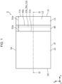
- Fig. 1 is a schematic top view showing an example of a battery 1 according to the present embodiment.
- the planimetric shapes of constituent elements of the battery 1 are indicated by solid lines and dashed lines.
- Fig. 2 is a schematic cross-sectional view of the battery 1 according to the present embodiment as taken along line II-II in Fig. 1 .
- the battery 1 includes an electrode layer 10, counter-electrode layers 20 placed opposite the electrode layer 10, and solid electrolyte layers 30 each located between the electrode layer 10 and a corresponding one of the counter-electrode layers 20.
- the battery 1 includes two counter-electrode layers 20 and two solid electrolyte layers 30. A first one of the counter-electrode layers 20 and a first one of the solid electrolyte layers 30 are disposed beside a first principal surface of the electrode layer 10, and a second one of the counter-electrode layers 20 and a second one of the solid electrolyte layers 30 are disposed beside a second principal surface of the electrode layer 10.
- the electrode layer 10, the two counter-electrode layers 20, and the two solid electrolyte layers 30 constitute a unit cell 2.
- the electrode layer 10 includes an electrode collector 11 and electrode active material layers 12 each located between the electrode collector 11 and a corresponding one of the solid electrolyte layers 30.
- the electrode layer 10 includes two electrode active material layers 12.
- the two electrode active material layers 12 are disposed on both principal surfaces of the electrode collector 11. At an end of a principal surface 11a of the electrode collector 11, there is provided a region 51a not covered with an upper one of the electrode active material layers 12. At an end of a principal surface 1 1b of the electrode collector 11, there is provided a region 51b not covered with a lower one of the electrode active material layers 12.
- the regions 51a and 51b are each an example of a first region not covered with any of the two electrode active material layers 12.
- the counter-electrode layers 20 include counter-electrode collectors 21 and counter-electrode active material layers 22 each located between a corresponding one of the counter-electrode collectors 21 and a corresponding one of the solid electrolyte layers 30.
- a region 52a not covered with an upper one of the counter-electrode collectors 21.
- a region 52b not covered with a lower one of the counter-electrode collectors 21.
- the regions 52a and 52b are each an example of a second region not covered with any of the two counter-electrode collectors 21.
- the battery 1 further includes an insulating layer 40 that covers side surfaces of the two electrode active material layers 12, the two solid electrolyte layers 30, the two counter-electrode active material layers 22, and the two counter-electrode collectors 21.
- the insulating layer 40 is an example of a first insulating layer. Specifically, as shown in Fig. 2 , the insulating layer 40 covers side surfaces 21c of the two counter-electrode collectors 21, side surfaces 22c of the two counter-electrode active material layers 22, side surfaces 30c of the two solid electrolyte layers 30, and side surfaces 12c of the two electrode active material layers 12. For example, the side surfaces 21c, 22c, 30c, and 12c are completely covered with the insulating layer 40 and are not exposed.
- the side surfaces 21c, 22c, 30c, and 12c are for example flat surfaces.
- the side surfaces 22c, 30c, and 12c are for example flush with one another, i.e., form a stepless identical flat surface.
- the electrode collector 11 has both a region covered with the insulating layer 40 and a region not covered with the insulating layer 40. In other words, the electrode collector 11 projects from an outer surface 40c of the insulating layer 40. That is, the electrode collector 11 includes a projecting portion 13 that projects outward from the outer surface 40c. In the region of the electrode collector 11 not covered with the insulating layer 40, it is easy to form an electrode terminal through which to take a current out of the electrode layer 10.
- planimetric shape of the battery 1 is a rectangle as shown in Fig. 1 , this is not intended to impose any limitation.
- the planimetric shape of the battery 1 may be a polygon such as a regular square, a hexagon, or an octagon or may be a circle or an ellipse.
- the battery 1 has side surfaces 1c and 1d that face opposed to each other and side surfaces 1e and 1f that face opposed to each other.
- the side surfaces 1c and 1d constitute short sides of the rectangular battery 1 in planar view.
- the side surfaces 1e and 1f constitute long sides of the rectangular battery 1 in planar view.
- the side surface 1c of the battery 1 is constituted by a side surface 11c of the electrode collector 11 and the outer surface 40c of the insulating layer 40.
- the electrode collector 11 is structured to have the projecting portion 13, which projects from the outer surface 40c of the insulating layer 40, at the side of the side surface 1c, this projecting portion 13 may be at the side of the side surface 1d or may be at the side of the side surface 1e or at the side of the side surface 1f.
- the battery 1 is for example an all-solid battery. Further, the side surfaces 1d, 1e, and 1f of the battery 1, which do not have the projecting portion 13 of the electrode collector 11, are flat surfaces. On each of these flat surfaces, a side surface of the electrode layer 10, side surfaces of the counter-electrode layers 20, and side surfaces of the solid electrolyte layers 30 are flush with one another. That is, they are in a stepless state and located on an identical flat surface. As a result of this, a side surface of the battery 1 that does not have the projecting portion 13 of the electrode collector 11 has no step between a side surface of one layer and a side surface of another layer and is free of irregularities.
- the side surfaces 1d, 1e, and 1f of the battery 1, which do not have the projecting portion 13 of the electrode collector 11, are for example cut surfaces.
- the side surfaces 1d, 1e, and 1f are surfaces formed by being cut with the cutting edge of a cutter or other tools for cutting.
- the side surfaces 1d, 1e, and 1f have, for example, traces of cutting such as fine grooves. Since the side surfaces are cut surfaces, a side surface of the electrode layer 10, side surfaces of the counter-electrode layers 20, and side surfaces of the solid electrolyte layers 30 can be easily made flush with one another. It should be noted that the traces of cutting may be smoothed by polishing or other processes.
- the planimetric shapes of the cut surfaces are not limited; however, in the case of the battery 1, the planimetric shapes of the cut surfaces are rectangles.
- the cut surfaces are for example parallel to a direction of laminating (z-axis direction) of the battery 1.
- the electrode collector 11 is in contact with the electrode active material layers 12 on both principal surfaces 11a and 11b.
- the regions 51a and 51b, which are not covered with the electrode active material layers 12, are provided at ends of at least one side of the electrode collector 11 in planar view.
- the region 51a has both a region covered with the insulating layer 40 and a region not covered with the insulating layer 40.
- the region not covered with the insulating layer 40 in planar view is equivalent to the projecting portion 13.
- the region 51a at the side of the upper surface has a similar configuration.
- the length of the region 51a is for example greater than or equal to 1 mm. Further, for example, the length of the region 51a is shorter than or equal to 20 mm. This makes it possible to prevent a terminal portion to overgrow in size and reduce the size of a portion that does not function as a battery, making it possible to improve the volume energy density of the battery 1.
- the length of the region 51a is a length on a straight line connecting a point on an outer edge of the battery 1 with the center of the battery 1 and intersecting the region 51a in planar view.
- the point on the outer edge is a point on the side surface 11c of the electrode collector 11 in planar view.
- the center of the battery 1 is the geometric center of the battery 1 in planar view.
- the center of the battery 1 is a point of intersection of diagonal lines in planar view.
- the straight line connecting the point on the outer edge of the battery 1 with the center of the battery 1 and intersecting the region 51a is for example line II-II shown in Fig. 1 . That is, the length of the region 51a is a length along an x-axis direction.
- the region 51a is a rectangular region elongated in a y-axis direction, this is not intended to impose any limitation.
- the length of the region 51a is equal to the length of the region 51b, this is not intended to impose any limitation.
- the length of the region 51a and the length of the region 51b may be different from each other.
- the thickness of the electrode collector 11 is for example greater than or equal to 5 ⁇ m and smaller than or equal to 100 ⁇ m but is not limited to this range.
- a publicly-known material may be used.
- a foil-like body, a plate-like body, a net-like body, or other bodies composed of, for example, copper, aluminum, nickel, iron, stainless steel, platinum, gold, an alloy of two or more types thereof, or other substances are used.
- the upper counter-electrode collector 21 is in contact with the principal surface 22a of the counter-electrode active material layer 22. At an end of at least one side of the counter-electrode collector 21, the region 52a, where the principal surface 22a of the counter-electrode active material layer 22 is not covered, is provided. That is, the counter-electrode collector 21 has a side surface receding from the counter-electrode active material layer 22. In other words, the side surface 21c of the counter-electrode collector 21 is closer to the center of the battery 1 than the side surface 22c of the counter-electrode active material layer 22.
- the length of the region 52a is for example greater than or equal to 100 ⁇ m. Further, for example, the length of the region 52a is for example shorter than or equal to 2 mm. This makes it possible, while preventing the area of the counter-electrode collector 21 from becoming too small, sufficiently secure a portion that functions as a battery, making it possible to improve the volume energy density of the battery 1.
- the length of the region 52a is a length on a straight line connecting a point on the outer edge of the battery 1 with the center of the battery 1 and intersecting the region 52a in planar view.
- the point on the outer edge, the center, and the straight line intersecting the region 52a are similar to those in the case of the region 51a. That is, the length of the region 52a is for example a length along line II-II shown in Fig. 1 and a length along the x-axis direction.
- the region 52a is a rectangular region elongated in the y-axis direction, this is not intended to impose any limitation.
- the length of the region 52a is equal to the length of the region 52b, this is not intended to impose any limitation.
- the length of the region 52a and the length of the region 52b may be different from each other.
- the receding side surface 21c of the counter-electrode collector 21 is in contact with a portion of the insulating layer 40 that covers the region 52a.
- an upper surface of the upper counter-electrode collector 21 and an upper surface of the insulating layer 40 are flush with each other.
- a lower surface of the lower counter-electrode collector 21 and a lower surface of the insulating layer 40 are flush with each other. This makes it possible to easily laminate the unit cell 2 to form a laminated battery. A specific example of the laminated battery will be described later in Embodiment 2.
- the thickness of the counter-electrode collector 21 is for example greater than or equal to 5 ⁇ m and smaller than or equal to 100 ⁇ m but is not limited to this range.
- a publicly-known material may be used.
- a foil-like body, a plate-like body, a net-like body, or other bodies composed of, for example, copper, aluminum, nickel, iron, stainless steel, platinum, gold, an alloy of two or more types thereof, or other substances are used.
- the electrode active material layers 12 are disposed on both principal surfaces 11a and 1 1b of the electrode collector 11. Further, a surface of each of the electrode active material layers 12 that is disposed on the opposite side of the electrode collector 11 is in contact with the corresponding one of the solid electrolyte layers 30. Each of the electrode active material layers 12 and a corresponding one of the counter-electrode active material layers 22 face each other across the corresponding one of the solid electrolyte layers 30. The side surfaces 12c of the electrode active material layers 12 are in contact with the insulating layer 40. Further, the electrode active material layers 12 and the counter-electrode active material layers 22 are identical in shape and position to each other in planar view. The thickness of each of the electrode active material layers 12 is for example greater than or equal to 5 ⁇ m and smaller than or equal to 300 ⁇ m. A material for use in the electrode active material layers 12 will be described later.
- Each of the counter-electrode active material layers 22 is laminated on the corresponding one of the solid electrolyte layers 30 and placed opposite a corresponding one of the electrode active material layers 12. A surface of each of the counter-electrode active material layers 22 that is disposed on the opposite side of the corresponding one of the solid electrolyte layers 30 is in contact with the corresponding one of the counter-electrode collectors 21. As mentioned above, at an end of at least one side of each of the counter-electrode active material layers 22, the region 52a or 52b, which is not in contact with the corresponding one of the counter-electrode collectors 21, is provided. The thickness of each of the counter-electrode active material layers 22 is for example greater than or equal to 5 ⁇ m and smaller than or equal to 300 ⁇ m. A material for use in the counter-electrode active material layers 22 will be described later.
- Each of the solid electrolyte layers 30 is located between the corresponding one of the electrode active material layers 12 and the corresponding one of the counter-electrode active material layers 22.
- the thickness of each of the solid electrolyte layers 30 is for example greater than or equal to 5 ⁇ m and smaller than or equal to 150 ⁇ m but is not limited to this range.
- Each of the solid electrolyte layers 30 contains at least a solid electrolyte and, when needed, may contain a binder material.
- Each of the solid electrolyte layers 30 may contain a solid electrolyte having lithium ion conductivity.
- the solid electrolyte a publicly-known material such as a lithium ion conductor, a sodium ion conductor, or a magnesium ion conductor may be used.
- a solid electrolyte material such as a sulfide solid electrolyte, a halogenated solid electrolyte, or an oxide solid electrolyte is used.
- a synthetic substance composed of lithium sulfide (Li 2 S) and diphosphorous pentasulfide (P 2 S 5 ) is used as the sulfide solid electrolyte.
- a sulfide such as Li 2 S-SiS 2 , Li 2 S-B 2 S 3 , or Li 2 S-GeS 2 may be used, or a sulfide obtained by adding at least one type of Li 3 N, LiCl, LiBr, Li 3 PO 4 , or Li 4 SiO 4 as an additive to the aforementioned sulfide may be used.
- Li 7 La 3 Zr 2 O 12 (LLZ)
- Li 1.3 Al 0.3 Ti 1.7 (PO 4 ) 3 (LATP), (La,Li)TiO 3 (LLTO), or other substances are used as the oxide solid electrolyte.
- binder material for example, elastomers are used, or an organic compound such as polyvinylidene fluoride, acrylic resin, or cellulose resin may be used.
- the insulating layer 40 is in contact with the side surfaces 12c of the electrode active material layers 12, the side surfaces 30c of the solid electrolyte layers 30, the side surfaces 22c of the counter-electrode active material layers 22, and the side surfaces 21c of the counter-electrode collectors 21 on a side surface facing toward a place or position where the projecting portion 13 is present in planar view. Further, the insulating layer 40 covers parts of the principal surfaces 11a and 1 1b of the electrode collector 11.
- the insulating layer 40 contains, for example, at least one of resin and a metallic oxide.
- the resin include silicone resin, epoxy resin, acrylic resin, and polyimide resin.
- the resin may be thermosetting resin or ultraviolet curable resin. Since the insulating layer 40 contains the resin, the bondability of the insulating layer 40 to each layer and each collector can be enhanced, for example, through an anchoring effect by which the resin penetrates into the electrode collector 11, the electrode active material layers 12, the solid electrolyte layers 30, the counter-electrode active material layers 22, and the counter-electrode collectors 21.
- the metallic oxide is for example silicon oxide, titanium oxide, aluminum oxide, or other metallic oxides. When the insulating layer 40 contains the metallic oxide, the insulating layer 40 is hard. For this reason, even in a case where the insulating layer 40 is thinly formed at the time of manufacture of the battery 1, the insulating layer 40 thus formed hardly deforms and is uniform in thickness.
- either the electrode layer 10, which includes the electrode active material layers 12, or each of the counter-electrode layers 20, which include the counter-electrode active material layers 22, is a positive-electrode layer including a positive-electrode active material layer, and the other is a negative-electrode layer including a negative-electrode active material layer.
- the electrode layer 10 is a negative-electrode layer
- each of the counter-electrode layers 20 is a positive-electrode layer.
- the electrode collector 11 is a negative-electrode collector
- each of the electrode active material layers 12 is a negative-electrode active material layer.
- Each of the counter-electrode collectors 21 is a positive-electrode collector
- each of the counter-electrode active material layers 22 is a positive-electrode active material layer.
- the positive-electrode active material layer contains at least a positive-electrode active material and, when needed, may contain at least one of a solid electrolyte, a conductive auxiliary agent, and a binder material.
- the positive-electrode active material a publicly-known material that is capable of occlusion and ejection (e.g., insertion and desorption or dissolution and deposition) of lithium ions, sodium ions, or magnesium ions may be used.
- a lithium cobalt oxide complex oxide (LCO), a lithium nickel oxide complex oxide (LNO), a lithium manganese oxide complex oxide (LMO), a lithium-manganese-nickel complex oxide (LMNO), a lithium-manganese-cobalt complex oxide (LMCO), a lithium-nickel-cobalt complex oxide (LNCO), a lithium-nickel-manganese-cobalt complex oxide (LNMCO), or other substances are used as the positive-electrode active material.
- LCO lithium cobalt oxide complex oxide
- LNO lithium nickel oxide complex oxide
- LMO lithium manganese oxide complex oxide
- LMO lithium-manganese-nickel complex oxide
- LMCO lithium-manganese-cobalt complex oxide
- LNCO lithium-nickel-cobalt complex oxide
- LNMCO lithium-nickel-manganese-cobalt complex oxide
- the aforementioned solid electrolyte material may be used.
- the conductive auxiliary agent for example, a conducting material such as acetylene black, carbon black, graphite, or carbon fiber is used.
- the binder material the aforementioned binder material may be used.
- the negative-electrode active material layer contains at least a negative-electrode active material and, when needed, may contain at least one of a solid electrolyte, a conductive auxiliary agent, and a binder material similar to that of the positive-electrode active material layer.
- the negative-electrode active material a publicly-known material that is capable of occlusion and ejection (insertion and desorption or dissolution and deposition) of lithium ions, sodium ions, or magnesium ions may be used.
- a material that is capable of desorption and insertion of lithium ions for example, a carbon material such as natural graphite, synthetic graphite, graphite carbon fiber, or resin heat-treated carbon, metal lithium, a lithium alloy, an oxide of lithium and a transition metal element, or other substances are used as the negative-electrode active material.
- the regions 51a and 51b, which are not covered with the electrode active material layers 12, are provided at ends of the principal surfaces 11a and 11b, respectively, of the electrode collector 11. Further, the region 52a, which is not covered with the upper counter-electrode collector 21, is provided at an end of the principal surface 22a of the upper counter-electrode active material layer 22. The region 52b, which is not covered with the lower counter-electrode collector 21, is provided at an end of the principal surface 22b of the lower counter-electrode active material layer 22.
- the battery 1 includes the insulating layer 40, which covers the side surfaces 21c of the counter-electrode collectors 21, the side surfaces 22c of the counter-electrode active material layers 22, the side surfaces 30c of the solid electrolyte layers 30, and the side surfaces 12c of the electrode active material layers 12.
- the electrode collector 11 projects from the outer surface 40c of the insulating layer 40.
- the insulating layer 40 reduces exposure of the electrode active material layers 12 and the counter-electrode active material layers 22. This reduces the occurrence of damage, a short circuit, or other failures due to contact of the electrode active material layers 12 and the counter-electrode active material layers 22 with other members. This makes it possible to enhance the reliability of the battery 1.
- the length of the region 52a which is provided at an end of the counter-electrode active material layer 22 and which is not covered with the counter-electrode collector 21, is greater than or equal to 100 ⁇ m, it is hard for the counter-electrode collector 21 to project from the counter-electrode active material layer 22 in planar view even when damaged. This reduces the occurrence of an end face short circuit due to contact with the electrode active material layer 12 or the electrode collector 11. This makes it possible to enhance the reliability of the battery.
- this region 51a can be utilized to make it easy to form a terminal.
- each of the counter-electrode layers 20 is a positive-electrode layer
- a region of the positive-electrode active material layer that is covered with the positive-electrode collector and that functions as a positive electrode becomes smaller than the negative-electrode active material layer. This causes the capacitance of the negative-electrode active material layer to tend to be larger than the capacitance of the positive-electrode active material layer. This suppresses deposition of metal derived from metal ions that were not incorporated into the negative-electrode active material layer, making it possible to further enhance the reliability of the battery 1.
- Fig. 3 is a schematic cross-sectional view of a battery 1A according to the present modification.
- the battery 1A shown in Fig. 3 differs from the battery 1 shown in Fig. 2 in that the battery 1A includes an insulating layer 40A instead of the insulating layer 40.
- the thickness t2 of a portion of the insulating layer 40A that covers the region 52a is greater than the thickness t1 of the counter-electrode collector 21.
- the insulating layer 40A covers an end of the upper surface of the upper counter-electrode collector 21.
- the thickness t2 of the portion of the insulating layer 40A that covers the region 52a is greater than the thickness t1 of the counter-electrode collector 21, it is hard for the counter-electrode collector 21 to project from the counter-electrode active material layer 22 in planar view even when damaged. This reduces the occurrence of an end face short circuit due to contact of the counter-electrode collector 21 with the electrode active material layer 12 or the electrode collector 11. This makes it possible to enhance the reliability of the battery 1A.
- the thickness t2 of either the upper or lower portion of the insulating layer 40A may not be great.
- the lower surface of the lower counter-electrode collector 21 and a lower surface of the insulating layer 40A may be flush with each other as in the case of Embodiment 1.
- Fig. 4 is a schematic top view of a battery 1B according to the present modification.
- the planimetric shapes of constituent elements of the battery 1B are indicated by solid lines and dashed lines.
- Fig. 5 is a schematic cross-sectional view of the battery 1B according to the present modification as taken along line V-V in Fig. 4 .
- the battery 1B differs from the battery 1 of Embodiment 1 in that the battery 1B includes an electrode layer 10B and counter-electrode layers 20B instead of the electrode layer 10 and the counter-electrode layers 20. Further, the battery 1B further includes an insulating layer 41.
- the electrode layer 10B includes an electrode collector 11B instead of the electrode collector 11.
- the electrode collector 11B projects from the outer surface 40c of the insulating layer 40 and an outer surface 41d of the insulating layer 41 on two sides of the battery 1B. That is, the electrode collector 11B has the projecting portion 13 at the side of the side surface 1c and has a projecting portion 14 at the side of the side surface 1d.
- the projecting portion 14 is similar in specific configuration to the projecting portion 13.
- the regions 53a and 53b are each an example of a first region not covered with any of the two electrode active material layers 12.
- the regions 53a and 53b are for example equal in length to the regions 51a and 51b, but may be different in length from the regions 51a and 51b.
- the counter-electrode layers 20B include counter-electrode collectors 21B instead of the counter-electrode collectors 21.
- the counter-electrode layers 20B recede from the side surfaces 22c of the counter-electrode active material layers 22 and side surfaces 22d of the counter-electrode active material layers 22 on two sides of the battery 1B.
- a region 54a not covered with the upper counter-electrode collector 21B.
- a region 54b not covered with the lower counter-electrode collectors 21B At an end of the principal surface 22b of the lower counter-electrode active material layer 22 at the side of a side surface 21d, there is provided a region 54b not covered with the lower counter-electrode collectors 21B.
- the regions 54a and 54b are each an example of a second region not covered with any of the two counter-electrode collectors 21B.
- the regions 54a and 54b are for example equal in length to the regions 52a and 52b, but may be different in length from the regions 52a and 52b.
- the insulating layer 41 is an example of a second insulating layer.
- the insulating layer 41 covers the side surfaces 21d of the two counter-electrode collectors 21B, the side surfaces 22d of the two counter-electrode active material layers 22, side surfaces 30d of the two solid electrolyte layers 30, and side surfaces 12d of the two electrode active material layers 12.
- the side surfaces 21d, 22d, 30d, and 12d are completely covered with the insulating layer 41 and are not exposed.
- the side surfaces 21d, 22d, 30d, and 12d are for example flat surfaces.
- the side surfaces 22d, 30d, and 12d are for example flush with one another, i.e., form a stepless identical flat surface.
- the insulating layer 41 may be formed integrally with the insulating layer 40. Specifically, insulating layers covering the side surfaces 1e and 1f of the battery 1 are provided and may be integrally formed to be continuous with the insulating layers 40 and 41.
- the battery 1B according to the present modification includes not only the insulating layer 40 but also the insulating layer 41, which covers the side surfaces 21d of the counter-electrode collectors 21B, the side surfaces 22d of the counter-electrode active material layers 22, the side surfaces 30d of the solid electrolyte layers 30, and the side surfaces 12d of the electrode active material layers 12.
- the electrode collector 11B projects from the outer surface 40c of the insulating layer 40 and the outer surface 41d of the insulating layer 41 on two sides of the battery 1B in planar view.
- the projecting portions 13 and 14 are provided on two sides of the battery 1B opposite to each other, the projecting portions 13 and 14 may be provided two intersecting sides.
- the projecting portion 14 may be provided on the side surface 1e or 1f.
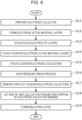
- Fig. 6 is a flow chart showing a method for manufacturing a battery 1 according to the present embodiment.
- the method for manufacturing a battery 1 as described below is an example, and the method for manufacturing a battery 1 is not limited to the following example.
- the method for manufacturing a battery 1 includes (1) a power-generating element laminating step (steps S11 to S14), (2) a counter-electrode collector laminating step (steps S15 to S17), (3) a cutting step (step S18), and (4) an insulating layer forming step (step S19). The following describes each of these steps in detail.
- an electrode collector 11 is prepared (step S11).
- power-generating elements composed of electrode active material layers 12, solid electrolyte layers 30, and counter-electrode active material layers 22 are laminated in this order on both principal surfaces 11a and 11b of the electrode collector 11 thus prepared (steps S12, S13, and S14).
- a heat treatment and/or a high-pressure press process is/are performed in each step on an as-needed basis. This gives a laminated polar plate in which the power-generating elements are laminated on both principal surfaces 11a and 11b of the electrode collector 11.
- regions 51a and 51b not covered with the electrode active material layers 12 are formed at ends of the principal surfaces 11a and 11b, respectively, of the electrode collector 11. That is, the electrode active material layers 12 are not formed entirely on the principal surfaces 11a and 11b of the electrode collector 11 but formed so that only ends are exposed. This makes it possible to easily form a projecting portion 13 of the electrode collector 11 in a subsequent step.
- the electrode active material layers 12 may be formed to entirely cover the principal surfaces 11a and 11b.
- a step of exposing the ends of the principal surfaces 11a and 11b needs only be executed.
- the electrode active material layer 12, the solid electrolyte layer 30, and the counter-electrode active material layer 22 of each of the power-generating elements are each formed in sequence, for example, by using a wet coating method.
- the use of the wet coating method makes it possible to easily laminate the power-generating element on the electrode collector 11.
- Usable examples of the wet coating method include, but are not limited to, coating methods such as a die coating method, a doctor blade method, a roll coater method, a screen printing method, and an inkjet method.
- a paint-making step is executed in which slurries are obtained separately by appropriately mixing together each of the materials that form the electrode active material layer 12, the solid electrolyte layer 30, and the counter-electrode active material layer 22 and a solvent.
- a publicly-known solvent that is used in fabricating a publicly-known all-solid battery such as a lithium-ion all-solid battery may be used.
- the slurries, obtained in the paint-making step, of the respective layers are applied over the electrode collector 11.
- This layered coating is executed in the order of the electrode active material layer 12, the solid electrolyte layer 30, and then the counter-electrode active material layer 22.
- the overlaying of a layer being overlaid first may be followed by the overlaying of a next layer.
- the overlaying of the next layer may be started during the overlaying of the layer being overlaid first. That is, steps S12, S13, and S14 may be simultaneously executed in parallel.
- the slurries of the respective layers are sequentially applied, and after all layers have been applied, a heat treatment that removes the solvents and the binder materials and a high-pressure press process that accelerates the filling of the materials of the respective layers are executed, for example.
- the heat treatment and the high-pressure press process may be executed each time a layer is overlaid.
- the heat treatment and the high-pressure press process may be executed each time one layer is overlaid, may be executed separately after any two layers have been overlaid and after one layer has been overlaid, or may be executed all at once after all three layers have been overlaid.
- the high-pressure press process involves the use of, for example, a roll press, a flat-plate press, or other presses. It should be noted that at least one of the heat treatment and the high-pressure press process may not be performed.
- Performing a layered coating method in this way makes it possible to improve the bondability of the interface between each of the layers, namely the electrode collector 11, the electrode active material layer 12, the solid electrolyte layer 30, and the counter-electrode active material layer 22, and another and reduce interface resistance, and also makes it possible to improve the bondability between the powder materials used in the electrode active material layer 12, the solid electrolyte layer 30, and the counter-electrode active material layer 22 and reduce grain boundary resistivity. That is, favorable interfaces are formed between each of the layers of the power-generating element and another and between each of the powder materials contained in the respective layers and another.
- the power-generating element laminating step may be performed in a series of continuous processes such as roll-to-roll processes.
- counter-electrode collector laminating step counter-electrode collectors 21 are laminated on both surfaces of the laminated polar plate in which the power-generating elements are laminated on both surfaces of the electrode collector 11 (step S15). Specifically, the counter-electrode collectors 21 are laminated on a principal surface 22a of an upper one of the counter-electrode active material layers 22 and a principal surface 22b of a lower one of the counter-electrode active material layers 22, respectively. In so doing, bonding is done by a high-pressure press process or other processes (step S16).
- step S17 removal of ends of the counter-electrode collectors 21 is performed so that the counter-electrode active material layers 22 become exposed at ends of a side from which the electrode collector 11 is to project. In this way, a unit cell 2 shown in Fig. 2 is formed.
- At least part of the removal is performed by cutting with a knife, a laser, or a jet.
- parts of the counter-electrode active material layers 22, the solid electrolyte layers 30, and the electrode active material layers 12 may be simultaneously removed.
- the cutting is performed just short of the electrode collector 11 so that the electrode collector 11, which is to project, is not cut off.
- the cutting may be replaced by polishing, laser trimming, plasma etching, or chemical etching.
- the removal may be performed by a combination of these processes. The way in which the removal is performed is not limited to these processes.
- ends of the counter-electrode active material layers 22, the solid electrolyte layers 30, and the electrode active material layers 12 are removed, for example, by cutting just short of the electrode collector 11 or polishing. This makes it possible to expose the ends of the principal surfaces 11a and 11b of the electrode collector 11 to form the regions 51a and 51b.
- counter-electrode collectors 21 molded in advance into desired dimensions may be prepared, laminated on both surfaces of the laminated polar plate in which the power-generating elements are laminated on both surfaces of the electrode collector 11, and bonded together by a high-pressure press process or other processes.
- the step of removing parts of the counter-electrode collectors (step S17) may be omitted.
- an end of the unit cell 2 is cut so that the projecting portion 13 of the electrode collector 11 remains (step S18). Specifically, any part or the whole of a side other than the side on which the projecting portion 13 is provided is cut with a knife, a laser, a jet, or other means.
- the electrode collector 11, the electrode active material layers 12, the solid electrolyte layers 30, the counter-electrode active material layers 22, and the counter-electrode collectors 21 are laminated, and they are all cut at once. This makes it unnecessary to laminate the layers of the power-generating elements in shapes into which they have been cut, thus making it possible to easily manufacture the battery 1.
- side surfaces of the electrode collector 11, the electrode active material layers 12, the solid electrolyte layers 30, the counter-electrode active material layers 22, and the counter-electrode collectors 21 are exposed. After the cutting, the side surfaces thus exposed may be protected by placing a sealing member that covers the side surfaces. That is, in a case where the side surfaces are covered with another member such as the sealing member, the side surfaces thus exposed may be covered with another member.
- an insulating layer 40 is formed so as to cover the side surfaces 12c of the electrode active material layers 12, the side surfaces 30c of the solid electrolyte layers 30, the side surfaces 22c of the counter-electrode active material layers 22, and the side surfaces 21c of the counter-electrode collectors 21 at the ends of the side from which the electrode collector 11 is to project (step S19).
- the insulating layer 40 is placed, for example, by curing a coating of a flowable resin material. The coating is performed by inkjet or screen printing or by dipping an end face of the unit cell into the resin material. The curing is performed by drying, heating, photoirradiation, or other processes, depending on the resin material used.
- the projecting portion 13 of the electrode collector 11 may be protected by masking with a tape or other material or resist processing so that the projecting portion 13 is not insulated.
- the electrical conductivity of the projecting portion 13 can be secured by, after the placement of the insulating layer 40, removing a member that protects the projecting portion 13.
- the method for manufacturing a battery 1 according to the present embodiment is not limited to the aforementioned example but may for example be the following manufacturing method.
- an electrode collector 11 having a shape shown in Figs. 1 and 2 is prepared. Then, an application process or other processes are used to laminate electrode active material layers 12 and solid electrolyte layers 30 in this order by layered coating over the electrode collector 11 in shapes shown in Figs. 1 and 2 , whereby an electrode plate is obtained.
- counter-electrode collectors 21 each having a shape shown in Figs. 1 and 2 are prepared. Then, an application process or other processes are used to laminate counter-electrode active material layers 22 and solid electrolyte layers 30 in this order by layered coating over the counter-electrode collectors 21 in shapes shown in Figs. 1 and 2 , whereby counter-electrode plates are obtained.
- the electrode plate thus obtained and the counter-electrode plates thus obtained are laminated such that the solid electrolyte layers 30 of the electrode plate and the solid electrolyte layers 30 of the counter-electrode plates make contact with each other.
- the laminated body thus laminated i.e., a unit cell 2
- a battery 1 is obtained by performing the removal of parts of the counter-electrode collectors 21 (step S17), the cutting of part of the unit cell 2 (step S18), and the formation of an insulating layer 40 (step S19).
- a battery 1A shown in Fig. 3 can be formed.
- step S12 regions 53a and 53b not covered with the electrode active material layers 12 are formed at ends at the side of the side surface 11d of the electrode collector 11 as well as the side of the side surface 11c. Further, in step S17, ends at the side of side surfaces 21d of the counter-electrode collectors 21 as well as the side of the side surfaces 21c are removed. This makes it possible to form a battery 1B shown in Figs. 4 and 5 .
- Embodiment 2 describes a laminated battery in which unit cells of batteries according to Embodiment 1 are laminated. The following gives a description with a focus on differences from Embodiment 1, and omits or simplifies a description of common features.
- Fig. 7 is a schematic cross-sectional view showing an example of a laminated battery 101 according to the present embodiment.
- the laminated battery 101 includes a plurality of unit cells 3.
- the plurality of unit cells 3 are laminated along a direction of laminating of layers that constitute each unit cell.
- the plurality of unit cells 3 are electrically connected in parallel to one another.
- the plurality of unit cells 3 are identical in configuration to one another.
- Each of the unit cells 3 differs from the unit cell 2 according to Embodiment 1 in that the unit cell 3 includes counter-electrode layers 20B and 120 instead of the two counter-electrode layers 20.
- the counter-electrode layer 20B is identical to the counter-electrode layers 20B of the battery 1B according to Modification 2 of Embodiment 1.
- each of the unit cells 3 includes an insulating layer 41.
- the counter-electrode layer 120 includes a counter-electrode collector 121 and a counter-electrode active material layer 22. At an end of the counter-electrode collector 121, there is provided a region not covered with the counter-electrode active material layer 22.
- the counter-electrode collector 121 projects from an outer surface 41d of the insulating layer 41. That is, the counter-electrode collector 121 includes a projecting portion 123 that projects outward from the outer surface 41d. A region not covered with the insulating layer 41 in planar view is equivalent to the projecting portion 123.
- the insulating layer 41 reduces exposure of the electrode active material layers 12 and the counter-electrode active material layers 22. This reduces the occurrence of damage, a short circuit, or other failures due to contact of the electrode active material layers 12 and the counter-electrode active material layers 22 with other members. This makes it possible to enhance the reliability of the laminated battery 101.
- the projecting portion 13 of the electrode collector 11 and the projecting portion 123 of the counter-electrode collector 121 are provided on different side surfaces of the laminated battery 101.
- the side surface on which the projecting portion 13 is provided and the side surface on which the projecting portion 123 is provided are side surfaces opposite to each other. This makes it possible to separate the projecting portion 13 and the projecting portion 123 from each other, making it possible to reduce the occurrence of a short circuit or other failures due to contact.
- the counter-electrode collectors 21B and 121 recede from the counter-electrode active material layers 22. This reduces the occurrence of an end face short circuit due to contact between each of the counter-electrode collectors 21B and 121 and the electrode active material layers 12 or the electrode collector 11. Further, the provision of the insulating layer 40 reduces exposure of the electrode active material layers 12 and the counter-electrode active material layers 22. This reduces the occurrence of damage, a short circuit, or other failures due to contact of the electrode active material layers 12 and the counter-electrode active material layers 22 with other members. This makes it possible to enhance the reliability of the laminated battery 101.
- the number of unit cells 3 that are laminated is 4, the number may be 2 or 3 or may be larger than or equal to 5.
- Two adjacent ones of the unit cells 3 do not share a collector with each other. That is, two counter-electrode collectors 21B and 121 of the same polarity are laid on top of each other. At this point in time, an adhesion layer may be provided between the collectors. It is desirable that the adhesion layer have high electrical conductivity.
- each of the unit cells 3 may include a counter-electrode collector 121 instead of the counter-electrode collector 21B. That is, two counter-electrode collectors 121 may be laid on top of each other.
- a method for manufacturing a laminated battery according to the present embodiment is described with reference to flow charts shown in Figs. 8A and 8B .
- the method for manufacturing a laminated battery 101 as described below is an example, and the method for manufacturing a laminated battery 101 is not limited to the following example.
- the method for manufacturing a laminated battery 101 includes (1) a power-generating element laminating step (steps S21 to S24), (2) a counter-electrode collector laminating step (steps S25 to S27), (3) a cutting step (step S28), (4) an insulating layer forming step (step S29), and (5) a unit cell laminating step (step S30).
- step S28 and preceding steps constitute a process of manufacturing a unit cell.
- the power-generating element laminating step i.e., steps S21, S22, S23, and S24, is not described here, as these steps are identical to steps S11, S12, S13, and S14 of the manufacturing method according to Embodiment 1.
- the counter-electrode collector laminating step and the subsequent steps are described in detail below.
- counter-electrode collectors 21B and 121 are laminated on both surfaces of the laminated polar plate in which the power-generating elements are laminated on both surfaces of the electrode collector 11 (step S25). Specifically, the counter-electrode collectors 21B is laminated on a principal surface 22a of an upper one of the counter-electrode active material layers 22. The counter-electrode collector 121 is laminated on a principal surface 22b of a lower one of the counter-electrode active material layers 22. In so doing, bonding is done by a high-pressure press process or other processes (step S26).
- step S27 removal of ends of the counter-electrode collectors 21B and 121 is performed so that the counter-electrode active material layers 22 become exposed at ends of a side from which the electrode collector 11 is to project. In this way, a unit cell 3 shown in Fig. 7 is formed.
- At least part of the removal is performed by cutting with a knife, a laser, or a jet.
- parts of the counter-electrode active material layers 22, the solid electrolyte layers 30, and the electrode active material layers 12 may be simultaneously removed.
- the cutting is performed just short of the electrode collector 11 so that the electrode collector 11, which is to project, is not cut off.
- the cutting may be replaced by polishing, laser trimming, plasma etching, or chemical etching.
- the removal may be performed by a combination of these processes. The way in which the removal is performed is not limited to these processes.
- removal of ends of the counter-electrode collector 21B is performed so that only one counter-electrode active material layer 22 of the unit cell 3 becomes exposed at an end of a side from which the counter-electrode collector 121 is to project.
- the removal of the ends of the counter-electrode collector 21B is performed so that the upper counter-electrode active material layer 22 becomes exposed.
- At least part of the removal is performed by cutting with a knife, a laser, or a jet. In so doing, parts of the counter-electrode active material layers 22, the solid electrolyte layers 30, and the electrode active material layers 12, and the electrode collector 11 may be simultaneously removed.
- the cutting is performed just short of the counter-electrode collector 121 so that the counter-electrode collector 121, which is to project, is not cut off.
- the cutting may be replaced by polishing, laser trimming, plasma etching, or chemical etching.
- the removal may be performed by a combination of these processes. The way in which the removal is performed is not limited to these processes.
- counter-electrode collectors 21B and 121 molded in advance into desired dimensions may be prepared, laminated on both surfaces of the laminated polar plate in which the power-generating elements are laminated on both surfaces of the electrode collector 11, and bonded together by a high-pressure press process or other processes.
- the step of removing part of the counter-electrode collector 21B or 121 may be omitted.
- step S28 ends of the unit cell 3 are cut so that the projecting portion 13 of the electrode collector 11 and a projecting portion 123 of the counter-electrode collector 121 remain (step S28). Specifically, any part or the whole of a side other than the sides on which the projecting portion 13 is provided and the sides on which the projecting portion 123 is provided is cut with a knife, a laser, a jet, or other means.
- the electrode collector 11, the electrode active material layers 12, the solid electrolyte layers 30, the counter-electrode active material layers 22, and the counter-electrode collectors 21B and 121 are laminated, and they are all cut at once. This makes it unnecessary to laminate the layers of the power-generating elements in shapes into which they have been cut, thus making it possible to easily manufacture the unit cell 3.
- side surfaces of the electrode collector 11, the electrode active material layers 12, the solid electrolyte layers 30, the counter-electrode active material layers 22, and the counter-electrode collectors 21B and 121 are exposed. After the cutting, the side surfaces thus exposed may be protected by placing a sealing member that covers the side surfaces. That is, in a case where the side surfaces are covered with another member such as the sealing member, the side surfaces thus exposed may be covered with another member.
- an insulating layer 40 is formed so as to cover the side surfaces 12c of the electrode active material layers 12, the side surfaces 30c of the solid electrolyte layers 30, the side surfaces 22c of the counter-electrode active material layers 22, and the side surfaces 21c of the counter-electrode collectors 21B and 121 at the ends of the side from which the electrode collector 11 is to project (step S29).
- an insulating layer 41 is formed so as to cover the side surface 21d of the counter-electrode collector 21B, the side surfaces 22d of the counter-electrode active material layers 22, the side surfaces 30d of the solid electrolyte layers 30, the side surfaces 12d of the electrode active material layers 12, and the side surface 11d of the electrode collector 11 at the end of the side from which the counter-electrode collector 121 is to project.
- the insulating layers 40 and 41 are each placed, for example, by curing a coating of a flowable resin material. The coating is performed by inkjet or screen printing or by dipping an end face of the unit cell into the resin material. The curing is performed by drying, heating, photoirradiation, or other processes, depending on the resin material used.
- the projecting portion 13 of the electrode collector 11 and the projecting portion 123 of the counter-electrode collector 121 may be protected by masking with a tape or other material or resist processing so that the projecting portions 13 and 123 are not insulated.
- the electrical conductivity of the projecting portions 13 and 123 can be secured by, after the placement of the insulating layers 40 and 41, removing members that protect the projecting portions 13 and 123.
- the unit cell laminating step is described.
- a plurality of the unit cells 3 are laminated in the same orientation (step S30).
- the unit cells 3 are bonded together so that a surface at which a counter-electrode active material layer 22 is exposed and a surface at which a counter-electrode active material layer 22 is not exposed are adjacent to each other.
- the unit cells 3 are bonded together by the coating of an adhesive or the laminating of adhesive films, the way in which the unit cells 3 are bonded together is not limited to these processes. Further, the bonding may be followed by a heat-treatment or pressing step.
- step S30 the step of laminating unit cells (step S30) may be followed by the step of forming insulating layers 40 and 41 (step S29).
- the battery is constituted by an electrode collector, an electrode active material layer, a solid electrolyte layer, and a counter-electrode active material layer, a counter-electrode collector, and an insulating layer, this is not intended to impose any limitation.
- a bonding layer or other layers for reducing electric resistance and improving bonding strength may be provided between each of the layers of the battery and another.
- the battery may not include a collector on the counter-electrode active material layer in a case where the battery is surrounded by a chassis or substrate and a portion of the chassis or substrate functions as a collector.
- the counter-electrode layer may be constituted by the counter-electrode active material layer.
- the electrode active material layer, the solid electrolyte layer, and the counter-electrode active material layer are identical in shape and position to one another in planar view, this is not intended to impose any limitation. At least one of the electrode active material layer, the solid electrolyte layer, and the counter-electrode active material layer may be different in shape or position in planar view.
- a power-generating element is formed by sequentially laminating the electrode active material layer, the solid electrolyte layer, and the counter-electrode active material layer over the collector in the power-generating element laminating step, this is not intended to impose any limitation.
- a power-generating element may be formed by sequentially laminating the electrode active material layer, the solid electrolyte layer, and the counter-electrode active material layer over a sheet-like substrate, and the power-generating element thus formed may be removed from the substrate and laminated on the electrode collector.
- a battery according to the present disclosure may be used as a secondary battery such as an all-solid battery for use, for example, in various types of electronics, electrical appliances, automobiles, or other devices.
Landscapes
- Chemical & Material Sciences (AREA)
- Chemical Kinetics & Catalysis (AREA)
- Electrochemistry (AREA)
- General Chemical & Material Sciences (AREA)
- Engineering & Computer Science (AREA)
- Manufacturing & Machinery (AREA)
- Materials Engineering (AREA)
- Physics & Mathematics (AREA)
- Condensed Matter Physics & Semiconductors (AREA)
- General Physics & Mathematics (AREA)
- Inorganic Chemistry (AREA)
- Secondary Cells (AREA)
- Battery Electrode And Active Subsutance (AREA)
Applications Claiming Priority (2)
| Application Number | Priority Date | Filing Date | Title |
|---|---|---|---|
| JP2021104756 | 2021-06-24 | ||
| PCT/JP2022/018146 WO2022270142A1 (fr) | 2021-06-24 | 2022-04-19 | Batterie |
Publications (2)
| Publication Number | Publication Date |
|---|---|
| EP4362155A1 true EP4362155A1 (fr) | 2024-05-01 |
| EP4362155A4 EP4362155A4 (fr) | 2025-06-18 |
Family
ID=84545624
Family Applications (1)
| Application Number | Title | Priority Date | Filing Date |
|---|---|---|---|
| EP22828061.6A Pending EP4362155A4 (fr) | 2021-06-24 | 2022-04-19 | Batterie |
Country Status (5)
| Country | Link |
|---|---|
| US (1) | US20240128620A1 (fr) |
| EP (1) | EP4362155A4 (fr) |
| JP (1) | JPWO2022270142A1 (fr) |
| CN (1) | CN117529840A (fr) |
| WO (1) | WO2022270142A1 (fr) |
Families Citing this family (1)
| Publication number | Priority date | Publication date | Assignee | Title |
|---|---|---|---|---|
| US20250105472A1 (en) * | 2023-09-23 | 2025-03-27 | GM Global Technology Operations LLC | Insulating coating for improving lithium-ion battery quality |
Family Cites Families (8)
| Publication number | Priority date | Publication date | Assignee | Title |
|---|---|---|---|---|
| WO2015173686A1 (fr) | 2014-05-16 | 2015-11-19 | Semiconductor Energy Laboratory Co., Ltd. | Dispositif électronique avec batterie secondaire |
| JP6915587B2 (ja) * | 2018-05-09 | 2021-08-04 | トヨタ自動車株式会社 | 積層電池の製造方法 |
| JP7172127B2 (ja) * | 2018-05-14 | 2022-11-16 | トヨタ自動車株式会社 | 全固体電池及びその製造方法 |
| JP2020013729A (ja) | 2018-07-19 | 2020-01-23 | トヨタ自動車株式会社 | 直列積層型全固体電池の製造方法 |
| KR102303678B1 (ko) * | 2019-02-12 | 2021-09-16 | 도요타 지도샤(주) | 전고체 전지 적층체 |
| JP7562947B2 (ja) * | 2019-02-12 | 2024-10-08 | トヨタ自動車株式会社 | 全固体電池積層体 |
| CN115298897B (zh) * | 2020-03-25 | 2026-04-14 | 松下知识产权经营株式会社 | 电池 |
| JP7331799B2 (ja) * | 2020-07-20 | 2023-08-23 | トヨタ自動車株式会社 | 全固体電池の製造方法 |
-
2022
- 2022-04-19 CN CN202280043290.0A patent/CN117529840A/zh active Pending
- 2022-04-19 EP EP22828061.6A patent/EP4362155A4/fr active Pending
- 2022-04-19 WO PCT/JP2022/018146 patent/WO2022270142A1/fr not_active Ceased
- 2022-04-19 JP JP2023529651A patent/JPWO2022270142A1/ja active Pending
-
2023
- 2023-12-08 US US18/533,254 patent/US20240128620A1/en active Pending
Also Published As
| Publication number | Publication date |
|---|---|
| JPWO2022270142A1 (fr) | 2022-12-29 |
| WO2022270142A1 (fr) | 2022-12-29 |
| CN117529840A (zh) | 2024-02-06 |
| US20240128620A1 (en) | 2024-04-18 |
| EP4362155A4 (fr) | 2025-06-18 |
Similar Documents
| Publication | Publication Date | Title |
|---|---|---|
| US20230009792A1 (en) | Battery | |
| US12051816B2 (en) | Laminated battery | |
| US20220302462A1 (en) | Battery | |
| WO2021009959A1 (fr) | Batterie | |
| CN110534667A (zh) | 电池 | |
| US12074292B2 (en) | Laminated battery | |
| US20230024599A1 (en) | Battery | |
| US20240258666A1 (en) | Battery and method for manufacturing battery | |
| US20240213495A1 (en) | Battery and method for manufacturing battery | |
| US20240128620A1 (en) | Battery | |
| US20230307717A1 (en) | Battery, laminated battery, and method for manufacturing same | |
| US20240106004A1 (en) | Battery and method for manufacturing battery | |
| WO2025243576A1 (fr) | Batterie | |
| US12315868B2 (en) | Method for manufacturing battery | |
| CN118575358A (zh) | 电池及电池的制造方法 | |
| CN117425997A (zh) | 电池以及电池的制造方法 | |
| US20240222809A1 (en) | Battery and method for manufacturing battery | |
| EP4738522A1 (fr) | Batterie et procédé de fabrication de batterie | |
| CN116636030A (zh) | 电池、层叠电池及其制造方法 | |
| WO2025263027A1 (fr) | Batterie | |
| JP2026003429A (ja) | 電池 | |
| WO2025263026A1 (fr) | Batterie | |
| WO2025243578A1 (fr) | Batterie et procédé de fabrication de batterie |
Legal Events
| Date | Code | Title | Description |
|---|---|---|---|
| STAA | Information on the status of an ep patent application or granted ep patent |
Free format text: STATUS: THE INTERNATIONAL PUBLICATION HAS BEEN MADE |
|
| PUAI | Public reference made under article 153(3) epc to a published international application that has entered the european phase |
Free format text: ORIGINAL CODE: 0009012 |
|
| STAA | Information on the status of an ep patent application or granted ep patent |
Free format text: STATUS: REQUEST FOR EXAMINATION WAS MADE |
|
| 17P | Request for examination filed |
Effective date: 20231221 |
|
| AK | Designated contracting states |
Kind code of ref document: A1 Designated state(s): AL AT BE BG CH CY CZ DE DK EE ES FI FR GB GR HR HU IE IS IT LI LT LU LV MC MK MT NL NO PL PT RO RS SE SI SK SM TR |
|
| DAV | Request for validation of the european patent (deleted) | ||
| DAX | Request for extension of the european patent (deleted) | ||
| REG | Reference to a national code |
Ref country code: DE Ref legal event code: R079 Free format text: PREVIOUS MAIN CLASS: H01M0010052000 Ipc: H01M0004640000 |
|
| A4 | Supplementary search report drawn up and despatched |
Effective date: 20250516 |
|
| RIC1 | Information provided on ipc code assigned before grant |
Ipc: H01M 50/591 20210101ALI20250512BHEP Ipc: H01M 50/586 20210101ALI20250512BHEP Ipc: H01M 10/0585 20100101ALI20250512BHEP Ipc: H01M 10/0562 20100101ALI20250512BHEP Ipc: H01M 10/0525 20100101ALI20250512BHEP Ipc: H01M 10/052 20100101ALI20250512BHEP Ipc: H01M 4/64 20060101AFI20250512BHEP |