EP4362607A2 - Dispositif de chauffage électrique avec un serre-flan - Google Patents
Dispositif de chauffage électrique avec un serre-flan Download PDFInfo
- Publication number
- EP4362607A2 EP4362607A2 EP23205382.7A EP23205382A EP4362607A2 EP 4362607 A2 EP4362607 A2 EP 4362607A2 EP 23205382 A EP23205382 A EP 23205382A EP 4362607 A2 EP4362607 A2 EP 4362607A2
- Authority
- EP
- European Patent Office
- Prior art keywords
- heating device
- hold
- electric heating
- moisture
- channel
- Prior art date
- Legal status (The legal status is an assumption and is not a legal conclusion. Google has not performed a legal analysis and makes no representation as to the accuracy of the status listed.)
- Pending
Links
Images

Classifications
-
- F—MECHANICAL ENGINEERING; LIGHTING; HEATING; WEAPONS; BLASTING
- F24—HEATING; RANGES; VENTILATING
- F24H—FLUID HEATERS, e.g. WATER OR AIR HEATERS, HAVING HEAT-GENERATING MEANS, e.g. HEAT PUMPS, IN GENERAL
- F24H3/00—Air heaters
- F24H3/02—Air heaters with forced circulation
- F24H3/04—Air heaters with forced circulation the air being in direct contact with the heating medium, e.g. electric heating element
- F24H3/0405—Air heaters with forced circulation the air being in direct contact with the heating medium, e.g. electric heating element using electric energy supply, e.g. the heating medium being a resistive element; Heating by direct contact, i.e. with resistive elements, electrodes and fins being bonded together without additional element in-between
- F24H3/0429—For vehicles
-
- H—ELECTRICITY
- H05—ELECTRIC TECHNIQUES NOT OTHERWISE PROVIDED FOR
- H05B—ELECTRIC HEATING; ELECTRIC LIGHT SOURCES NOT OTHERWISE PROVIDED FOR; CIRCUIT ARRANGEMENTS FOR ELECTRIC LIGHT SOURCES, IN GENERAL
- H05B3/00—Ohmic-resistance heating
- H05B3/20—Heating elements having extended surface area substantially in a two-dimensional [2D] plane, e.g. plate-heater
- H05B3/22—Heating elements having extended surface area substantially in a two-dimensional [2D] plane, e.g. plate-heater non-flexible
- H05B3/24—Heating elements having extended surface area substantially in a two-dimensional [2D] plane, e.g. plate-heater non-flexible heating conductor being self-supporting
-
- F—MECHANICAL ENGINEERING; LIGHTING; HEATING; WEAPONS; BLASTING
- F24—HEATING; RANGES; VENTILATING
- F24H—FLUID HEATERS, e.g. WATER OR AIR HEATERS, HAVING HEAT-GENERATING MEANS, e.g. HEAT PUMPS, IN GENERAL
- F24H9/00—Details
- F24H9/20—Arrangement or mounting of control or safety devices
-
- F—MECHANICAL ENGINEERING; LIGHTING; HEATING; WEAPONS; BLASTING
- F24—HEATING; RANGES; VENTILATING
- F24H—FLUID HEATERS, e.g. WATER OR AIR HEATERS, HAVING HEAT-GENERATING MEANS, e.g. HEAT PUMPS, IN GENERAL
- F24H1/00—Water heaters, e.g. boilers, continuous-flow heaters or water-storage heaters
- F24H1/0072—Special adaptations
- F24H1/009—Special adaptations for vehicle systems
-
- F—MECHANICAL ENGINEERING; LIGHTING; HEATING; WEAPONS; BLASTING
- F24—HEATING; RANGES; VENTILATING
- F24H—FLUID HEATERS, e.g. WATER OR AIR HEATERS, HAVING HEAT-GENERATING MEANS, e.g. HEAT PUMPS, IN GENERAL
- F24H1/00—Water heaters, e.g. boilers, continuous-flow heaters or water-storage heaters
- F24H1/10—Continuous-flow heaters, i.e. heaters in which heat is generated only while the water is flowing, e.g. with direct contact of the water with the heating medium
- F24H1/12—Continuous-flow heaters, i.e. heaters in which heat is generated only while the water is flowing, e.g. with direct contact of the water with the heating medium in which the water is kept separate from the heating medium
- F24H1/121—Continuous-flow heaters, i.e. heaters in which heat is generated only while the water is flowing, e.g. with direct contact of the water with the heating medium in which the water is kept separate from the heating medium using electric energy supply
-
- F—MECHANICAL ENGINEERING; LIGHTING; HEATING; WEAPONS; BLASTING
- F24—HEATING; RANGES; VENTILATING
- F24H—FLUID HEATERS, e.g. WATER OR AIR HEATERS, HAVING HEAT-GENERATING MEANS, e.g. HEAT PUMPS, IN GENERAL
- F24H3/00—Air heaters
- F24H3/02—Air heaters with forced circulation
- F24H3/04—Air heaters with forced circulation the air being in direct contact with the heating medium, e.g. electric heating element
- F24H3/0405—Air heaters with forced circulation the air being in direct contact with the heating medium, e.g. electric heating element using electric energy supply, e.g. the heating medium being a resistive element; Heating by direct contact, i.e. with resistive elements, electrodes and fins being bonded together without additional element in-between
- F24H3/0429—For vehicles
- F24H3/0452—Frame constructions
-
- F—MECHANICAL ENGINEERING; LIGHTING; HEATING; WEAPONS; BLASTING
- F24—HEATING; RANGES; VENTILATING
- F24H—FLUID HEATERS, e.g. WATER OR AIR HEATERS, HAVING HEAT-GENERATING MEANS, e.g. HEAT PUMPS, IN GENERAL
- F24H9/00—Details
- F24H9/20—Arrangement or mounting of control or safety devices
- F24H9/2007—Arrangement or mounting of control or safety devices for water heaters
- F24H9/2014—Arrangement or mounting of control or safety devices for water heaters using electrical energy supply
- F24H9/2028—Continuous-flow heaters
-
- F—MECHANICAL ENGINEERING; LIGHTING; HEATING; WEAPONS; BLASTING
- F24—HEATING; RANGES; VENTILATING
- F24H—FLUID HEATERS, e.g. WATER OR AIR HEATERS, HAVING HEAT-GENERATING MEANS, e.g. HEAT PUMPS, IN GENERAL
- F24H9/00—Details
- F24H9/20—Arrangement or mounting of control or safety devices
- F24H9/2064—Arrangement or mounting of control or safety devices for air heaters
- F24H9/2071—Arrangement or mounting of control or safety devices for air heaters using electrical energy supply
-
- F—MECHANICAL ENGINEERING; LIGHTING; HEATING; WEAPONS; BLASTING
- F26—DRYING
- F26B—DRYING SOLID MATERIALS OR OBJECTS BY REMOVING LIQUID THEREFROM
- F26B5/00—Drying solid materials or objects by processes not involving the application of heat
- F26B5/16—Drying solid materials or objects by processes not involving the application of heat by contact with sorbent bodies, e.g. absorbent mould; by admixture with sorbent materials
Definitions
- the present invention relates to an electric heating device, having a circulation chamber with inlet and outlet openings for a heat carrier, a heating device connected to the circulation chamber in a heat-conducting manner, in particular a PTC heating device with a PTC element, for heating the heat carrier in the circulation chamber, a connection chamber with a control device arranged therein and comprising a circuit board for controlling the heating device, a partition between the circulation chamber and the connection chamber, and a hold-down device arranged on the side of the control device facing away from the partition, which cooperates with the control device, for example pressing the control device in the direction of the partition.
- the EP 2 466 989 A1 discloses a generic electric heating device.
- the hold-down device called the supporting structure, interacts with the control device in that the hold-down device indirectly presses on the control device so that it rests better on the side of the partition wall and can release waste heat to the partition wall.
- connection chamber can contain moisture, for example in the air it contains, i.e. air humidity. Temperature fluctuations, in particular temperature gradients, within the connection chamber can cause at least some of this moisture to condense and then settle in liquid form in the connection chamber. When the heating device is in operation, such temperature fluctuations or temperature gradients can occur because an area close to the heating device, in particular near the partition wall, can be heated quickly. In particular, a wall or a cover away from the partition wall or the heating device can then have a comparatively low temperature and this can lead to the moisture condensing out. If the control device comes into contact with moisture - in particular in liquid form - there is a risk of the control device becoming defective.
- the present invention is based on the problem of improving the protection of the control device in the electric heating device, in particular protecting it from moisture.
- the present invention proposes an electric heating device with the features of claim 1.
- Advantageous further developments are the subject matter of the subclaims.
- the hold-down device has means for collecting moisture, which are designed in such a way that condensed moisture is kept away from the control device at least in some areas. These means can catch the moisture dripping towards the control device and collect it and drain it away to the side next to the hold-down device. The moisture is accordingly collected on the side facing away from the control device. The moisture is initially held back on the side of the hold-down device and then collected and discharged in one or more specific areas on or next to the control device. The collection can alternatively or additionally take place by collecting the moisture using the hold-down device and storing or saving it there. It has been shown that a corresponding reservoir, for example one containing a drying agent, is emptied again by the operation of the electric heating device.
- the reservoir can absorb the moisture and release it again due to the heating of the electric heating device during operation.
- the drying agent is regenerated by the operation of the electric heating device.
- the reservoir is dimensioned such that it can store the condensate that usually occurs within the connection chamber.
- These means preferably comprise a gutter and/or a roof surface to keep moisture away from the control device.
- an improved heating device is proposed in which - in particular on a comparatively cold cover or a cold wall - condensed water and/or air humidity can be better kept away from the control device. This can be achieved by protecting the control device from contact with moisture by means of the gutter located on or in the hold-down device and/or the roof surface.
- the hold-down device extends at least over a certain surface area of the control device, usually the circuit board, such that the areas of the control device that are particularly susceptible to moisture are covered by the hold-down device.
- the hold-down device is preferably located in a manner known per se between the control device and the cover, which usually extends parallel to the partition wall. According to the present invention, condensed moisture dripping from the cover is collected and removed and/or stored by the hold-down device, and in any case removed from those surface areas of the circuit board that are particularly susceptible to moisture. These include, for example, soldering surfaces or points or contact points exposed on the circuit board, in particular for contacting the power current, which can have a voltage of well over 200 V up to 800 V or more.
- the electrical heating device is usually aligned in the earth's gravitational field such that the hold-down device is provided above the control device.
- the cover or another wall of the connection chamber may be located above the hold-down device.
- the invention has shown that the hold-down device can be used additionally to protect the heating device or the control device from moisture.
- the typical function of the hold-down device - pressing the control device - is supplemented by a function of directing liquid in the gutter and/or holding back drops by means of the roof surface that at least partially covers the control device.
- a previously known hold-down device can be supplemented with features according to the invention or described here and the heating device can be improved.
- connection chamber can be closed via a/the wall or a/the cover of the electrical heating device.
- the wall ensures in particular and at least essentially that the connection chamber is sealed and that the hold-down device is pressed.
- the wall can have an embossing.
- the embossing can correspond to the hold-down device, in particular to the channel, in order to form a positive connection with it.
- the embossing can serve to stabilize the wall.
- the gutter and/or roof surface can effectively drain or keep moisture away from the control device.
- the gutter can be used to direct the moisture. For example, to areas that are less susceptible to moisture, such as an area away from the control device. Drops that might otherwise have landed on the control device can land on the roof surface.
- the hold-down device can therefore take on a dual function if the gutter or roof surface according to the invention is added to the hold-down device: It can press on the control device to improve its cooling and it can protect the control device from moisture.
- a or the channel can be U-shaped or V-shaped in cross-section.
- the channel is open in one direction in cross-section, so that liquid can be introduced into the channel from at least this direction, for example to be guided by the channel. Thanks to the channel, material can also be saved on the hold-down device.
- the channel thanks to its volume, not only serves to hold off and/or guide moisture, but also in particular to store and retain moisture, for example until the moisture has evaporated again.
- a roof surface is understood to be a two-dimensionally elongated surface whose main task is to cover the control device. For example, if the ratio of the average side length of a section of the hold-down device to its thickness is in the range above 2, 3, 4 or 5, it can be referred to as a roof surface. It can be referred to as a roof surface if sections of the hold-down device are longer and wider than is actually necessary for stability reasons in order to fulfill the typical task of the hold-down device - pressing the control device.
- the roof surface and/or the gutter is preferably arranged, at least substantially and/or in sections, parallel to the circuit board. This provides the best possible protection against the Moisture can be prevented because the gutter or roof surface can protect a large distance and/or area of the circuit board.
- the flow guide for the condensate preferably formed by the hold-down device can transfer it into a reservoir of a hygroscopic drying agent due to gravity or capillary action.
- This can be formed within the connection chamber.
- the hold-down device itself.
- the roof surface can have a recess.
- This recess is preferably provided for the hygroscopic drying agent.
- the hold-down device or the recess can contain the drying agent.
- the drying agent can thereby absorb or take up the moisture contained in the air in particular.
- the recess should be large enough to accommodate the typically pourable, granular drying agent in a sufficient amount in relation to the size of the connection chamber.
- the recess can therefore catch or hold back the moisture, for example in liquid form or bound in the drying agent to be provided therein.
- roof surfaces can also be provided in order to specifically protect the control device without excessive material expenditure.
- the roof surface and/or another roof surface can have a through opening, for example for a pin, in particular for centering.
- the heat transfer medium is preferably a fluid, in particular gaseous and/or liquid.
- the heat transfer medium can comprise water, oil and/or air or at least consist essentially of these. Other substances are also conceivable.
- the invention relates to an electric heating device for heating water, oil and/or air by means of a flow through the circulation chamber.
- the hold-down device can be made of plastic and/or metal or can be made from it. Both materials can be easily manufactured in large quantities using a casting process, for example die casting or injection molding. The materials can also be manufactured using separating processes in order to achieve good tightness and precision of the gutter and/or the roof surface.
- the electric heating device is typically intended for vehicles. For example, for land vehicles, sea vehicles or aircraft.
- the roof surface and/or the recess is oriented away from the circuit board.
- the roof surface and/or the recess can be covered alternatively or additionally to fix the drying agent.
- the roof surface is typically spaced from the circuit board.
- the recess can be open away from the circuit board and closed towards the circuit board, in particular to create a possibility for accommodating drying agent.
- the drying agent can thus can be easily inserted into the heating device.
- the drying agent can also be placed precisely because the recess creates a boundary. But moisture can also be easily guided in the recess.
- the roof surface and/or the depression adjoin a first section of the gutter and a second section of the gutter.
- the roof surface or depression and the gutter are provided at the same time, particularly good protection against moisture can be offered.
- the sections usually differ in that they are aligned and/or shaped differently. Against this background, it is sensible to provide several sections of the gutter, with the depression adjoining at least two of these sections. This mechanically stabilizes the hold-down device and moisture can be held back or absorbed over a large area. The mechanical stability is particularly helpful if the roof surface is used for the drying agent.
- the channel is arranged in a/the first section facing away from the circuit board and/or is covered at least in sections to form a channel for the moisture.
- the channel faces away from the circuit board, it is designed to be closed to the circuit board and can thus guide moisture away from the circuit board and thus protect the circuit board from moisture.
- the channel can be easily covered in this arrangement, for example by a/the wall or a/the cover to close the connection chamber, for example to form the channel.
- the channel can have a second and/or a third section that is arranged facing away from the circuit board and/or is covered at least in sections to form a channel for the moisture.
- the sections usually differ in that they are aligned and/or shaped differently. This means that the moisture can be effectively kept away from the circuit board.
- the channels can also be easily covered to form the channel.
- first section, the second section and/or the third section run at least essentially straight.
- the sections can run at least essentially in one plane.
- the moisture can be absorbed from different areas in the connection chamber.
- the moisture can be guided into one or more areas of the connection chamber.
- the different areas include, for example, critical areas on the circuit board where moisture must be particularly kept out, for example in the area of power transistors and/or high-voltage components.
- the three sections merge into one another at a common interface and/or are arranged in a Y-shape or star shape and/or at an angle to one another.
- the sections can thus open up a type of funnel that can collect the moisture in liquid form.
- the moisture can be directed into a section that represents the lowest section, for example.
- the channel has a receiving area for receiving moisture in liquid form.
- the receiving area is understood to mean, for example, a lateral opening on the channel.
- the receiving area should be aligned and designed in such a way that it is designed to receive liquid, in particular flowing, located on the wall or lid of the connection chamber, into the channel.
- the receiving area can have a funnel shape and/or a recess.
- the receiving area can also be designed as an opening in the hold-down device, in particular the channel, and/or have this.
- the opening can have a capillary effect on the moisture, so that moisture in the vicinity can be drawn in by the capillary effect.
- the opening must be comparatively small, for example have a diameter of no more than 1 mm, 0.75 mm or 0.5 mm.
- the hold-down device can also have several of the openings. In particular to prevent blockages, but also to achieve a capillary effect, several openings can be provided next to one another. One or more openings can also be arranged in several or each of several sections of the channel. The opening can also be arranged at the interface between two sections. An opening can also be arranged between each pair of two sections.
- the hold-down device can then absorb moisture well in different installation positions or orientations.
- the hold-down device has a baffle wall, at least in the receiving area.
- the baffle wall is to be understood in particular in the sense of a roof surface or further roof surface, which should be spaced apart from both the circuit board and a wall or a cover of the connection chamber.
- the baffle wall can both effectively keep moisture away from the circuit board and efficiently guide moisture into the channel.
- the hold-down device can have a step at least in the receiving area.
- the step can be arranged in sections around the channel.
- the step can run around at least one, several or all sections of the channel.
- the step can, in conjunction with the wall or the cover, provide a further channel in which moisture can be retained - particularly in the receiving area.
- the channel has a dispensing area for releasing the moisture in liquid form.
- the dispensing area can be a lateral opening or recess on the channel.
- the dispensing area should be aligned and designed such that it is designed to dispense flowing liquid from the channel.
- the dispensing area can also be provided with an opening and/or with the opening described above.
- the dispensing area is provided at one end of a channel or a section. In this way, gravity can be used effectively to release moisture. This also prevents a moisture nest from building up in the channel, which can lead to corrosion.
- the hold-down device can be provided with through holes for centering the hold-down device relative to the circuit board.
- Pins can be provided for centering the hold-down device relative to the circuit board.
- the pins can protrude from the circuit board and/or the partition or be arranged on it.
- the through holes can correspond to the pins.
- the hold-down device can be fixed relative to the circuit board or relative to the partition.
- the circuit board and the hold-down device can be plugged onto the pins. This ensures that the hold-down device is arranged in the right place relative to the circuit board in order to always be able to reliably keep out moisture.
- the through holes run approximately in the middle of each section. This minimizes the risk of the through holes forming a starting point for fatigue cracks.
- the channel is curved, at least in the area of the through-openings, to bypass the through-openings.
- the through-openings can then be placed as centrally as possible in the section without the channel becoming leaky at this point towards the circuit board.
- an elastic element comprises plastic, elastomer, rubber and/or rubber in order to be compressible.
- the hold-down device can exert a compressive force on power transistors via the elastic elements so that they are pressed firmly against the partition wall. This allows the power transistors to dissipate their waste heat well, with manufacturing tolerances being better compensated.
- the hold-down device is a cold-pressed part.
- the hold-down device is then made from a sheet metal. Due to the cold pressing, this hold-down device has a high level of strength despite its relatively low weight. With a moderate degree of deformation, which is sufficient, for example, for the formation of ribs or edges that increase strength, such a hold-down device can be manufactured cost-effectively and with high dimensional accuracy.
- the sheet metal forming the hold-down device can have varying wall thicknesses over the spatial extension of the hold-down device depending on the desired strength requirements, whereby a further weight-saving design can be achieved.
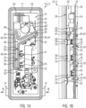
- FIG 1A-B an electric heating device 10 according to the invention is shown with a hold-down device 30.
- the hold-down device 30 is in Figure 1C shown individually.
- the heating device 10 has a heater housing 11 in which a circulation chamber 12 and a connection chamber 20 are arranged next to each other and separated by a partition wall 26.
- the heating device 10 is with a view of the connection chamber 20 and the partition wall 26.
- the circulation chamber 12 with inlet and outlet openings 14 is facing away from the connection chamber 20 and is therefore arranged in the background.
- a circuit board 24 of a control device 22 is arranged in the connection chamber 20, with a hold-down device 30 being arranged on the circuit board 24.
- the partition wall 26 is arranged below the circuit board 24 - into the image plane.
- the partition wall 26 separates the connection chamber 20 from the circulation chamber 12, in which a heat transfer medium W guided through it can be heated by several PTC heating devices 16 that can be controlled by the control device 22.
- the heat transfer medium W can be guided through the circulation chamber 12 via the inlet and outlet openings 14.
- the hold-down device 30 is arranged in the foreground, namely on the side of the circuit board 24 facing away from the partition wall 26.
- the hold-down device 30 has a channel 40 which is divided into three sections 41, 42, 43.
- the three sections 41, 42, 43 are arranged in a Y-shape or star shape to one another and each run at least substantially straight.
- a first section 41 runs along the circuit board 24 above three power transistors 25 of the control device 22.
- two through openings 32 for pins 33 are arranged.
- a second section 42 runs obliquely to the first section 41. Adjacent to the second section 42 is a roof surface indicated with reference number 60', also called a further roof surface 60', which covers a part of the circuit board 24 to keep out liquid F. This (further) roof surface 60' also has a through opening 32.
- a third section 43 of the channel 40 makes the hold-down device 30 Y-shaped or star-shaped because the third section 43 in the interface 46 of the first and second sections 41, 42 borders on the interface 46.
- the third section 43 is also arranged obliquely to the first section 41. All sections 41, 42, 43 lie in one plane.
- the sectional view of the Figure 1B shows that the hold-down device 30 interacts with the control device 22.
- the hold-down device 30 is intended to rest at least indirectly on the circuit board 24 and in particular to press against the circuit board 24.
- a wall 28 or a cover rests on the hold-down device 30, which closes the connection chamber 20.
- the wall 28 exerts a force on the hold-down device 30 in the direction of the control device 22.
- the force is transmitted to the power transistors 25 via elastic elements 34, so that the power transistors 25 are pressed in the direction of the partition wall 26 in order to rest there in a heat-conducting manner, in particular so that the power transistors 25 are cooled by heat dissipation to the partition wall 26.
- the pins 33 protrude from the partition wall 26 in the direction of the connection chamber 20.
- the circuit board 24 is plugged onto the pins 33, and the hold-down device 30 with its through-openings 32 is also plugged onto it. In this way, the hold-down device 30 is centered relative to the circuit board 24 and in particular centered relative to the wall 28.
- the wall 28 does not have to be completely fluid-tight against the hold-down device 30 so that, particularly in the area of the interface 46, moisture F can enter the channel 44 in liquid form or can leave the channel 44 at a lower point, for example an output area 52.
- the wall 28 has an embossing 29 which corresponds to a shoulder 36 of the hold-down device 30, i.e. at least in sections it rests positively against the shoulder 36. This can ensure both a certain sealing of the channel 44 and a material-friendly, larger-area contact of the wall 28 with the hold-down device 30.
- FIG 1C shows the individual hold-down device 30 from Figure 1A-B
- the hold-down device 30 is aligned with the first section 41 pointing downwards, so that a receiving area 48 for incoming moisture F is formed between the second and third sections 42, 43.
- the moisture F which then remains in the funnel-shaped gap at reference number 48 due to the downward force of gravity, can gradually penetrate laterally into the groove 40 or the channel 44 typically formed with the wall 28. However, this does not necessarily have to happen this way. For example, the moisture F can also remain in the receiving area 48 until it evaporates.
- the shoulder 36 runs around all sections 41, 42, 43 or the entire channel 40. In conjunction with the wall 28, the shoulder 36 provides a further channel in which moisture F can be retained, particularly in the receiving area 48.
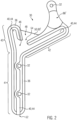
- Figure 2 shows another hold-down device 30 of an electric heating device 10.
- the hold-down device 30 of the Figure 2 modified in such a way that the receiving area 48 has a baffle wall 50, which also acts as a (further) roof surface 60'.
- the baffle wall 50 forms a gap between the wall 28.
- the hold-down device 30 of the Figure 2 in this regard modified in that an opening 54 is provided at the receiving area 48 so that the moisture F can penetrate into the channel 40, in particular from the side, with as little resistance as possible.
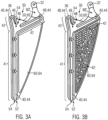
- Figure 3A-B show a further hold-down device 30 of an electric heating device, which, compared to the previously described hold-down device 30 of the Figure 2 has been further modified.
- the hold-down device 30 has an enlarged, extended first section 41, in particular the first section 41 is at least twice as long as the second section 42.
- the hold-down device 30 is also Y-shaped or star-shaped.
- the first section 41 now has three through-openings 32, which are bypassed by the channel 40.
- the output area 52 is provided with an opening 54, so that the moisture F can pass through the opening 54 with as little resistance as possible.
- the hold-down device 30 of the Figure 3A-B opposite the hold-down device 30 of the Figure 2 modified in that - in addition to the (further) roof surface 60' - a particularly approximately triangular roof surface 60 is provided between the first section 41 and the second section 42.
- the roof surface 60 and the recess 64 border on the first section 41 and the second section 42 of the gutter 40.
- the roof surface 60 has the recess 64, whereby the recess 64 points out of the image plane towards the viewer.
- this recess 64 when the hold-down device 30 is installed in a heater housing 11, is oriented away from the partition wall 26, the control device 22 and the circuit board 24. Liquid moisture F can thus collect in it if necessary.
- a drying agent 62 in the recess 64 and to fix it in place thanks to the recess 64.
- a hygroscopic drying agent 62 is added.
- the drying agent 62 is introduced into the recess 64.
- the drying agent 62 can then be held or fixed in the recess by the wall 28 covering the recess 64.
- a narrow circumferential gap between the wall 28 and the edge of the recess 64 can then be sufficient so that the drying agent can absorb moisture F from the air contained in the connection chamber 20.
- the roof surface 60 can also serve to keep moisture F away from the control device 22 by absorbing the air humidity.
Landscapes
- Engineering & Computer Science (AREA)
- General Engineering & Computer Science (AREA)
- Mechanical Engineering (AREA)
- Chemical & Material Sciences (AREA)
- Thermal Sciences (AREA)
- Combustion & Propulsion (AREA)
- Physics & Mathematics (AREA)
- Health & Medical Sciences (AREA)
- Life Sciences & Earth Sciences (AREA)
- Molecular Biology (AREA)
- Drying Of Solid Materials (AREA)
- Electric Stoves And Ranges (AREA)
- Cooling Or The Like Of Electrical Apparatus (AREA)
Applications Claiming Priority (1)
| Application Number | Priority Date | Filing Date | Title |
|---|---|---|---|
| DE102022128348.8A DE102022128348A1 (de) | 2022-10-26 | 2022-10-26 | Elektrische Heizvorrichtung mit einem Niederhalter |
Publications (2)
| Publication Number | Publication Date |
|---|---|
| EP4362607A2 true EP4362607A2 (fr) | 2024-05-01 |
| EP4362607A3 EP4362607A3 (fr) | 2024-05-15 |
Family
ID=88511293
Family Applications (1)
| Application Number | Title | Priority Date | Filing Date |
|---|---|---|---|
| EP23205382.7A Pending EP4362607A3 (fr) | 2022-10-26 | 2023-10-24 | Dispositif de chauffage électrique avec un serre-flan |
Country Status (4)
| Country | Link |
|---|---|
| US (1) | US20240142137A1 (fr) |
| EP (1) | EP4362607A3 (fr) |
| CN (1) | CN117928104A (fr) |
| DE (1) | DE102022128348A1 (fr) |
Cited By (1)
| Publication number | Priority date | Publication date | Assignee | Title |
|---|---|---|---|---|
| FR3162025A1 (fr) * | 2024-05-07 | 2025-11-14 | Valeo Systemes Thermiques | Dispositif de chauffage de fluide, notamment destiné à un véhicule |
Citations (1)
| Publication number | Priority date | Publication date | Assignee | Title |
|---|---|---|---|---|
| EP2466989A1 (fr) | 2010-10-08 | 2012-06-20 | Eberspächer catem GmbH & Co. KG | Procédé de fabrication d'un dispositif de chauffage électrique |
Family Cites Families (6)
| Publication number | Priority date | Publication date | Assignee | Title |
|---|---|---|---|---|
| EP2607121B2 (fr) * | 2011-12-22 | 2020-07-08 | Eberspächer catem GmbH & Co. KG | Dispositif de chauffage électrique, en particulier pour un véhicule automobile |
| DE102017221490A1 (de) * | 2017-11-30 | 2019-06-06 | Eberspächer Catem Gmbh & Co. Kg | Elektrische Heizvorrichtung |
| KR20210066242A (ko) * | 2019-11-28 | 2021-06-07 | 대우전자부품(주) | 면상 발열히터 pcb용 브라켓 |
| DE102020202453B4 (de) * | 2020-02-26 | 2022-09-29 | Eberspächer Catem Gmbh & Co. Kg | Elektrische Heizvorrichtung und Verfahren zu deren Herstellung |
| DE102020207712A1 (de) * | 2020-06-22 | 2021-12-23 | Eberspächer Catem Gmbh & Co. Kg | Steuervorrichtung |
| DE102022123572A1 (de) * | 2022-09-15 | 2024-03-21 | Eberspächer Catem Gmbh & Co. Kg | Steuervorrichtung und elektrische Heizvorrichtung umfassend eine solche |
-
2022
- 2022-10-26 DE DE102022128348.8A patent/DE102022128348A1/de active Pending
-
2023
- 2023-10-24 EP EP23205382.7A patent/EP4362607A3/fr active Pending
- 2023-10-25 CN CN202311399233.9A patent/CN117928104A/zh active Pending
- 2023-10-26 US US18/384,111 patent/US20240142137A1/en active Pending
Patent Citations (1)
| Publication number | Priority date | Publication date | Assignee | Title |
|---|---|---|---|---|
| EP2466989A1 (fr) | 2010-10-08 | 2012-06-20 | Eberspächer catem GmbH & Co. KG | Procédé de fabrication d'un dispositif de chauffage électrique |
Cited By (1)
| Publication number | Priority date | Publication date | Assignee | Title |
|---|---|---|---|---|
| FR3162025A1 (fr) * | 2024-05-07 | 2025-11-14 | Valeo Systemes Thermiques | Dispositif de chauffage de fluide, notamment destiné à un véhicule |
Also Published As
| Publication number | Publication date |
|---|---|
| EP4362607A3 (fr) | 2024-05-15 |
| CN117928104A (zh) | 2024-04-26 |
| DE102022128348A1 (de) | 2024-05-02 |
| US20240142137A1 (en) | 2024-05-02 |
Similar Documents
| Publication | Publication Date | Title |
|---|---|---|
| EP2607121B1 (fr) | Dispositif de chauffage électrique, en particulier pour un véhicule automobile | |
| EP3079442B1 (fr) | Dispositif de chauffage électrique et cadre associé | |
| DE102013205640B4 (de) | Batterieuntereinheit mit mehreren miteinander parallel und/oder seriell verschaltetenBatteriemodulen und Batteriesystem | |
| DE102017128529A1 (de) | Kraftfahrzeugbatterie | |
| WO1996038699A1 (fr) | Echangeur de chaleur | |
| DE102020207966A1 (de) | Kühlanordnung für elektronische Komponenten eines Kraftfahrzeugs | |
| DE102017202768A1 (de) | Energiespeicheranordnung und Kraftfahrzeug | |
| DE102009038978A1 (de) | Vorrichtung zum Erwärmen von Flüssigkeiten | |
| EP2607808A1 (fr) | Elément générateur de chaleur | |
| EP2608633A1 (fr) | Elément générateur de chaleur | |
| DE102019201986A1 (de) | Batteriegehäuse zur Aufnahme wenigstens eines Zellmoduls einer Traktionsbatterie | |
| DE19716401C2 (de) | Kühlanordnung für Elektronikbaugruppen | |
| EP1724536A2 (fr) | Echangeur de chaleur avec partie accumulatrice | |
| EP4362607A2 (fr) | Dispositif de chauffage électrique avec un serre-flan | |
| DE102016217745A1 (de) | Energiespeichereinrichtung | |
| DE102019127230B4 (de) | Kondenswasser-Ableiteinrichtung für ein Batteriemodul sowie Batteriemodul | |
| DE202016006515U1 (de) | Akkublock aus einer Vielzahl von Akkuzellen | |
| DE4225723A1 (de) | Leistungswiderstand für Flüssigkeitskühlung | |
| DE102016125338B4 (de) | System zum Kühlen eines für elektrische Bauteile vorgesehenen Trägersubstrats und Trägersubstrat | |
| DE102019120498A1 (de) | Energiespeichersystem | |
| DE102022116921A1 (de) | Bauteil einer elektrischen Heizvorrichtung und elektrische Heizvorrichtung | |
| DE102016106180A1 (de) | Kühlvorrichtung für die Kühlung wenigstens einer elektrischen Komponente eines Fahrzeugs | |
| DE102019211565B4 (de) | Elektrische Heizvorrichtung und Verfahren zu deren Herstellung | |
| DE102005026703A1 (de) | Gehäuse für elektrische Bauelemente | |
| DE102017212209B4 (de) | Energiespeicheranordnung |
Legal Events
| Date | Code | Title | Description |
|---|---|---|---|
| PUAI | Public reference made under article 153(3) epc to a published international application that has entered the european phase |
Free format text: ORIGINAL CODE: 0009012 |
|
| STAA | Information on the status of an ep patent application or granted ep patent |
Free format text: STATUS: THE APPLICATION HAS BEEN PUBLISHED |
|
| PUAL | Search report despatched |
Free format text: ORIGINAL CODE: 0009013 |
|
| AK | Designated contracting states |
Kind code of ref document: A2 Designated state(s): AL AT BE BG CH CY CZ DE DK EE ES FI FR GB GR HR HU IE IS IT LI LT LU LV MC ME MK MT NL NO PL PT RO RS SE SI SK SM TR |
|
| AK | Designated contracting states |
Kind code of ref document: A3 Designated state(s): AL AT BE BG CH CY CZ DE DK EE ES FI FR GB GR HR HU IE IS IT LI LT LU LV MC ME MK MT NL NO PL PT RO RS SE SI SK SM TR |
|
| RIC1 | Information provided on ipc code assigned before grant |
Ipc: F24H 3/04 20220101ALI20240405BHEP Ipc: F24H 9/20 20220101ALI20240405BHEP Ipc: B60H 1/22 20060101ALI20240405BHEP Ipc: H05B 3/24 20060101AFI20240405BHEP |
|
| STAA | Information on the status of an ep patent application or granted ep patent |
Free format text: STATUS: REQUEST FOR EXAMINATION WAS MADE |
|
| 17P | Request for examination filed |
Effective date: 20240705 |
|
| RBV | Designated contracting states (corrected) |
Designated state(s): AL AT BE BG CH CY CZ DE DK EE ES FI FR GB GR HR HU IE IS IT LI LT LU LV MC ME MK MT NL NO PL PT RO RS SE SI SK SM TR |