EP4364584A1 - Plateau destiné à recevoir des articles en forme de tige de l'industrie du tabac - Google Patents
Plateau destiné à recevoir des articles en forme de tige de l'industrie du tabac Download PDFInfo
- Publication number
- EP4364584A1 EP4364584A1 EP23205465.0A EP23205465A EP4364584A1 EP 4364584 A1 EP4364584 A1 EP 4364584A1 EP 23205465 A EP23205465 A EP 23205465A EP 4364584 A1 EP4364584 A1 EP 4364584A1
- Authority
- EP
- European Patent Office
- Prior art keywords
- tray
- receiving part
- base part
- receiving
- bottom wall
- Prior art date
- Legal status (The legal status is an assumption and is not a legal conclusion. Google has not performed a legal analysis and makes no representation as to the accuracy of the status listed.)
- Granted
Links
Images


Classifications
-
- A—HUMAN NECESSITIES
- A24—TOBACCO; CIGARS; CIGARETTES; SIMULATED SMOKING DEVICES; SMOKERS' REQUISITES
- A24C—MACHINES FOR MAKING CIGARS OR CIGARETTES
- A24C5/00—Making cigarettes; Making tipping materials for, or attaching filters or mouthpieces to, cigars or cigarettes
- A24C5/35—Adaptations of conveying apparatus for transporting cigarettes from making machine to packaging machine
- A24C5/352—Adaptations of conveying apparatus for transporting cigarettes from making machine to packaging machine using containers, i.e. boats
- A24C5/358—Boat constructions
-
- A—HUMAN NECESSITIES
- A24—TOBACCO; CIGARS; CIGARETTES; SIMULATED SMOKING DEVICES; SMOKERS' REQUISITES
- A24C—MACHINES FOR MAKING CIGARS OR CIGARETTES
- A24C5/00—Making cigarettes; Making tipping materials for, or attaching filters or mouthpieces to, cigars or cigarettes
- A24C5/35—Adaptations of conveying apparatus for transporting cigarettes from making machine to packaging machine
- A24C5/352—Adaptations of conveying apparatus for transporting cigarettes from making machine to packaging machine using containers, i.e. boats
Definitions
- the invention relates to a tray for receiving rod-shaped articles of the tobacco processing industry, comprising a tray body formed by a rear wall, two side walls which are at least substantially parallel and spaced apart from one another, and a base wall, forming a receiving space for the rod-shaped articles which is open at the front and at the top, wherein the receiving space is divided by a partition wall extending from side wall to side wall.
- Such trays are used in the tobacco processing industry.
- the rod-shaped articles for example tobacco sticks, cigarettes, filters, filter rods and filter rod segments or the like, are transported and/or stored in containers, the so-called trays.
- the trays can be designed as trays with a single receiving space for all articles or as shaft trays in which the articles are located in several separate shafts aligned perpendicular to the base wall.
- the rod-shaped articles are filled into the trays for storage - preferably as an intermediate product - using a tray filling device.
- the stored articles are delivered to downstream machines, such as packaging machines or production machines, using a tray emptying device or are introduced into an existing mass flow.
- standard trays with external dimensions of, for example, approx. 720 mm width ⁇ 400 mm height ⁇ 125 mm depth (W ⁇ H ⁇ D) are used.
- the receiving space which is undivided in height, is completely available for filling with rod-shaped articles.
- the load on the articles As the filling height of the trays increases, the load on the articles further down also increases. In the case of sensitive products or intermediate products, the load due to the weight of the articles is too great for the articles below, which can cause damage to the articles.
- a partial filling of the receiving space in the Standard trays should be considered.
- emptying the partially filled standard trays is problematic, as the items fly around in a disorganized manner when emptied, thus preventing orderly and controlled further processing.
- partial trays are used that have a reduced storage space.
- the items are filled into this storage space, which is reduced in height and therefore in volume, using suitable devices, known as tray fillers.
- suitable devices known as tray fillers.
- the smaller number of items - due to the reduced height - reduces the load on the items at the bottom.
- Filling such partial batches i.e. trays with smaller external dimensions than the standard trays mentioned, is possible with the known tray fillers and with little adjustment effort.
- emptying the partial trays is problematic and involves considerable adjustment effort, as the known emptying devices, known as tray emptyers, have to be adapted to the changed geometry and the changed external dimensions of the partial trays.
- tray emptyers To avoid this effort, trays are known as standard trays, which have a storage space divided in height, whereby only the upper part of the storage space of the tray is filled with items.
- a generic (standard) tray with a storage space divided in height is known.
- the partition wall which divides the storage space in height into an upper storage space and a lower empty space, is adjustably attached along the side walls of the tray body so that the size of the storage space is variable.
- the size/height of the storage space is reduced in order to reduce the load on the items below.
- the storage space can be enlarged. Due to the consistent external geometry and the constant external dimensions of the standard trays, both filling and emptying can be carried out using the known devices without adjustment to the devices.
- the known tray body is designed in one piece, the entire tray must always be handled even with a reduced filling.
- the invention is therefore based on the object of creating a simple and space-optimized shelf that is universally applicable and easy to handle.
- a tray with the features mentioned at the beginning in that the tray body is designed to be divisible.
- the divisibility of the tray body ensures alternating operation with complete (standard) trays and partial trays. Only the parts of the tray that are absolutely necessary for filling and emptying need to be handled.
- the two parts together form a standard tray, i.e. a tray that is adapted in terms of geometry and external dimensions to the known devices for filling and in particular emptying. Only part of the tray can and must be handled for filling.
- the upper part of the divisible tray can be detached from the lower part of the tray for filling. Before emptying, the two parts of the tray can be put back together in order to have the geometry required by the emptying device and the external dimensions of a standard tray for emptying.
- a preferred embodiment of the tray is characterized in that the tray body is formed from two components that are detachably connected to one another, namely a base part and a receiving part, whereby both the base part and the receiving part have rear wall sections and side wall sections of the tray body, and whereby the bottom wall of the tray body is formed by a bottom wall of the base part and the partition wall is formed by a bottom wall of the receiving part.
- the base part and the receiving part form a standard tray that is conventional in terms of geometry and external dimensions and has a receiving space that is divided in height.
- the base part with an empty space can remain in the area of a tray emptyer, while the receiving part with a storage space can be filled manually or automatically in a tray filler.
- the receiving part has a reduced height compared to a standard tray, preferably half the filling height of a standard tray, the weight of the lowest layer of articles is reduced, even when the receiving part is completely full. Only the receiving part has to be handled for filling. Before emptying, the receiving part is placed on the base part, so that the entire tray is then handled as a standard tray. With the tray according to the invention, a Automated emptying is guaranteed without any significant adjustments to the tray emptyers set to standard trays.
- a fastening means is provided for detachably connecting the base part and the receiving part.
- the fastening means is preferably designed and configured for connecting the base part and the receiving part without the need for any tools.
- the fastening means enables the base part and the receiving part to be connected and released quickly and easily, e.g. by means of a combined plug-in and snap-in connection.
- the base part and the receiving part are essentially identical in construction, in particular with regard to the geometry and the external dimensions of the rear wall sections, side wall sections and bottom walls.
- both the base part and the receiving part have the geometry and the external dimensions of half a standard tray.
- the existing differences, in particular the fastening means on the base part and the corresponding adjustments of the receiving part to the fastening means have no effect on the external dimensions and thus ensure safe handling of the receiving part alone and in an assembled state with the base part by the tray fillers and tray emptyers.
- the base part and the receiving part can also have different external dimensions, for example in a 1/3 to 2/3 division. In other words, for example, the base part is 1/3 the size of the standard tray, while the receiving part is 2/3 the size of the standard tray. Other size ratios are also possible.
- the fastening means comprises two holding elements which are arranged on the opposite side wall sections of the base part. Arranged on the inside of the side wall sections of the base part, the holding elements do not impair the handling of the trays in the assembled state and also ensure a stable connection between the base part and the receiving part.
- the number and positioning of the holding means can vary.
- Each holding element is advantageously designed and configured to produce a positive and/or non-positive connection with the receiving part.
- Different means can be used as fastening means or holding elements.
- a predominantly non-positive connection can be created, for example, using magnets or clamping fasteners.
- a predominantly positive connection can be created, for example, using a type of spring/groove connection with a positively engaging locking bracket.
- a fastening means can also be used that is designed and configured for a combined positive and non-positive connection, e.g. in the form of a (quick) snap fastener using a spring plate that engages in recesses.
- the holding elements are conveniently attached to the base part in a detachable manner. This means that the base part can ultimately also be used as a receiving part or partial tray when the holding elements are removed, which improves universal use and handling.
- each holding element has at least one projection that protrudes beyond the side wall sections of the base part.
- the number of projections can vary.
- each holding element has two projections that protrude beyond the side wall sections of the base part and are designed and configured to produce a positive connection with the receiving part.
- two pins or the like are provided on the side facing upwards in the direction of the receiving part to be combined, which are designed and configured to engage in corresponding recesses in the bottom wall of the receiving part. The pins create a positive connection between the two parts, by means of which the two parts can be positioned and aligned with respect to one another.
- each holding element has at least one magnet, which is positioned on the holding element on the side facing the bottom wall of the receiving part.
- the number of magnets can vary.
- each holding element has two magnets, which are positioned on the holding element on the side facing the bottom wall of the receiving part, wherein the magnets are designed and arranged to produce a force-fitting connection with the receiving part. Due to the force-fitting connection of the base part on the one hand and the receiving part On the other hand, by means of the magnets, especially in combination with the positive connection using the pins, a secure and stable connection is achieved, which can, however, be easily released and reconnected manually and without any tools.
- the receiving part has a recess in its bottom wall on the side facing the base part, corresponding to each projection, for receiving the projection of the holding elements. It is also advantageous for the receiving part to have a magnetic element in its bottom wall on the side facing the base part, corresponding to each magnet of the base part. This design ensures that the connection between the base part and the receiving part can be made and released quickly and safely.
- a counter wedge is arranged on the bottom wall of the receiving part on the side facing away from the base part.
- a counter wedge is particularly preferred when the trays are used in connection with filters as rod-shaped articles and also serves to cover screws or other fastening means which are arranged, for example, for fastening the magnetic elements in the area of the bottom wall of the receiving part.
- the counter wedge is detachably connected to the base wall of the receiving part. This means that the receiving part can be used universally.
- the tray shown is used in the tobacco processing industry to transport and store rod-shaped articles such as filters, cigarettes, multi-segment filter sections or the like.
- the tray can have a single receiving space extending over the entire width of the tray for storing articles or, in the example of a shaft tray, several shaft-shaped receiving spaces formed by partition walls aligned vertically to the base wall.
- a tray 10 which is designed and equipped to accommodate rod-shaped articles from the tobacco processing industry.
- the tray 10 comprises a tray body 15 formed by a rear wall 11, two side walls 12, 13 which are at least substantially parallel and spaced apart from one another, and a base wall 14, forming a receiving space 16 for the rod-shaped articles which is open at the front and at the top, the receiving space 16 being divided by a partition wall 17 extending from side wall 12 to side wall 13.
- the division of the receiving space 16 creates, on the one hand, a storage space 18 for the articles, and on the other hand, an empty space 19.
- the storage space 18 is divided into several shafts by partition walls aligned vertically to the partition wall 17.
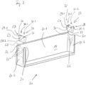
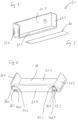
- This tray 10 is characterized according to the invention in that the tray body 15 is designed to be divisible. While in the Figure 1 the tray 10 is shown in the assembled state of the tray body 15, the Figure 2 the tray 10 with a split tray body 15. The two parts of the tray body 15 can be handled independently of each other.
- a so-called standard tray is shown as tray 10 with regard to its external dimensions, with a storage space 18 as the receiving space 16 that is common to all rod-shaped articles.
- the invention with all embodiments is also applicable in the same way to a shaft tray in which the storage space 18 as the receiving space 16 is divided into individual shafts by partitions that can be firmly or detachably connected to the tray body 15.
- the tray 10 has the usual external dimensions of approximately 720 mm wide x 400 mm high x 125 mm deep (W ⁇ H ⁇ D). These dimensions are tailored to the devices for filling and emptying the trays 10.
- the trays 10 can also have other dimensions with regard to their external dimensions, corresponding and adapted to the respective devices for filling and emptying the trays 10.
- the tray 10 or the tray body 15, which is preferably made at least partially from an electrically conductive plastic, is formed from two components that are detachably connected to one another, namely a base part 20 and a receiving part 21, wherein both the base part 20 and the receiving part 21 have rear wall sections 20.1, 21.1 and side wall sections 20.2, 20.3; 21.2, 21.3 of the tray body 15, and wherein the bottom wall 14 of the tray body 15 is formed by a bottom wall 20.4 of the base part 20 and the partition wall 17 is formed by a bottom wall 21.4 of the receiving part 21.
- the side wall 12 is therefore formed from the side wall sections 20.2, 21.2.
- the side wall 13 is formed from the side wall sections 20.3, 21.3.
- the tray is shown in assembled condition, i.e. especially for automatic emptying.
- the tray 10 is shown in a split state, in particular for filling the receiving part 21 independently and detached from the base part 20.
- the connection between the base part 20 and the receiving part 21 is realized with a fastening means 22 for detachably connecting the base part 20 and the receiving part 21.
- the base part 20 and the receiving part 21 are essentially identical in construction, in particular with regard to the geometry and the external dimensions of rear wall sections 20.1, 21.1, side wall sections 20.2, 20.3; 21.2, 21.3 and bottom walls 20.4, 21.4.
- the fastening means 22 is assigned to the base part 20.
- the fastening means 22 in the embodiment shown comprises two holding elements 23, 24 which are arranged on the opposite side wall sections 20.2, 20.3 of the base part 20.
- each holding element 23, 24 is designed and configured to produce a positive and non-positive connection with the receiving part 21.
- Each holding element 23, 24, made e.g. from a plastic or preferably from aluminum, is detachably attached to the base part 20.
- four screws 25, 26 are provided, by means of which the holding element 23, 24 is connected to the respective side wall section 20.2, 20.3.
- each holding element 23, 24 has at least one projection 27, 28 that protrudes beyond the side wall sections 20.2, 20.3 of the base part 20.
- each holding element 23, 24 has two projections 27.1, 27.2; 28.1, 28.2 that protrude beyond the side wall sections 20.2, 20.3 of the base part 20 and are designed and configured to produce the positive connection with the receiving part 21.
- the side wall sections 20.2, 20.3 have a recess 32, 33 on their upwardly directed edge 30, 31, into which or on which the holding elements 23, 24 are placed.
- each holding element 23, 24 has at least one magnet 34, 35, which is positioned on the holding element 23, 24 on the side facing the bottom wall 21.4 of the receiving part 21.
- each holding element 23, 24 has two magnets 34.1, 34.2; 35.1, 35.2, which are positioned on the holding element 23, 24 on the side facing the bottom wall 21.4 of the receiving part 21.
- the magnets 34.1, 34.2; 35.1, 35.2 are embedded in recesses 36, 37 of the holding elements 23, 24 and are designed and configured to produce a force-fit connection with the receiving part 21.
- the receiving part 21 has a recess 38.1, 38.2; 39.1, 39.2 in its bottom wall 21.4 on the side facing the base part 20, corresponding to each projection 27.1, 27.2; 28.1, 28.2, for receiving the projections 27.1, 27.2; 28.1, 28.2 of the holding elements 23, 24.
- the receiving part 21 has a magnetic element 40.1, 40.2; 41.1, 41.2 in its bottom wall 21.4 on the side facing the base part 20, corresponding to each magnet 34.1, 34.2; 35.1, 35.2 of the base part 20.
- the magnetic elements 40.1, 40.2; 41.1, 41.2 can be inserted or plugged into recesses in the base wall 21.4.
- the magnetic elements 40.1, 40.2; 41.1, 41.2 can also be screwed in.
- the base walls 20.4 and/or 21.4 can be flat.
- the base walls 20.4 and/or 21.4 can also be inclined, such that the base walls 20.4 and/or 21.4 are designed to slope towards the respective rear wall section 20.1, 21.1.
- a counter wedge 42 it can be useful or necessary for a counter wedge 42 to be arranged, in particular on the base wall 21.4 of the receiving part 21 on the side facing away from the base part 20.
- the inclination of the base wall 21.4 can be changed using the counter wedge 42. If the base wall 21.4 itself is flat, the counter wedge 42 creates an inclined support surface of the base wall 21.4 for the articles, which slopes towards the rear wall section 21.1.
- the counter wedge 42 can be used to compensate for this, so that the support surface on which the articles rest is then flat.
- the counter wedge 42 can be inserted loosely.
- the counter wedge 42 is preferably detachably connected to the base wall of the receiving part. The orientation in which the counter wedge 42 is inserted varies depending on whether a flat support surface or an inclined support surface is to be achieved.
Landscapes
- Details Of Rigid Or Semi-Rigid Containers (AREA)
- Supports Or Holders For Household Use (AREA)
Applications Claiming Priority (1)
| Application Number | Priority Date | Filing Date | Title |
|---|---|---|---|
| DE102022128888.9A DE102022128888A1 (de) | 2022-11-01 | 2022-11-01 | Schragen zur Aufnahme stabförmiger Artikel der tabakverarbeitenden Industrie |
Publications (2)
| Publication Number | Publication Date |
|---|---|
| EP4364584A1 true EP4364584A1 (fr) | 2024-05-08 |
| EP4364584B1 EP4364584B1 (fr) | 2025-09-10 |
Family
ID=88510874
Family Applications (1)
| Application Number | Title | Priority Date | Filing Date |
|---|---|---|---|
| EP23205465.0A Active EP4364584B1 (fr) | 2022-11-01 | 2023-10-24 | Bateau pour recevoir des articles en forme de tige de l'industrie de transformation du tabac |
Country Status (4)
| Country | Link |
|---|---|
| EP (1) | EP4364584B1 (fr) |
| CN (1) | CN117981899A (fr) |
| DE (1) | DE102022128888A1 (fr) |
| PL (1) | PL4364584T3 (fr) |
Families Citing this family (1)
| Publication number | Priority date | Publication date | Assignee | Title |
|---|---|---|---|---|
| EP4652861A1 (fr) * | 2024-05-23 | 2025-11-26 | International Tobacco Machinery Poland Sp. z o.o. | Système et appareil de l'industrie du tabac, et élément de conversion et couvercle |
Citations (1)
| Publication number | Priority date | Publication date | Assignee | Title |
|---|---|---|---|---|
| WO2014209842A1 (fr) | 2013-06-28 | 2014-12-31 | Celanese Acetate Llc | Bacs d'alimentation modifiés de tiges de filtre pour masses poreuses |
-
2022
- 2022-11-01 DE DE102022128888.9A patent/DE102022128888A1/de active Pending
-
2023
- 2023-10-24 PL PL23205465.0T patent/PL4364584T3/pl unknown
- 2023-10-24 EP EP23205465.0A patent/EP4364584B1/fr active Active
- 2023-10-31 CN CN202311432896.6A patent/CN117981899A/zh active Pending
Patent Citations (1)
| Publication number | Priority date | Publication date | Assignee | Title |
|---|---|---|---|---|
| WO2014209842A1 (fr) | 2013-06-28 | 2014-12-31 | Celanese Acetate Llc | Bacs d'alimentation modifiés de tiges de filtre pour masses poreuses |
Also Published As
| Publication number | Publication date |
|---|---|
| DE102022128888A1 (de) | 2024-05-02 |
| CN117981899A (zh) | 2024-05-07 |
| PL4364584T3 (pl) | 2026-01-26 |
| EP4364584B1 (fr) | 2025-09-10 |
Similar Documents
| Publication | Publication Date | Title |
|---|---|---|
| EP1922954B1 (fr) | Dispositif de dépôt et de tri | |
| DE2916769A1 (de) | Vorrichtung zur halterung und lagerung von bestueckten printplatten o.ae. teilen | |
| EP0411391A1 (fr) | Palette de transport | |
| DE2207914C3 (de) | Vorrichtung zum Einsetzen elektrischer Bauteile | |
| DE102008064366A1 (de) | Großladungsträger | |
| EP4364584B1 (fr) | Bateau pour recevoir des articles en forme de tige de l'industrie de transformation du tabac | |
| EP3235389B1 (fr) | Récipient destiné à recevoir ou à délivrer des portions d'un article en forme de tige provenant d'un débit massique de produit formé par l'industrie du tabac et système de discrétisation ou de formation d'un débit massique de produit comprenant de tels récipients | |
| DE2619151B2 (de) | Lagereinrichtung für Werkzeuge | |
| DE102013020292B4 (de) | Batteriesystem für ein Flurförderzeug | |
| DE4434286C1 (de) | Verwendung eines plattenförmigen Trägers zur Halterung von einem Stapel Flachdichtungen | |
| EP0365936A2 (fr) | Disposition d'armoire | |
| WO2008062029A1 (fr) | Ensemble d'emballage, procédé et dispositif de fabrication et de remplissage d'emballages | |
| DE19822972A1 (de) | Vorrichtung zum lösbaren Festlegen von Gegenständen | |
| EP0123077A1 (fr) | Récipient d'outillage | |
| EP0634334B1 (fr) | Récipient de stockage avec éléments de guidage | |
| DE102021102195B4 (de) | Rahmen für eine Transport- und Lagereinheit | |
| DE8137602U1 (de) | Stapelbarer ablagebehaelter mit auszugschublade | |
| DE102014016161A1 (de) | Schragen zur Aufnahme stabförmiger Artikel der Tabak verarbeitenden lndustrie sowie Transport- und/oder Speicheranordnung umfassend mindestens zwei Schragen zur Aufnahme stabförmiger Artikel der Tabak verarbeitenden Industrie | |
| DE20210952U1 (de) | Vorrichtung zur Lagerung von Implantaten und/oder Instrumenten im chirurgischen Bereich | |
| EP1080024A1 (fr) | Dispositif pour fournir du materiel a des postes de travail | |
| DE10300625B3 (de) | Vorrichtung und Verfahren zum Beschicken einer Waage mit verschiedenem Wägegut | |
| EP3970985B1 (fr) | Agencement de panier à lettre | |
| DE29511834U1 (de) | Aufbewahrungsbehälter | |
| EP4480839A2 (fr) | Dispositif de transfert, machine d'emballage dotée d'un tel dispositif de transfert et procédé de transfert d'un ou plusieurs produits, en particulier des aliments/n, au moyen d'un tel dispositif de transfert | |
| DE1429886C3 (de) | Paniertablett für verschiedenes, getrennt anzuwendendes Paniergut |
Legal Events
| Date | Code | Title | Description |
|---|---|---|---|
| PUAI | Public reference made under article 153(3) epc to a published international application that has entered the european phase |
Free format text: ORIGINAL CODE: 0009012 |
|
| STAA | Information on the status of an ep patent application or granted ep patent |
Free format text: STATUS: THE APPLICATION HAS BEEN PUBLISHED |
|
| AK | Designated contracting states |
Kind code of ref document: A1 Designated state(s): AL AT BE BG CH CY CZ DE DK EE ES FI FR GB GR HR HU IE IS IT LI LT LU LV MC ME MK MT NL NO PL PT RO RS SE SI SK SM TR |
|
| STAA | Information on the status of an ep patent application or granted ep patent |
Free format text: STATUS: REQUEST FOR EXAMINATION WAS MADE |
|
| 17P | Request for examination filed |
Effective date: 20241029 |
|
| RBV | Designated contracting states (corrected) |
Designated state(s): AL AT BE BG CH CY CZ DE DK EE ES FI FR GB GR HR HU IE IS IT LI LT LU LV MC ME MK MT NL NO PL PT RO RS SE SI SK SM TR |
|
| GRAP | Despatch of communication of intention to grant a patent |
Free format text: ORIGINAL CODE: EPIDOSNIGR1 |
|
| STAA | Information on the status of an ep patent application or granted ep patent |
Free format text: STATUS: GRANT OF PATENT IS INTENDED |
|
| INTG | Intention to grant announced |
Effective date: 20250409 |
|
| GRAS | Grant fee paid |
Free format text: ORIGINAL CODE: EPIDOSNIGR3 |
|
| GRAA | (expected) grant |
Free format text: ORIGINAL CODE: 0009210 |
|
| STAA | Information on the status of an ep patent application or granted ep patent |
Free format text: STATUS: THE PATENT HAS BEEN GRANTED |
|
| AK | Designated contracting states |
Kind code of ref document: B1 Designated state(s): AL AT BE BG CH CY CZ DE DK EE ES FI FR GB GR HR HU IE IS IT LI LT LU LV MC ME MK MT NL NO PL PT RO RS SE SI SK SM TR |
|
| REG | Reference to a national code |
Ref country code: GB Ref legal event code: FG4D Free format text: NOT ENGLISH |
|
| REG | Reference to a national code |
Ref country code: CH Ref legal event code: EP |
|
| REG | Reference to a national code |
Ref country code: DE Ref legal event code: R096 Ref document number: 502023001762 Country of ref document: DE |
|
| REG | Reference to a national code |
Ref country code: IE Ref legal event code: FG4D Free format text: LANGUAGE OF EP DOCUMENT: GERMAN |
|
| REG | Reference to a national code |
Ref country code: NL Ref legal event code: FP |
|
| PGFP | Annual fee paid to national office [announced via postgrant information from national office to epo] |
Ref country code: DE Payment date: 20251030 Year of fee payment: 3 |
|
| PG25 | Lapsed in a contracting state [announced via postgrant information from national office to epo] |
Ref country code: NO Free format text: LAPSE BECAUSE OF FAILURE TO SUBMIT A TRANSLATION OF THE DESCRIPTION OR TO PAY THE FEE WITHIN THE PRESCRIBED TIME-LIMIT Effective date: 20251210 |
|
| REG | Reference to a national code |
Ref country code: LT Ref legal event code: MG9D |
|
| PGFP | Annual fee paid to national office [announced via postgrant information from national office to epo] |
Ref country code: AT Payment date: 20260113 Year of fee payment: 3 |
|
| PG25 | Lapsed in a contracting state [announced via postgrant information from national office to epo] |
Ref country code: FI Free format text: LAPSE BECAUSE OF FAILURE TO SUBMIT A TRANSLATION OF THE DESCRIPTION OR TO PAY THE FEE WITHIN THE PRESCRIBED TIME-LIMIT Effective date: 20250910 |
|
| PGFP | Annual fee paid to national office [announced via postgrant information from national office to epo] |
Ref country code: IT Payment date: 20251031 Year of fee payment: 3 |
|
| PG25 | Lapsed in a contracting state [announced via postgrant information from national office to epo] |
Ref country code: HR Free format text: LAPSE BECAUSE OF FAILURE TO SUBMIT A TRANSLATION OF THE DESCRIPTION OR TO PAY THE FEE WITHIN THE PRESCRIBED TIME-LIMIT Effective date: 20250910 |
|
| PG25 | Lapsed in a contracting state [announced via postgrant information from national office to epo] |
Ref country code: GR Free format text: LAPSE BECAUSE OF FAILURE TO SUBMIT A TRANSLATION OF THE DESCRIPTION OR TO PAY THE FEE WITHIN THE PRESCRIBED TIME-LIMIT Effective date: 20251211 |
|
| PG25 | Lapsed in a contracting state [announced via postgrant information from national office to epo] |
Ref country code: SE Free format text: LAPSE BECAUSE OF FAILURE TO SUBMIT A TRANSLATION OF THE DESCRIPTION OR TO PAY THE FEE WITHIN THE PRESCRIBED TIME-LIMIT Effective date: 20250910 |
|
| PG25 | Lapsed in a contracting state [announced via postgrant information from national office to epo] |
Ref country code: LV Free format text: LAPSE BECAUSE OF FAILURE TO SUBMIT A TRANSLATION OF THE DESCRIPTION OR TO PAY THE FEE WITHIN THE PRESCRIBED TIME-LIMIT Effective date: 20250910 |
|
| PG25 | Lapsed in a contracting state [announced via postgrant information from national office to epo] |
Ref country code: BG Free format text: LAPSE BECAUSE OF FAILURE TO SUBMIT A TRANSLATION OF THE DESCRIPTION OR TO PAY THE FEE WITHIN THE PRESCRIBED TIME-LIMIT Effective date: 20250910 |
|
| PG25 | Lapsed in a contracting state [announced via postgrant information from national office to epo] |
Ref country code: RS Free format text: LAPSE BECAUSE OF FAILURE TO SUBMIT A TRANSLATION OF THE DESCRIPTION OR TO PAY THE FEE WITHIN THE PRESCRIBED TIME-LIMIT Effective date: 20251210 |
|
| PG25 | Lapsed in a contracting state [announced via postgrant information from national office to epo] |
Ref country code: ES Free format text: LAPSE BECAUSE OF FAILURE TO SUBMIT A TRANSLATION OF THE DESCRIPTION OR TO PAY THE FEE WITHIN THE PRESCRIBED TIME-LIMIT Effective date: 20250910 |
|
| PG25 | Lapsed in a contracting state [announced via postgrant information from national office to epo] |
Ref country code: SM Free format text: LAPSE BECAUSE OF FAILURE TO SUBMIT A TRANSLATION OF THE DESCRIPTION OR TO PAY THE FEE WITHIN THE PRESCRIBED TIME-LIMIT Effective date: 20250910 |
|
| PG25 | Lapsed in a contracting state [announced via postgrant information from national office to epo] |
Ref country code: RO Free format text: LAPSE BECAUSE OF FAILURE TO SUBMIT A TRANSLATION OF THE DESCRIPTION OR TO PAY THE FEE WITHIN THE PRESCRIBED TIME-LIMIT Effective date: 20250910 |
|
| PG25 | Lapsed in a contracting state [announced via postgrant information from national office to epo] |
Ref country code: IS Free format text: LAPSE BECAUSE OF FAILURE TO SUBMIT A TRANSLATION OF THE DESCRIPTION OR TO PAY THE FEE WITHIN THE PRESCRIBED TIME-LIMIT Effective date: 20260110 |
|
| PG25 | Lapsed in a contracting state [announced via postgrant information from national office to epo] |
Ref country code: PT Free format text: LAPSE BECAUSE OF FAILURE TO SUBMIT A TRANSLATION OF THE DESCRIPTION OR TO PAY THE FEE WITHIN THE PRESCRIBED TIME-LIMIT Effective date: 20260112 Ref country code: CZ Free format text: LAPSE BECAUSE OF FAILURE TO SUBMIT A TRANSLATION OF THE DESCRIPTION OR TO PAY THE FEE WITHIN THE PRESCRIBED TIME-LIMIT Effective date: 20250910 |
|
| PGFP | Annual fee paid to national office [announced via postgrant information from national office to epo] |
Ref country code: PL Payment date: 20251014 Year of fee payment: 3 |
|
| PG25 | Lapsed in a contracting state [announced via postgrant information from national office to epo] |
Ref country code: EE Free format text: LAPSE BECAUSE OF FAILURE TO SUBMIT A TRANSLATION OF THE DESCRIPTION OR TO PAY THE FEE WITHIN THE PRESCRIBED TIME-LIMIT Effective date: 20250910 Ref country code: SK Free format text: LAPSE BECAUSE OF FAILURE TO SUBMIT A TRANSLATION OF THE DESCRIPTION OR TO PAY THE FEE WITHIN THE PRESCRIBED TIME-LIMIT Effective date: 20250910 |