EP4364703A2 - Entwässerungsvorrichtung - Google Patents
Entwässerungsvorrichtung Download PDFInfo
- Publication number
- EP4364703A2 EP4364703A2 EP24166649.4A EP24166649A EP4364703A2 EP 4364703 A2 EP4364703 A2 EP 4364703A2 EP 24166649 A EP24166649 A EP 24166649A EP 4364703 A2 EP4364703 A2 EP 4364703A2
- Authority
- EP
- European Patent Office
- Prior art keywords
- medical device
- retention member
- proximal
- tubular body
- elongate tubular
- Prior art date
- Legal status (The legal status is an assumption and is not a legal conclusion. Google has not performed a legal analysis and makes no representation as to the accuracy of the status listed.)
- Pending
Links
Images





Classifications
-
- A—HUMAN NECESSITIES
- A61—MEDICAL OR VETERINARY SCIENCE; HYGIENE
- A61F—FILTERS IMPLANTABLE INTO BLOOD VESSELS; PROSTHESES; DEVICES PROVIDING PATENCY TO, OR PREVENTING COLLAPSING OF, TUBULAR STRUCTURES OF THE BODY, e.g. STENTS; ORTHOPAEDIC, NURSING OR CONTRACEPTIVE DEVICES; FOMENTATION; TREATMENT OR PROTECTION OF EYES OR EARS; BANDAGES, DRESSINGS OR ABSORBENT PADS; FIRST-AID KITS
- A61F2/00—Filters implantable into blood vessels; Prostheses, i.e. artificial substitutes or replacements for parts of the body; Appliances for connecting them with the body; Devices providing patency to, or preventing collapsing of, tubular structures of the body, e.g. stents
- A61F2/82—Devices providing patency to, or preventing collapsing of, tubular structures of the body, e.g. stents
- A61F2/86—Stents in a form characterised by the wire-like elements; Stents in the form characterised by a net-like or mesh-like structure
- A61F2/90—Stents in a form characterised by the wire-like elements; Stents in the form characterised by a net-like or mesh-like structure characterised by a net-like or mesh-like structure
-
- A—HUMAN NECESSITIES
- A61—MEDICAL OR VETERINARY SCIENCE; HYGIENE
- A61B—DIAGNOSIS; SURGERY; IDENTIFICATION
- A61B17/00—Surgical instruments, devices or methods
- A61B17/11—Surgical instruments, devices or methods for performing anastomosis; Buttons for anastomosis
- A61B17/1114—Surgical instruments, devices or methods for performing anastomosis; Buttons for anastomosis of the digestive tract, e.g. bowels or oesophagus
-
- A—HUMAN NECESSITIES
- A61—MEDICAL OR VETERINARY SCIENCE; HYGIENE
- A61F—FILTERS IMPLANTABLE INTO BLOOD VESSELS; PROSTHESES; DEVICES PROVIDING PATENCY TO, OR PREVENTING COLLAPSING OF, TUBULAR STRUCTURES OF THE BODY, e.g. STENTS; ORTHOPAEDIC, NURSING OR CONTRACEPTIVE DEVICES; FOMENTATION; TREATMENT OR PROTECTION OF EYES OR EARS; BANDAGES, DRESSINGS OR ABSORBENT PADS; FIRST-AID KITS
- A61F2/00—Filters implantable into blood vessels; Prostheses, i.e. artificial substitutes or replacements for parts of the body; Appliances for connecting them with the body; Devices providing patency to, or preventing collapsing of, tubular structures of the body, e.g. stents
- A61F2/02—Prostheses implantable into the body
- A61F2/04—Hollow or tubular parts of organs, e.g. bladders, tracheae, bronchi or bile ducts
-
- A—HUMAN NECESSITIES
- A61—MEDICAL OR VETERINARY SCIENCE; HYGIENE
- A61F—FILTERS IMPLANTABLE INTO BLOOD VESSELS; PROSTHESES; DEVICES PROVIDING PATENCY TO, OR PREVENTING COLLAPSING OF, TUBULAR STRUCTURES OF THE BODY, e.g. STENTS; ORTHOPAEDIC, NURSING OR CONTRACEPTIVE DEVICES; FOMENTATION; TREATMENT OR PROTECTION OF EYES OR EARS; BANDAGES, DRESSINGS OR ABSORBENT PADS; FIRST-AID KITS
- A61F2/00—Filters implantable into blood vessels; Prostheses, i.e. artificial substitutes or replacements for parts of the body; Appliances for connecting them with the body; Devices providing patency to, or preventing collapsing of, tubular structures of the body, e.g. stents
- A61F2/02—Prostheses implantable into the body
- A61F2/04—Hollow or tubular parts of organs, e.g. bladders, tracheae, bronchi or bile ducts
- A61F2/06—Blood vessels
- A61F2/064—Blood vessels with special features to facilitate anastomotic coupling
-
- A—HUMAN NECESSITIES
- A61—MEDICAL OR VETERINARY SCIENCE; HYGIENE
- A61M—DEVICES FOR INTRODUCING MEDIA INTO, OR ONTO, THE BODY; DEVICES FOR TRANSDUCING BODY MEDIA OR FOR TAKING MEDIA FROM THE BODY; DEVICES FOR PRODUCING OR ENDING SLEEP OR STUPOR
- A61M27/00—Drainage appliance for wounds or the like, i.e. wound drains, implanted drains
- A61M27/002—Implant devices for drainage of body fluids from one part of the body to another
-
- A—HUMAN NECESSITIES
- A61—MEDICAL OR VETERINARY SCIENCE; HYGIENE
- A61B—DIAGNOSIS; SURGERY; IDENTIFICATION
- A61B17/00—Surgical instruments, devices or methods
- A61B17/11—Surgical instruments, devices or methods for performing anastomosis; Buttons for anastomosis
- A61B2017/1135—End-to-side connections, e.g. T- or Y-connections
-
- A—HUMAN NECESSITIES
- A61—MEDICAL OR VETERINARY SCIENCE; HYGIENE
- A61F—FILTERS IMPLANTABLE INTO BLOOD VESSELS; PROSTHESES; DEVICES PROVIDING PATENCY TO, OR PREVENTING COLLAPSING OF, TUBULAR STRUCTURES OF THE BODY, e.g. STENTS; ORTHOPAEDIC, NURSING OR CONTRACEPTIVE DEVICES; FOMENTATION; TREATMENT OR PROTECTION OF EYES OR EARS; BANDAGES, DRESSINGS OR ABSORBENT PADS; FIRST-AID KITS
- A61F2/00—Filters implantable into blood vessels; Prostheses, i.e. artificial substitutes or replacements for parts of the body; Appliances for connecting them with the body; Devices providing patency to, or preventing collapsing of, tubular structures of the body, e.g. stents
- A61F2/02—Prostheses implantable into the body
- A61F2/04—Hollow or tubular parts of organs, e.g. bladders, tracheae, bronchi or bile ducts
- A61F2/06—Blood vessels
- A61F2/07—Stent-grafts
- A61F2002/072—Encapsulated stents, e.g. wire or whole stent embedded in lining
-
- A—HUMAN NECESSITIES
- A61—MEDICAL OR VETERINARY SCIENCE; HYGIENE
- A61F—FILTERS IMPLANTABLE INTO BLOOD VESSELS; PROSTHESES; DEVICES PROVIDING PATENCY TO, OR PREVENTING COLLAPSING OF, TUBULAR STRUCTURES OF THE BODY, e.g. STENTS; ORTHOPAEDIC, NURSING OR CONTRACEPTIVE DEVICES; FOMENTATION; TREATMENT OR PROTECTION OF EYES OR EARS; BANDAGES, DRESSINGS OR ABSORBENT PADS; FIRST-AID KITS
- A61F2220/00—Fixations or connections for prostheses classified in groups A61F2/00 - A61F2/26 or A61F2/82 or A61F9/00 or A61F11/00 or subgroups thereof
- A61F2220/0008—Fixation appliances for connecting prostheses to the body
-
- A—HUMAN NECESSITIES
- A61—MEDICAL OR VETERINARY SCIENCE; HYGIENE
- A61F—FILTERS IMPLANTABLE INTO BLOOD VESSELS; PROSTHESES; DEVICES PROVIDING PATENCY TO, OR PREVENTING COLLAPSING OF, TUBULAR STRUCTURES OF THE BODY, e.g. STENTS; ORTHOPAEDIC, NURSING OR CONTRACEPTIVE DEVICES; FOMENTATION; TREATMENT OR PROTECTION OF EYES OR EARS; BANDAGES, DRESSINGS OR ABSORBENT PADS; FIRST-AID KITS
- A61F2230/00—Geometry of prostheses classified in groups A61F2/00 - A61F2/26 or A61F2/82 or A61F9/00 or A61F11/00 or subgroups thereof
- A61F2230/0063—Three-dimensional shapes
- A61F2230/0069—Three-dimensional shapes cylindrical
-
- A—HUMAN NECESSITIES
- A61—MEDICAL OR VETERINARY SCIENCE; HYGIENE
- A61F—FILTERS IMPLANTABLE INTO BLOOD VESSELS; PROSTHESES; DEVICES PROVIDING PATENCY TO, OR PREVENTING COLLAPSING OF, TUBULAR STRUCTURES OF THE BODY, e.g. STENTS; ORTHOPAEDIC, NURSING OR CONTRACEPTIVE DEVICES; FOMENTATION; TREATMENT OR PROTECTION OF EYES OR EARS; BANDAGES, DRESSINGS OR ABSORBENT PADS; FIRST-AID KITS
- A61F2230/00—Geometry of prostheses classified in groups A61F2/00 - A61F2/26 or A61F2/82 or A61F9/00 or A61F11/00 or subgroups thereof
- A61F2230/0063—Three-dimensional shapes
- A61F2230/0091—Three-dimensional shapes helically-coiled or spirally-coiled, i.e. having a 2-D spiral cross-section
-
- A—HUMAN NECESSITIES
- A61—MEDICAL OR VETERINARY SCIENCE; HYGIENE
- A61F—FILTERS IMPLANTABLE INTO BLOOD VESSELS; PROSTHESES; DEVICES PROVIDING PATENCY TO, OR PREVENTING COLLAPSING OF, TUBULAR STRUCTURES OF THE BODY, e.g. STENTS; ORTHOPAEDIC, NURSING OR CONTRACEPTIVE DEVICES; FOMENTATION; TREATMENT OR PROTECTION OF EYES OR EARS; BANDAGES, DRESSINGS OR ABSORBENT PADS; FIRST-AID KITS
- A61F2230/00—Geometry of prostheses classified in groups A61F2/00 - A61F2/26 or A61F2/82 or A61F9/00 or A61F11/00 or subgroups thereof
- A61F2230/0063—Three-dimensional shapes
- A61F2230/0095—Saddle-shaped
-
- A—HUMAN NECESSITIES
- A61—MEDICAL OR VETERINARY SCIENCE; HYGIENE
- A61F—FILTERS IMPLANTABLE INTO BLOOD VESSELS; PROSTHESES; DEVICES PROVIDING PATENCY TO, OR PREVENTING COLLAPSING OF, TUBULAR STRUCTURES OF THE BODY, e.g. STENTS; ORTHOPAEDIC, NURSING OR CONTRACEPTIVE DEVICES; FOMENTATION; TREATMENT OR PROTECTION OF EYES OR EARS; BANDAGES, DRESSINGS OR ABSORBENT PADS; FIRST-AID KITS
- A61F2250/00—Special features of prostheses classified in groups A61F2/00 - A61F2/26 or A61F2/82 or A61F9/00 or A61F11/00 or subgroups thereof
- A61F2250/0014—Special features of prostheses classified in groups A61F2/00 - A61F2/26 or A61F2/82 or A61F9/00 or A61F11/00 or subgroups thereof having different values of a given property or geometrical feature, e.g. mechanical property or material property, at different locations within the same prosthesis
- A61F2250/0039—Special features of prostheses classified in groups A61F2/00 - A61F2/26 or A61F2/82 or A61F9/00 or A61F11/00 or subgroups thereof having different values of a given property or geometrical feature, e.g. mechanical property or material property, at different locations within the same prosthesis differing in diameter
-
- A—HUMAN NECESSITIES
- A61—MEDICAL OR VETERINARY SCIENCE; HYGIENE
- A61M—DEVICES FOR INTRODUCING MEDIA INTO, OR ONTO, THE BODY; DEVICES FOR TRANSDUCING BODY MEDIA OR FOR TAKING MEDIA FROM THE BODY; DEVICES FOR PRODUCING OR ENDING SLEEP OR STUPOR
- A61M2205/00—General characteristics of the apparatus
- A61M2205/04—General characteristics of the apparatus implanted
Definitions
- the present disclosure relates generally to the field of medical devices and establishing fluid communication between body lumens.
- the present disclosure relates to devices and methods for establishing a controlled flow or access passage between body lumens.
- anastomotic device e.g ., anastomotic devices, drainage stents, etc.
- anastomotic or drainage device may be implanted to facilitate biliary drainage from the bile duct into the stomach or duodenum.
- EUS-HGS endoscopic ultrasound-guided hepaticogastrostomy
- an anastomotic or drainage device may be implanted to facilitate biliary drainage from the bile duct into the stomach or duodenum.
- it is important that the anastomotic or drainage device does not substantially migrate within or between these body lumens.
- an anastomotic or drainage device with one or more surface features to prevent or limit post-implantation migration of the properly positioned anastomotic or drainage device.
- the present disclosure relates to a medical device, comprising an elongate tubular body formed of one or more woven filaments having a constrained configuration and an expanded configuration.
- a proximal portion of the elongate tubular body may be expanded into a proximal retention member
- a distal portion of the elongate tubular body may be expanded into a distal retention member
- a cylindrical saddle region may extend between the proximal and distal retention members.
- the proximal retention member, distal retention member and cylindrical saddle region may define an open interior passage configured to permit flow therethrough.
- An outer surface of the cylindrical saddle region may include at least one surface feature.
- the proximal retention member may include a single or double-walled flange structure, and the distal retention member may include a flared flange structure.
- a diameter of the proximal and distal retention members may be larger than a diameter of the cylindrical saddle region.
- the cylindrical saddle region may include a constant outer diameter.
- the cylindrical saddle region may include a varying outer diameter.
- a surface of the distal retention member may be configured to contact a tissue wall of a second body lumen.
- a surface of the proximal retention member may be configured to contact a tissue wall of a first body lumen.
- the proximal retention member, distal retention member and cylindrical saddle region may be covered.
- the elongate tubular body may be formed of a plurality of the one or more filaments, and a proximal end of the elongate tubular body may include adjacent filaments formed into looped ends.
- the elongate tubular body may be formed of a plurality of the one or more filaments, and a proximal end of the elongate tubular body may include pointed free ends of the filaments.
- the surface feature may include, by way of non-limiting example, one or more circumferential rings, one or more helical rings and/or one more projections.
- An outer surface of the distal retention member may include at least one surface feature.
- the surface feature of the distal retention member may include, by way of non-limiting example, one or more circumferential rings, one or more helical rings and/or one or more projections.
- a retrieval loop may be threaded through the looped ends at the proximal end of the elongate tubular body.
- the retrieval loop may include at least one projection configured to be grasped by a medical device.
- the present disclosure relates to a medical device, comprising an elongate tubular body formed of one or more woven filaments having a constrained configuration and an expanded configuration.
- a proximal portion of the elongate tubular body may be expanded into a proximal retention member
- a distal portion of the elongate tubular body may be expanded into a distal retention member
- a cylindrical saddle region may extend between the proximal and distal retention members.
- the proximal retention member, distal retention member and cylindrical saddle region may define an open interior passage configured to permit flow therethrough.
- An outer surface of the distal retention member may include at least one surface feature.
- the proximal retention member may include a single or double-walled flange structure, and the distal retention member may include a flared-flange structure.
- a diameter of the proximal and distal retention members may be larger than a diameter of the cylindrical saddle region.
- the cylindrical saddle region may include a constant outer diameter.
- the cylindrical saddle region may include a varying outer diameter.
- a surface of the distal retention member may be configured to contact a tissue wall of a second body lumen.
- a surface of the proximal retention member may be configured to contact a tissue wall of a first body lumen.
- the proximal retention member, distal retention member and cylindrical saddle region may be covered.
- the elongate tubular body may be formed of a plurality of the one or more filaments, and a proximal end of the elongate tubular body may include adjacent filaments formed into looped ends.
- the elongate tubular body may be formed of a plurality of the one or more filaments, and a proximal end of the elongate tubular body may include pointed free ends of the filament.
- the surface feature of the distal retention member may include, by way of non-limiting example, one or more circumferential rings, one or more helical rings and/or one or more projections.
- a retrieval loop may be threaded through the looped ends at the proximal end of the elongate tubular body.
- the retrieval loop may include at least one projection configured to be grasped by a medical device.
- the present disclosure relates to a method, comprising advancing a medical device into a first body lumen, wherein the medical device may include an elongate tubular body having a first constrained configuration and a second expanded configuration.
- the outer surface of the elongate tubular body may include at least one raised surface feature.
- the method may further include advancing the medical device into a second body lumen through an opening in the first body lumen.
- the method may further include expanding a distal portion of the elongate tubular body to the second expanded configuration, e.g., such that a distal retention member of the elongate tubular body may be deployed within the second body lumen.
- the method may further include expanding a proximal portion of the elongate tubular body to the second configuration, such that a proximal retention member of the elongate tubular body may be deployed within the first body lumen.
- such medical devices are not limited to drainage, but may facilitate access to organs, vessels or body lumens for other purposes, such as creating a path to divert or bypass fluids or solids from one location to another, removing obstructions and/or delivering therapy, including non-invasive manipulation of the tissue within the organ and/or the introduction of pharmacological agents via the open flow passage.
- distal refers to the end farthest away from the medical professional when introducing a device into a patient
- proximal refers to the end closest to the medical professional when introducing a device into a patient
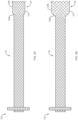
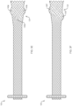
- a medical device 100 e.g. , drainage stent
- a medical device 100 may include an elongate tubular body 110 configured to move between a first (e.g. , constrained, collapsed, non-expanded) configuration and a second ( e.g. , non-constrained, expanded) configuration.
- a proximal portion 112 of the elongate tubular body 110 may form a proximal retention member 114 defining a first (e.g.
- proximal opening 116 and a distal portion 122 of the elongate tubular body 110 may form a distal retention member 124 defining a second ( e.g. , distal) opening 126.
- a cylindrical saddle region 130 with a circumference and a longitudinal axis may extend between the proximal and distal retention members 114, 124 to define an open interior passage 132 ( e.g. , channel, lumen, etc.) therebetween.
- a diameter d 3 of the cylindrical saddle region 130 may be greater than a diameter of the elongate tubular body 110 in the first configuration.
- the proximal retention member 114 may extend radially from ( e . g ., perpendicular to a circumference of) the cylindrical saddle region 130 to define a surface 115 configured to atraumatically engage a ( e.g. , inner) tissue wall of a first body lumen ( e.g. , the stomach or duodenum).
- the distal retention member 124 may form a flared end ( e.g. , flared flange structure), with an outer surface 125 of the flared end configured to atraumatically engage a ( e.g. , inner) tissue wall of an adjacent or apposed second body lumen ( e.g. , a biliary duct).
- the surfaces 115, 125 of the proximal and distal retention members 114, 124 may prevent or limit movement/migration of the deployed medical device 100 within or between the first and second body lumens.
- an outer diameter d 1 of the proximal retention member 114 may be equal to an outer diameter d 2 of the distal retention member 124.
- the cylindrical saddle region 130 may include a constant outer diameter d 3 extending between the proximal and distal retention members 114, 124, wherein the diameter d 3 of the cylindrical saddle region is less than the diameters d 1 and d 2 of the proximal and distal retention members 114, 124.
- outer diameters d 1 and d 2 may be approximately 7.0 mm to approximately 30 mm
- outer diameter d 3 may be approximately 3.0 mm to approximately 15.0 mm.
- the proximal and distal retention members 114, 124 may include an outer diameter d 1 and d 2 that is as much as 75%-100% greater than an outer diameter d 3 of the cylindrical saddle region 130.
- the cylindrical saddle region 130 may include a length of approximately 40-50 mm.
- the elongate tubular body of any of the medical devices 100, 200, 300 depicted in FIGS. 1-6 may be formed of one or more woven, braided and/or knitted filaments (e . g ., shape memory metals and polymers, nitinol wire, etc.).
- the woven, braided and/or knitted filament(s) may further include a single filament woven upon itself, or multiple filaments woven together.
- any of the woven, braided and/or knitted filament(s), which comprise the elongate tubular body may include a variety of different cross-sectional shapes (e.g. , oval, round, flat, square, etc.).
- a distal end 128 of the elongate tubular body 110 may include an atraumatic configuration in which free ends of the one or more adjacent woven, braided or knitted filaments are bent and connected to form a series of atraumatic loop ends 128a.
- each loop end 128a may be formed by mating and securing the adjacent free ends of the one or more filaments, e . g ., by a weld, solder, adhesive, clamp, crimpable hypotube, or other suitable means as are known in the art.
- a distal end 128 of the elongate tubular body may include an atraumatic configuration ( e .
- atraumatic looped ends formed at the distal end 128 of the elongate tubular body 110 may represent an approximate midpoint of the one or more filaments, and the proximal end of the elongate tubular body may be formed by the free ends of each of the one or more filaments.
- the proximal and distal ends of the elongate tubular body may include an atraumatic configuration ( e .
- proximal and distal ends of the mandrel may include a plurality of posts, pins or pegs, around which the one or more filaments are wound.
- Free ends of the one or more filaments may be joined or connected ( e.g. , using a suitable solder, glue, crimp, adhesive or resin, etc.) along an internal portion of elongate tubular body.
- free ends of the same or different filaments may be joined along a body portion of the elongate tubular body between the proximal and distal retention members, e . g ., along the cylindrical saddle region.
- loop ends 128a may include a variety of substantially angular configurations, including, by way of non-limiting example, semi-circular, semi-elliptical and other smoothly curved or substantially smoothly curved shapes.
- a proximal end 118 of the elongate tubular body 110 may include free ends 118a of the one or more woven, braided or knitted filaments which are not connected, and instead form sharp or pointed free ends of the filament(s).
- the surface 115 of the proximal retention member 114 may atraumatically engage an inner tissue wall of a first body lumen such that the free ends 118a extend into the first body lumen and do not contact the tissue wall.
- a medical device 200 of the present disclosure may include the identical, or similar, configuration and elements as medical device 100, with the exception that the distal retention member 124 includes a first portion 124a that increases in diameter towards the distal end 128, and a second portion 124b extending distally beyond the first portion that is substantially parallel to the longitudinal axis of the cylindrical saddle region 130.
- an outer surface 125 of the first and second portions 124a, 124b may atraumatically engage an inner surface of a second body lumen (e.g. , bile duct) to anchor the medical device 200.
- a second body lumen e.g. , bile duct
- any of the medical devices 100, 200 of the present disclosure may include one or more surface features (e . g ., anti-migration surface features) disposed along an outer surface of the elongate tubular body 110 and configured to atraumatically engage an inner wall of the second body lumen.
- surface features may be integrally formed from the one or more woven, braided and/or knitted filaments which form the elongate tubular body 110.
- surface features may be attached or otherwise secured to the woven, braided and/or knitted filament(s) which form the elongate tubular body 110, e.g. , using a suitable weld, solder, glue, adhesive, resin or other bonding technique, as are commonly known in the art.
- a medical device 100 may include a single surface feature 140a (e.g. , a ring or loop) extending around a full circumference of the cylindrical saddle region 130, and adjacent ( e . g ., proximal) to the distal retention member 124.
- a medical device 100 of the present disclosure may include a single surface feature 140b extending around a full circumference of the elongate tubular body 110 at an approximate junction of the cylindrical saddle region 130 and the distal retention member 124.
- a medical device 100 of the present disclosure may include a single surface feature 140c extending around a full circumference of the distal end 128 of the distal retention member 124.
- a medical device 100 of the present disclosure may include a pair of spaced-apart surface features 140d extending around a full circumference of the distal retention member 124.
- a medical device 100 of the present disclosure may include a series of bumps or projections 140e disposed in a symmetric or asymmetric pattern around a full circumference of the distal retention member 124. Referring to FIG.
- a medical device 100 of the present disclosure may include a single surface feature 140f extending in a spiral or helical configuration around a full circumference of the distal retention member 124.
- a medical device 100 of the present disclosure may include a series of surface features 140g (e.g. , undulations, bumps, etc.) extending in a symmetric or asymmetric pattern along a length of the cylindrical saddle region 130.
- the medical devices of the present disclosure are not limited to the size, shape, number, arrangement and/or spacing of surface features 140a-g depicted in FIGS. 3A-3G , but may include surface features with any number of sizes, shapes, orientations, combinations and/or variations thereof. Similar surface features may be formed along any medical device of the present disclosure for anti-migration purposes, with or without the proximal and/or distal retention member configurations specific to the present disclosure.
- a medical device 300 of the present disclosure may include the identical, or similar, configuration and elements as medical device 100 or 200, with the exception that the proximal end 118 of the elongate tubular body 110 includes an atraumatic configuration in which adjacent free ends of the one or more woven, braided or knitted filaments are bent and connected, or woven on a mandrel, to form a series of atraumatic loop ends 118b, e.g. , similar to the atraumatic loops 128a of FIG. 1 (discussed above).
- a repositioning or retrieval loop 119 e.g.
- braided-in retrieval loop may be threaded through the atraumatic loop ends 118b around a circumference of the proximal end 118 of the elongate tubular body.
- the repositioning or retrieval loop 119 may further include a projection 119a configured to be engaged ( e.g. , gripped, grasped, etc.) by a medical device ( e.g. , forceps, etc.).
- the repositioning or retrieval loop 119 may be formed from, or attached to, one or more of the woven, braided and/or knitted filaments which form the elongate tubular body 110, such that grasping and proximally retracting the projection 119a may urge the elongate tubular body 110 to move from the second configuration to the first configuration.
- a medical professional may grasp the projection 119a and exert the requisite proximal force on the retrieval loop 119 to properly position/reposition the proximal and distal retention members 114, 124 within the respective first and second body lumens.
- the medical professional may exert the requisite proximal force on the retrieval loop 119 to remove the medical device from the patient.
- suitable retrieval loops are described in U.S. Patent Publication No. 2016/0175124 and U.S. Patent No. 9,265,634 , the contents of which are hereby incorporated by reference in their entirety.
- all or a portion of the elongate tubular body 110 of any of the medical devices 100, 200, 300 depicted in FIGS. 1-6 may further include a membrane, covering or coating on an inner and/or outer surface thereof to define a contiguous open interior passage configured for controlled flow (e.g. , body fluids, materials, and the like) and/or access therethrough.
- the proximal retention member 114 and cylindrical saddle region 130 may include a membrane, covering or coating 134, and the distal retention member 124 (e.g. , the portion disposed within the second body lumen) may be uncoated, e.g.
- the coating may comprise a variety of non-degradable and biocompatible polymeric materials (e . g ., upon exposure to bodily fluids such as bile), including, for example, silicones, rubbers, polyethylenes, PVDF, Chronoflex ® and thermoplastic elastomers, such that the coating conforms to the medical device in the unexpanded and expanded configurations.
- a medical device 100, 200, 300 of the present disclosure may be disposed in the unexpanded configuration within the lumen of a delivery catheter which may include a tissue-penetrating element.
- a sharpened distal end of the tissue-penetrating element may be advanced through the tissue wall of a first body lumen 150 (e.g. , the stomach or duodenum) and into the opening of a second body lumen 160 ( e.g. , the bile duct).
- the tissue penetrating element may comprise a conductive element (e.g. , halo wire cone with proximally extending arms) that is configured to receive heat or energy (e.g. , RF energy) for the purpose of creating openings.
- the tissue penetrating element may be advanced over a guidewire previously advanced through the first body lumen 150 and into the second body lumen 160 such that a distal end of the guidewire is disposed within the second body lumen 160.
- a separate instrument with a sharpened distal tip may be advanced along the path above and into the second body lumen 160 to create a path.
- a guidewire may be put in place, or left in place, if used to guide the separate instrument, and the separate instrument withdrawn over the guidewire.
- the distal portion 122 of the medical device 100, 200, 300 may then be further advanced distally beyond the lumen of the delivery catheter (which may or may not also include tissue-penetrating element), and/or an outer sheath of the delivery catheter may be retracted from the medical device, such that the distal retention member 124 is fully deployed within the second body lumen 160 and the surface 125 of the distal retention member 124 is placed in contact with the inner surface of the tissue wall of the second body lumen 160.
- the delivery catheter which may or may not also include tissue-penetrating element
- the delivery catheter may then be further proximally retracted into the first body lumen 150, and the proximal portion 112 of the medical device 100, 200, 300 advanced distally beyond the lumen of the delivery catheter, and/or the outer sheath of the delivery catheter may be further retracted from about the medical device 100, 200, 300 such that the proximal retention member 114 is fully deployed within the first body lumen 150 and the surface 115 of the proximal retention member 114 is placed in contact with the inner surface of the tissue wall of the first body lumen 150.
- the proximal retention member 114 of any of the medical devices 100, 200, 300 depicted in FIGS. 1-6 may include various configurations which extend radially at an angle from the longitudinal axis of the elongate tubular body that is not necessarily perpendicular to the elongate tubular body and/or the surfaces are not necessarily planar.
- the angle of the proximal retention member 114 relative to the circumference and longitudinal axis of the cylindrical saddle region may assume other degrees ( e.g. , 30, 45, 60, 75 degrees, etc.) or may change degrees along the length of the proximal retention member 114 creating inflection points in the retention member.
- the proximal retention member 114 may extend outward towards an end of the elongate tubular body, back towards a center portion of the elongate tubular body, or change directions in some combination of both.
- the proximal retention member 114 may flare away from a longitudinal axis of the cylindrical saddle region 130 into a flange configuration when in the expanded configuration.
- the flange configuration may include at least first and second points of inflection that may define first and second segments of the flange.
- the first segment may extend from the first inflection point toward a center plane perpendicular to the longitudinal axis of the elongate tubular body, and the second segment may extend from the first inflection point away from the center plane.
- An angle of the first inflection point defined by the first segment and the cylindrical saddle region 130 may be at least as great as an opposing angle of the second inflection point defined by the first segment and the second segment.
- the proximal flange may include at least first and second points of inflection that define first and second segments of the flange, wherein the second points of inflection may be further spaced radially from the longitudinal axis than the first points of inflection, and the second points of inflection may be closer than the first points of inflection to a center plane along the longitudinal axis.
- the proximal flange may touch planes that are parallel to the longitudinal axis, at least one plane each above and below the longitudinal axis, at at least two separate points along the parallel planes.
- the proximal flange configuration may include at least first and second points of inflection that define first and second segments of the flange.
- the first segment may extend from the first inflection point toward a center plane perpendicular to the longitudinal axis of the elongate tubular body 110, and the second segment may extend from the second inflection point away from the center plane.
- the intersection of the cylindrical saddle region 130 and the first segments may define the first inflection points, and the intersection of the first segments and second segments may define second inflection points.
- An angle of the first inflection points may be 90 degrees or less, and an opposing angle of the second inflection points may be 90 degrees or less.
- the medical devices 100, 200, 300 of the present disclosure may include a single or double-walled flange as the proximal retention member 114 when the elongate tubular body 110 is in the expanded configuration.
- the walls of the proximal flange above and/or below the longitudinal axis may be symmetrical or may be asymmetrical.
- the walls of the proximal flange above and/or below the longitudinal axis may have multiple inflection points, as mentioned above, that define segments of the walls of the proximal flange that change direction as the walls extend radially away from the longitudinal axis ( e . g ., segments can extend radially parallel to, away from and/or toward, a radial center line of the body).
- the segments may extend along a straight line or may be curved, or may include a combination of straight lines and curves.
- the medical devices 100, 200, 300 disclosed herein are generally depicted as including woven, knitted or braided filaments ( e . g ., nitinol, etc.), in various embodiments, the medical devices may include laser cut designs which may or may not change in length ( e.g. , shorten) as the medical device moves from the first configuration to the second configuration.
- the medical devices in various configurations may be self-expanding or expandable such as balloon-expandable.
Landscapes
- Health & Medical Sciences (AREA)
- Engineering & Computer Science (AREA)
- Biomedical Technology (AREA)
- Life Sciences & Earth Sciences (AREA)
- General Health & Medical Sciences (AREA)
- Heart & Thoracic Surgery (AREA)
- Animal Behavior & Ethology (AREA)
- Public Health (AREA)
- Veterinary Medicine (AREA)
- Oral & Maxillofacial Surgery (AREA)
- Cardiology (AREA)
- Vascular Medicine (AREA)
- Transplantation (AREA)
- Pulmonology (AREA)
- Gastroenterology & Hepatology (AREA)
- Surgery (AREA)
- Physiology (AREA)
- Nuclear Medicine, Radiotherapy & Molecular Imaging (AREA)
- Medical Informatics (AREA)
- Molecular Biology (AREA)
- Ophthalmology & Optometry (AREA)
- Otolaryngology (AREA)
- Anesthesiology (AREA)
- Hematology (AREA)
- Prostheses (AREA)
- External Artificial Organs (AREA)
Applications Claiming Priority (3)
| Application Number | Priority Date | Filing Date | Title |
|---|---|---|---|
| US201862632691P | 2018-02-20 | 2018-02-20 | |
| PCT/US2019/018493 WO2019164803A1 (en) | 2018-02-20 | 2019-02-19 | Drainage device |
| EP19708747.1A EP3755266B1 (de) | 2018-02-20 | 2019-02-19 | Drainagevorrichtung |
Related Parent Applications (1)
| Application Number | Title | Priority Date | Filing Date |
|---|---|---|---|
| EP19708747.1A Division EP3755266B1 (de) | 2018-02-20 | 2019-02-19 | Drainagevorrichtung |
Publications (2)
| Publication Number | Publication Date |
|---|---|
| EP4364703A2 true EP4364703A2 (de) | 2024-05-08 |
| EP4364703A3 EP4364703A3 (de) | 2024-07-31 |
Family
ID=65635841
Family Applications (2)
| Application Number | Title | Priority Date | Filing Date |
|---|---|---|---|
| EP24166649.4A Pending EP4364703A3 (de) | 2018-02-20 | 2019-02-19 | Entwässerungsvorrichtung |
| EP19708747.1A Active EP3755266B1 (de) | 2018-02-20 | 2019-02-19 | Drainagevorrichtung |
Family Applications After (1)
| Application Number | Title | Priority Date | Filing Date |
|---|---|---|---|
| EP19708747.1A Active EP3755266B1 (de) | 2018-02-20 | 2019-02-19 | Drainagevorrichtung |
Country Status (3)
| Country | Link |
|---|---|
| US (2) | US20190254804A1 (de) |
| EP (2) | EP4364703A3 (de) |
| WO (1) | WO2019164803A1 (de) |
Families Citing this family (6)
| Publication number | Priority date | Publication date | Assignee | Title |
|---|---|---|---|---|
| KR102271744B1 (ko) * | 2018-07-25 | 2021-07-01 | 가톨릭대학교 산학협력단 | 생체 모사형 인공방광 및 이의 제어방법 |
| EP4185239A4 (de) * | 2020-07-24 | 2024-08-07 | Merit Medical Systems, Inc. | Ösophageale stents und zugehörige verfahren |
| WO2022093710A1 (en) | 2020-10-26 | 2022-05-05 | Merit Medical Systems, Inc. | Esophageal stents with helical thread |
| US20220203077A1 (en) * | 2020-12-29 | 2022-06-30 | Boston Scientific Scimed, Inc. | Drainage devices and methods of use |
| KR20250099405A (ko) * | 2022-11-23 | 2025-07-01 | 보스톤 싸이엔티픽 싸이메드 인코포레이티드 | 선택적 막 코팅을 갖는 스텐트 |
| WO2025006770A1 (en) | 2023-06-28 | 2025-01-02 | Boston Scientific Scimed, Inc. | Self-adjusting tissue lumen stents |
Citations (5)
| Publication number | Priority date | Publication date | Assignee | Title |
|---|---|---|---|---|
| US7655039B2 (en) | 2003-05-23 | 2010-02-02 | Boston Scientific Scimed, Inc. | Stents with attached looped ends |
| US9265634B2 (en) | 2005-05-13 | 2016-02-23 | Boston Scientific Scimed, Inc. | Integrated stent repositioning and retrieval loop |
| US20160175124A1 (en) | 2005-01-28 | 2016-06-23 | Boston Scientific Scimed, Inc. | Stent retrieval member and devices and methods for retrieving or repositioning a stent |
| WO2020117756A1 (en) * | 2018-12-04 | 2020-06-11 | Boston Scientific Scimed, Inc. | Device for anastomotic bypass |
| EP4442879A2 (de) * | 2019-01-07 | 2024-10-09 | Boston Scientific Scimed Inc. | Stent mit antibewegungsfunktion |
Family Cites Families (3)
| Publication number | Priority date | Publication date | Assignee | Title |
|---|---|---|---|---|
| EP2240215B1 (de) * | 2008-01-17 | 2014-01-08 | Boston Scientific Scimed, Inc. | Stent mit antibewegungsfunktion |
| CN104936557A (zh) * | 2013-03-15 | 2015-09-23 | 美国医疗设备有限公司 | 食管支架 |
| KR200498665Y1 (ko) * | 2014-06-18 | 2024-12-24 | 보스톤 싸이엔티픽 싸이메드 인코포레이티드 | 담관 스텐트 |
-
2019
- 2019-02-19 EP EP24166649.4A patent/EP4364703A3/de active Pending
- 2019-02-19 US US16/279,140 patent/US20190254804A1/en not_active Abandoned
- 2019-02-19 EP EP19708747.1A patent/EP3755266B1/de active Active
- 2019-02-19 WO PCT/US2019/018493 patent/WO2019164803A1/en not_active Ceased
-
2022
- 2022-10-10 US US17/962,701 patent/US20230036965A1/en active Pending
Patent Citations (8)
| Publication number | Priority date | Publication date | Assignee | Title |
|---|---|---|---|---|
| US7655039B2 (en) | 2003-05-23 | 2010-02-02 | Boston Scientific Scimed, Inc. | Stents with attached looped ends |
| US8109988B2 (en) | 2003-05-23 | 2012-02-07 | Boston Scientific Scimed, Inc. | Stents with attached looped ends |
| US20120101564A1 (en) | 2003-05-23 | 2012-04-26 | Boston Scientific Scimed, Inc. | Stents with attached looped ends |
| US9788979B2 (en) | 2003-05-23 | 2017-10-17 | Boston Scientific Scimed, Inc. | Stents with attached looped ends |
| US20160175124A1 (en) | 2005-01-28 | 2016-06-23 | Boston Scientific Scimed, Inc. | Stent retrieval member and devices and methods for retrieving or repositioning a stent |
| US9265634B2 (en) | 2005-05-13 | 2016-02-23 | Boston Scientific Scimed, Inc. | Integrated stent repositioning and retrieval loop |
| WO2020117756A1 (en) * | 2018-12-04 | 2020-06-11 | Boston Scientific Scimed, Inc. | Device for anastomotic bypass |
| EP4442879A2 (de) * | 2019-01-07 | 2024-10-09 | Boston Scientific Scimed Inc. | Stent mit antibewegungsfunktion |
Also Published As
| Publication number | Publication date |
|---|---|
| EP4364703A3 (de) | 2024-07-31 |
| US20230036965A1 (en) | 2023-02-02 |
| WO2019164803A1 (en) | 2019-08-29 |
| EP3755266B1 (de) | 2024-04-03 |
| EP3755266A1 (de) | 2020-12-30 |
| US20190254804A1 (en) | 2019-08-22 |
Similar Documents
| Publication | Publication Date | Title |
|---|---|---|
| US20230036965A1 (en) | Drainage device | |
| EP3634259B1 (de) | Durchflussregelstent | |
| US10206799B2 (en) | Device and method for increasing flow through the left atrial appendage | |
| EP3741325B1 (de) | Gallengangstent | |
| EP2635241B1 (de) | Vorrichtung zur positionierung einer gefässprothese bzw. eines gefässprothesensystems | |
| EP3831342B1 (de) | Dilatationsvorrichtung für prostataharnröhre | |
| US9370437B2 (en) | Stent having less invasive ends | |
| CN114502086A (zh) | 用于抽吸血栓的装置及方法 | |
| EP3399925A1 (de) | Steckverbinder zur kopplung anatomischer wände | |
| US12376977B2 (en) | Stent graft device with anchoring members having adjustable geometries | |
| CN113747861A (zh) | 用于重塑瓣膜环的系统、装置和方法 | |
| KR20140123102A (ko) | 가변 압축성을 갖는 관내 인공 삽입물 및 그 이용 방법 | |
| CN218106158U (zh) | 可回收动脉瘤辅助支架及输送系统 | |
| CN117597075A (zh) | 吻合装置、系统和方法 | |
| EP2777652A1 (de) | Ladewerkzeug zur Erfassung von Stent-Punkten | |
| HK1203804B (en) | Endoprosthesis with varying compressibility |
Legal Events
| Date | Code | Title | Description |
|---|---|---|---|
| PUAI | Public reference made under article 153(3) epc to a published international application that has entered the european phase |
Free format text: ORIGINAL CODE: 0009012 |
|
| STAA | Information on the status of an ep patent application or granted ep patent |
Free format text: STATUS: REQUEST FOR EXAMINATION WAS MADE |
|
| 17P | Request for examination filed |
Effective date: 20240327 |
|
| AC | Divisional application: reference to earlier application |
Ref document number: 3755266 Country of ref document: EP Kind code of ref document: P |
|
| AK | Designated contracting states |
Kind code of ref document: A2 Designated state(s): AL AT BE BG CH CY CZ DE DK EE ES FI FR GB GR HR HU IE IS IT LI LT LU LV MC MK MT NL NO PL PT RO RS SE SI SK SM TR |
|
| REG | Reference to a national code |
Ref country code: DE Ref legal event code: R079 Free format text: PREVIOUS MAIN CLASS: A61F0002900000 Ipc: A61F0002040000 |
|
| PUAL | Search report despatched |
Free format text: ORIGINAL CODE: 0009013 |
|
| RIN1 | Information on inventor provided before grant (corrected) |
Inventor name: CURRAN, DARREN Inventor name: WALSH, MICHAEL Inventor name: MOYLAN, SHANE, SHANDARA Inventor name: FOLAN, MARTYN G. |
|
| AK | Designated contracting states |
Kind code of ref document: A3 Designated state(s): AL AT BE BG CH CY CZ DE DK EE ES FI FR GB GR HR HU IE IS IT LI LT LU LV MC MK MT NL NO PL PT RO RS SE SI SK SM TR |
|
| RIC1 | Information provided on ipc code assigned before grant |
Ipc: A61F 2/07 20130101ALN20240621BHEP Ipc: A61F 2/90 20130101ALI20240621BHEP Ipc: A61F 2/04 20130101AFI20240621BHEP |
|
| STAA | Information on the status of an ep patent application or granted ep patent |
Free format text: STATUS: EXAMINATION IS IN PROGRESS |
|
| 17Q | First examination report despatched |
Effective date: 20260312 |