EP4364705A1 - Fördervorrichtung und medizinische vorrichtung - Google Patents
Fördervorrichtung und medizinische vorrichtung Download PDFInfo
- Publication number
- EP4364705A1 EP4364705A1 EP22831575.0A EP22831575A EP4364705A1 EP 4364705 A1 EP4364705 A1 EP 4364705A1 EP 22831575 A EP22831575 A EP 22831575A EP 4364705 A1 EP4364705 A1 EP 4364705A1
- Authority
- EP
- European Patent Office
- Prior art keywords
- conveying device
- inner tube
- tube assembly
- segment
- driving member
- Prior art date
- Legal status (The legal status is an assumption and is not a legal conclusion. Google has not performed a legal analysis and makes no representation as to the accuracy of the status listed.)
- Withdrawn
Links
Images


Classifications
-
- A—HUMAN NECESSITIES
- A61—MEDICAL OR VETERINARY SCIENCE; HYGIENE
- A61F—FILTERS IMPLANTABLE INTO BLOOD VESSELS; PROSTHESES; DEVICES PROVIDING PATENCY TO, OR PREVENTING COLLAPSING OF, TUBULAR STRUCTURES OF THE BODY, e.g. STENTS; ORTHOPAEDIC, NURSING OR CONTRACEPTIVE DEVICES; FOMENTATION; TREATMENT OR PROTECTION OF EYES OR EARS; BANDAGES, DRESSINGS OR ABSORBENT PADS; FIRST-AID KITS
- A61F2/00—Filters implantable into blood vessels; Prostheses, i.e. artificial substitutes or replacements for parts of the body; Appliances for connecting them with the body; Devices providing patency to, or preventing collapsing of, tubular structures of the body, e.g. stents
- A61F2/95—Instruments specially adapted for placement or removal of stents or stent-grafts
- A61F2/962—Instruments specially adapted for placement or removal of stents or stent-grafts having an outer sleeve
-
- A—HUMAN NECESSITIES
- A61—MEDICAL OR VETERINARY SCIENCE; HYGIENE
- A61B—DIAGNOSIS; SURGERY; IDENTIFICATION
- A61B17/00—Surgical instruments, devices or methods
- A61B17/11—Surgical instruments, devices or methods for performing anastomosis; Buttons for anastomosis
-
- A—HUMAN NECESSITIES
- A61—MEDICAL OR VETERINARY SCIENCE; HYGIENE
- A61F—FILTERS IMPLANTABLE INTO BLOOD VESSELS; PROSTHESES; DEVICES PROVIDING PATENCY TO, OR PREVENTING COLLAPSING OF, TUBULAR STRUCTURES OF THE BODY, e.g. STENTS; ORTHOPAEDIC, NURSING OR CONTRACEPTIVE DEVICES; FOMENTATION; TREATMENT OR PROTECTION OF EYES OR EARS; BANDAGES, DRESSINGS OR ABSORBENT PADS; FIRST-AID KITS
- A61F2/00—Filters implantable into blood vessels; Prostheses, i.e. artificial substitutes or replacements for parts of the body; Appliances for connecting them with the body; Devices providing patency to, or preventing collapsing of, tubular structures of the body, e.g. stents
- A61F2/02—Prostheses implantable into the body
- A61F2/04—Hollow or tubular parts of organs, e.g. bladders, tracheae, bronchi or bile ducts
- A61F2/06—Blood vessels
- A61F2/07—Stent-grafts
-
- A—HUMAN NECESSITIES
- A61—MEDICAL OR VETERINARY SCIENCE; HYGIENE
- A61F—FILTERS IMPLANTABLE INTO BLOOD VESSELS; PROSTHESES; DEVICES PROVIDING PATENCY TO, OR PREVENTING COLLAPSING OF, TUBULAR STRUCTURES OF THE BODY, e.g. STENTS; ORTHOPAEDIC, NURSING OR CONTRACEPTIVE DEVICES; FOMENTATION; TREATMENT OR PROTECTION OF EYES OR EARS; BANDAGES, DRESSINGS OR ABSORBENT PADS; FIRST-AID KITS
- A61F2/00—Filters implantable into blood vessels; Prostheses, i.e. artificial substitutes or replacements for parts of the body; Appliances for connecting them with the body; Devices providing patency to, or preventing collapsing of, tubular structures of the body, e.g. stents
- A61F2/95—Instruments specially adapted for placement or removal of stents or stent-grafts
- A61F2/962—Instruments specially adapted for placement or removal of stents or stent-grafts having an outer sleeve
- A61F2/966—Instruments specially adapted for placement or removal of stents or stent-grafts having an outer sleeve with relative longitudinal movement between outer sleeve and prosthesis, e.g. using a push rod
-
- A—HUMAN NECESSITIES
- A61—MEDICAL OR VETERINARY SCIENCE; HYGIENE
- A61B—DIAGNOSIS; SURGERY; IDENTIFICATION
- A61B17/00—Surgical instruments, devices or methods
- A61B17/11—Surgical instruments, devices or methods for performing anastomosis; Buttons for anastomosis
- A61B2017/1107—Surgical instruments, devices or methods for performing anastomosis; Buttons for anastomosis for blood vessels
-
- A—HUMAN NECESSITIES
- A61—MEDICAL OR VETERINARY SCIENCE; HYGIENE
- A61B—DIAGNOSIS; SURGERY; IDENTIFICATION
- A61B17/00—Surgical instruments, devices or methods
- A61B17/11—Surgical instruments, devices or methods for performing anastomosis; Buttons for anastomosis
- A61B2017/1135—End-to-side connections, e.g. T- or Y-connections
-
- A—HUMAN NECESSITIES
- A61—MEDICAL OR VETERINARY SCIENCE; HYGIENE
- A61B—DIAGNOSIS; SURGERY; IDENTIFICATION
- A61B17/00—Surgical instruments, devices or methods
- A61B17/11—Surgical instruments, devices or methods for performing anastomosis; Buttons for anastomosis
- A61B2017/1139—Side-to-side connections, e.g. shunt or X-connections
-
- A—HUMAN NECESSITIES
- A61—MEDICAL OR VETERINARY SCIENCE; HYGIENE
- A61F—FILTERS IMPLANTABLE INTO BLOOD VESSELS; PROSTHESES; DEVICES PROVIDING PATENCY TO, OR PREVENTING COLLAPSING OF, TUBULAR STRUCTURES OF THE BODY, e.g. STENTS; ORTHOPAEDIC, NURSING OR CONTRACEPTIVE DEVICES; FOMENTATION; TREATMENT OR PROTECTION OF EYES OR EARS; BANDAGES, DRESSINGS OR ABSORBENT PADS; FIRST-AID KITS
- A61F2/00—Filters implantable into blood vessels; Prostheses, i.e. artificial substitutes or replacements for parts of the body; Appliances for connecting them with the body; Devices providing patency to, or preventing collapsing of, tubular structures of the body, e.g. stents
- A61F2/95—Instruments specially adapted for placement or removal of stents or stent-grafts
- A61F2/9517—Instruments specially adapted for placement or removal of stents or stent-grafts handle assemblies therefor
-
- A—HUMAN NECESSITIES
- A61—MEDICAL OR VETERINARY SCIENCE; HYGIENE
- A61F—FILTERS IMPLANTABLE INTO BLOOD VESSELS; PROSTHESES; DEVICES PROVIDING PATENCY TO, OR PREVENTING COLLAPSING OF, TUBULAR STRUCTURES OF THE BODY, e.g. STENTS; ORTHOPAEDIC, NURSING OR CONTRACEPTIVE DEVICES; FOMENTATION; TREATMENT OR PROTECTION OF EYES OR EARS; BANDAGES, DRESSINGS OR ABSORBENT PADS; FIRST-AID KITS
- A61F2/00—Filters implantable into blood vessels; Prostheses, i.e. artificial substitutes or replacements for parts of the body; Appliances for connecting them with the body; Devices providing patency to, or preventing collapsing of, tubular structures of the body, e.g. stents
- A61F2/95—Instruments specially adapted for placement or removal of stents or stent-grafts
- A61F2/958—Inflatable balloons for placing stents or stent-grafts
- A61F2002/9583—Means for holding the stent on the balloon, e.g. using protrusions, adhesives or an outer sleeve
-
- A—HUMAN NECESSITIES
- A61—MEDICAL OR VETERINARY SCIENCE; HYGIENE
- A61F—FILTERS IMPLANTABLE INTO BLOOD VESSELS; PROSTHESES; DEVICES PROVIDING PATENCY TO, OR PREVENTING COLLAPSING OF, TUBULAR STRUCTURES OF THE BODY, e.g. STENTS; ORTHOPAEDIC, NURSING OR CONTRACEPTIVE DEVICES; FOMENTATION; TREATMENT OR PROTECTION OF EYES OR EARS; BANDAGES, DRESSINGS OR ABSORBENT PADS; FIRST-AID KITS
- A61F2250/00—Special features of prostheses classified in groups A61F2/00 - A61F2/26 or A61F2/82 or A61F9/00 or A61F11/00 or subgroups thereof
- A61F2250/0058—Additional features; Implant or prostheses properties not otherwise provided for
- A61F2250/0096—Markers and sensors for detecting a position or changes of a position of an implant, e.g. RF sensors, ultrasound markers
- A61F2250/0098—Markers and sensors for detecting a position or changes of a position of an implant, e.g. RF sensors, ultrasound markers radio-opaque, e.g. radio-opaque markers
Definitions
- the present invention relates to the technical field of medical instruments and, more specifically, to a conveying device and a medical device.
- Transjugular intrahepatic portosystemic shunt is a minimally invasive treatment technology that implants a stent between the portal vein and hepatic vein and establishes a portosystemic shunt channel to reduce portal vein pressure. It is used to treat portal hypertension, refractory ascites, esophageal and gastric variceal bleeding caused by portal hypertension and other conditions.
- transjugular intrahepatic puncture is first performed to establish an artificial channel, and then the covered stent for TIPS is transported along the artificial channel and released at the target location, thereby establishing a portosystemic shunt channel and reducing blood flow pressure in the portal vein.
- the covered stent for TIPS usually include a bare segment and a covered segment.
- the bare segment has a length about 20 mm, and is used to be positioned in the portal vein to ensure that the blood perfusion from the portal vein to other branches is not affected.
- the covered segment has a length about 40mm-80mm, and is used to be positioned in the liver and hepatic vein to effectively prevent from bile erosion.
- the introduction path of the covered stent for TIPS is as follows: it first enters the inferior vena cava through the jugular vein approach, then enters the hepatic vein through the inferior vena cava, then exits from the hepatic vein puncture port and passes through the liver parenchyma into the portal vein, and then the bare segment is released in the portal vein, the conveying device and the covered stent for TIPS are then withdrawn as a whole until the junction between the bare segment and the covered segment coincides with the portal vein puncture port, and finally the covered segment is released.
- the conveying device in the prior art releases the covered segment, the coated segment is prone to jump forward, causing the covered segment to at least partially enter the portal vein, thereby causing the risk of blocking the portal vein branches.
- An object of the present invention is to provide a conveying device and a medical device, which can be used to release a medical stent and can effectively prevent the medical stent from jumping forward during release and improve the positioning accuracy of the medical stent when released.
- the present invention provides a conveying device, comprising a catheter mechanism and a limiting body; wherein the catheter mechanism comprises an inner tube assembly and an outer tube, and the outer tube is sleeved on the inner tube assembly and is configured to be movable along an axial direction of the inner tube assembly; the limiting body is connected to a distal outer surface of the inner tube assembly and is configured to expand or contract along a radial direction of the inner tube assembly; the conveying device is configured such that the catheter mechanism is configured to load a medical stent and to release the medical stent when the outer tube moves from distal to proximal, and the limiting body is configured to expand when the medical stent is released so as to position the medical stent in a target position.
- the medical stent comprises a covered segment and a bare segment connected to a distal end of the covered segment; wherein the conveying device is configured such that the limiting body applies a radial expansion force to the bare segment when the bare segment is released and the limiting body expands so as to expands the bare segment until a current outer surface thereof is larger than a outer surface in a natural state.
- the limiting body comprises a balloon.
- the conveying device further comprises a first developing element configured to indicate a position of the limiting body.
- the inner tube assembly comprises a first tube body and a second tube body sleeved on the first tube body, and a fluid channel is formed between an inner wall of the second tube body and an outer wall of the first tube body;
- the balloon is sleeved on the first tube body, the balloon has a distal end connected to a distal end of the first tube body, and a proximal end connected to a distal end of the second tube body, and the balloon is in communication with the fluid channel.
- the inner tube assembly further comprises a third tube body, a fourth tube body and a lubrication tube; both the third tube body and the fourth tube body are sleeved on the second tube body, a proximal end of the fourth tube body is connected to a distal end of the third tube body, and the fourth tube body has a cylindrical spring structure extending along an axis of the inner tube assembly; the lubrication tube is sleeved on the fourth tube body; and/or the inner tube assembly further comprises an ejection head connected to a distal end of the fourth tube body, a first step surface facing toward a distal end of the inner tube assembly is formed on the ejection head, and the first step surface is configured to abut against a proximal end of the medical stent.
- the outer tube comprises a lubrication layer, a metal braided layer and a basal layer, which are arranged in sequence from inside to outside.
- the outer tube further comprises a plurality of fibers evenly arranged along a circumferential direction of the outer tube, and each of the fibers is arranged between the lubrication layer and the metal braided layer and extends along an axial direction of the outer tube.
- the conveying device further comprises a guide mechanism connected to a distal end of the inner tube assembly; the guide mechanism has a proximal end configured to be disposed inside the outer tube, and a distal outer surface smoothly transiting to an outer surface of the outer tube.
- the conveying device further comprises a handle assembly comprising a housing, a transmission member and a driving member; the housing is connected to a proximal end of the inner tube assembly and is configured to remain stationary relative to the inner tube assembly; the transmission member is partially disposed inside the housing and is connected to a proximal end of the outer tube; the driving member is disposed on the housing and is configured to drive the transmission member to move along the axial direction of the inner tube assembly so as to drive the outer tube to move along the axial direction of the inner tube assembly.
- the housing defines thereon an avoidance slot extending along the axial direction of the inner tube assembly;
- the transmission member comprises a rack partially disposed inside the housing, and the rack comprises teeth extending out of the housing from the avoidance slot;
- the driving member is sleeved on the housing, and a inner wall of the driving member is provided with internal threads that engage with the rack;
- the conveying device is configured such that the driving member and the transmission member form a screw transmission when the driving member rotates around an axis of the inner tube assembly, so that the transmission member is driven to move along the axial direction of the inner tube assembly;
- the conveying device is further configured such that the transmission member is driven to move along the axial direction of the inner tube assembly when the driving member moves on the housing along the axial direction of the inner tube assembly.
- the handle assembly further comprises a locking structure provided on the housing and configured to selectively connect with or disconnect from the driving member; when the locking structure is connected to the driving member, the driving member is prevented from driving the transmission member to move along the axial direction of the inner tube assembly; when the locking structure is disconnected from the driving member, the driving member is allowed to drive the transmission member to move along the axial direction of the inner tube assembly.
- a locking structure provided on the housing and configured to selectively connect with or disconnect from the driving member; when the locking structure is connected to the driving member, the driving member is prevented from driving the transmission member to move along the axial direction of the inner tube assembly; when the locking structure is disconnected from the driving member, the driving member is allowed to drive the transmission member to move along the axial direction of the inner tube assembly.
- the driving member defines on an inner wall thereof a wavy locking groove extending in a circle along a circumferential direction of the inner tube assembly;
- the locking structure comprises an operating member and a locking member;
- the operating member is partially located inside the housing and is rotatably connected to the housing;
- the operating member has a rotation axis parallel to an axis of the inner tube assembly;
- the locking member comprises an eccentric boss provided inside the housing and connected to the operating member, and the eccentric boss is configured to rotate with a rotation of the operating member;
- the conveying device is configured such that the locking structure is connected to the driving member when the eccentric boss is at least partially inserted into the locking groove and abuts against a wall of the locking groove, and that the locking structure is disconnected from the driving member when the operating member rotates to drive the eccentric boss to separate from the locking groove.
- the present invention also provides a medical device, comprising the conveying device according to the above medical stent, wherein the medical stent comprises a covered segment and a bare segment connected to a distal end of the covered segment; the medical stent is configured to be sleeved on a distal end of the inner tube assembly of the conveying device and compressed within the outer tube of the conveying device, and the bare segment covers the limiting body of the conveying device.
- the medical stent comprises a second developing element disposed at a junction between the covered segment and the bare segment.
- the aforementioned medical device includes a conveying device and a medical stent
- the conveying device includes a catheter mechanism and a limiting body.
- the catheter mechanism includes an inner tube assembly and an outer tube.
- the outer tube is sleeved on the inner tube assembly and is configured to be movable along the axial direction of the inner tube assembly.
- the limiting body is connected to the distal outer surface of the inner tube assembly, and is configured to be able to expand or contract along the radial direction of the inner tube assembly.
- the medical stent includes a covered segment and a bare segment. The bare segment is connected to the distal end of the covered segment.
- the medical stent is configured to be sleeved on the inner tube assembly and compressed in the outer tube.
- the position and posture of the medical stent is adjusted so that the junction between the bare segment and the covered segment coincides with the puncture port of the portal vein, and then the limiting body can be radially expand to provides a radial expansion force to the bare segment, so that the bare segment is further expanded until its current outer diameter is greater than the outer diameter in its natural state.
- each embodiment described below has one or more technical features, but this does not mean that the inventor must implement all the technical features in any embodiment at the same time, or can only implement some or all of the technical features in different embodiments separately.
- those skilled in the art can selectively implement some or all of the technical features in any embodiment based on the disclosure of the present invention and design specifications or implementation requirements, or selectively implement a combination of some or all of the technical features in multiple embodiments, thereby increasing the flexibility of the implementation of the present invention.
- the singular forms “a”, “an” and “the” include plural referents, and the plural form “plurality” includes two or more referents unless the content clearly dictates otherwise.
- the term “or” is generally used in its sense including “and/or” unless the content clearly dictates otherwise, and the terms “mounted”, “connected,” and “coupled” shall be understood in a broad sense, for example, it can be a fixed connection, a detachable connection, or an integral connection.
- the connection can be mechanical or electrical. It can be a direct connection or an indirect connection through an intermediary. It can be an internal connection between two elements or an interaction between two elements.
- the specific meanings of the above terms in the present invention can be understood according to specific circumstances.
- proximal end and distal end are relative orientations, relative positions and directions of elements or actions relative to each other from the perspective of a surgeon using the medical instruments.
- proximal end and distal end are not restrictive, the “proximal end” generally refers to the end of the medical device that is close to the surgeon during normal operation, while the “distal end” generally refers to the end that first enters the patient.
- the core object of the present invention is to provide a conveying device and a medical device including the conveying device.
- the medical device also includes a medical stent.
- the conveying device is configured to load the medical stent and convey the medical stent to and release it at the target position in the patient's body.
- the conveying device includes a catheter mechanism and a limiting body.
- the catheter mechanism includes an inner tube assembly and an outer tube sleeved on the inner tube assembly, and the outer tube is configured to be movable along the axial direction of the inner tube assembly.
- the limiting body is connected to the distal outer surface of the inner tube assembly and is configured to expand or contract along the radial direction of the inner tube assembly.
- the medical stent includes a covered segment and a bare segment, and the bare segment is connected to the distal end of the covered segment.
- the medical stent of the medical device is configured to be sleeved on the distal end of the inner tube assembly and compressed inside the outer tube, and the bare segment covers the limiting body.
- the medical device can be used for transjugular intrahepatic portosystemic shunt, and the medical stent is thus a covered stent for TIPS.
- the conveying device is configured to convey the medical stent into the human body and release the bare segment in the portal vein, and release the covered segment within the liver parenchyma.
- the operator can radially expand the limiting body through relevant operations, and then the limiting body provides a radial expansion force to the bare segment, so that the bare segment is further expanded until its current outer diameter is greater than the outer diameter in its natural state.
- the medical stent provides a greater radial expansion force to the puncture port of the portal vein so as to fix the medical stent.
- the covered segment is released.
- the covered segment is prevented from jumping forward, thereby improving the positioning accuracy in the release of the medical stent.
- the outer diameter in its natural state refers to the outer diameter of the bare segment when the medical stent is not subjected to a radial force (including a radial extrusion force and a radial expansion force).
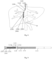
- Fig. 1 is a schematic diagram showing an overall structure of a conveying device of a medical device according to an embodiment of the application
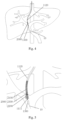
- Fig. 2 is a schematic diagram showing a partially enlarged view of a medical device in an state
- Fig. 3 is a schematic diagram showing a partially enlarged view of a medical device in another state.
- the medical device includes a conveying device 1000 and a medical stent 2000.
- the conveying device 1000 includes a catheter mechanism 1100 and a limiting body 1200.
- the catheter mechanism 1100 includes an inner tube assembly 1110 and an outer tube 1120.
- the outer tube 1120 is sleeved on the inner tube assembly 1110 and is configured to be movable along the axial direction of the inner tube assembly 1110.
- the limiting body 1200 is connected to the distal outer surface of the inner tube assembly 1110 and is configured to expand or contract along the radial direction of the inner tube assembly 1110.
- the medical stent 2000 includes a covered segment 2100 and a bare segment 2200.
- the bare segment 2200 is connected to the distal end of the covered segment 2100.
- the medical stent 2000 is used to be sleeved on the distal end of the inner tube assembly 1110 and compressed into the outer tube 1120, and the bare segment 2200 covers the limiting body 1200.
- the conveying device 1000 When transjugular intrahepatic portosystemic shunt is performed, as shown in Figs. 4 to 8 , the conveying device 1000 first conveys the medical stent 2000 into the human body so that at least the bare segment 2200 completely accesses to the portal vein after passing through the jugular vein, inferior vena cava, right hepatic vein, and liver parenchyma. The operator then controls the outer tube 1120 to move from distal to proximal to release the bare segment 2200. After that, the position and posture of the medical stent 2000 is adjusted so that the junction between the bare segment 2200 and the covered segment 2100 coincides with the puncture port of the portal vein.
- the operator then performs relevant operations to radially expand the limiting body 1200 so that the limiting body 1200 applies a radial expansion force to the bare segment 2200 to cause the bare segment 2200 to further expand until is current outer diameter is greater than the outer diameter in its natural state.
- the junction between the bare segment 2200 and the covered segment 2100 applies a great radial support force to the portal vein puncture port so that the medical stent 2000 is fixed under the pressure of the portal vein puncture port.
- the operator controls the outer tube 1120 to move from distal to proximal to release the covered segment 2100. Since the medical stent 2000 has been fixed, the covered segment 2100 can be prevented from jumping due to the sudden change of radial force when released. Therefore, the shift of the medical stent 2000 is avoided, and the positioning accuracy of the medical stent 2000 is improved.
- the conveying device 1000 further includes a first developing element 1001 configured to indicate the position of the limiting body 1200.
- the medical stent 2000 further includes a second developing element 2300 configured to indicate the position of the junction between the covered segment 2100 and the bare segment 2200.
- the second developing element 2300 is preferably provided at the junction between the covered segment 2100 and the bare segment 2200.
- the limiting body 1200 includes a balloon.
- the inner tube assembly 1110 includes a first tube body 1111 and a second tube body 1112.
- the second tube body 1112 is sleeved on the first tube body 1111, and a fluid channel (not labeled in the figure) is formed between the inner wall of the second tube body 1112 and the outer wall of the first tube body 1111.
- the balloon is sleeved on the first tube body 1111, the distal end of the balloon is connected to the distal end of the first tube body 1111, and the proximal end of the balloon is connected to the distal end of the second tube body 1112, and the balloon is also in communication with the fluid channel.
- the operator can inject the filling agent into the balloon through the fluid channel to inflate the balloon (that is, to radially expand the balloon), and discharge the filling agent from the balloon to deflate the balloon (that is, to radially contract the balloon).
- the filling agent is, for example, contrast agent or physiological saline.
- the number of the first developing elements 1001 may be two, and the two first developing elements 1001 are disposed on the outer surface of the first tube body 1111 and arranged in correspondence to the proximal and distal ends of the balloons respectively.
- the inner tube assembly 1110 further includes a third tube body 1113, a fourth tube body 1114 and a lubrication tube 1115.
- the third tube body 1113 and the fourth tube body 1114 are both sleeved on the second tube body 1112, and the proximal end of the fourth tube body 1114 is connected to the distal end of the third tube body 1113.
- the fourth tube body 1114 has a cylindrical spring structure formed by spirally winding a wire around the axis of the inner tube assembly 1110. Such a structure is conducive to improving the flexibility of the inner tube assembly 1110 so that it is easier to pass through tortuous blood vessels.
- the lubrication tube 1115 is sleeved on the fourth tube body 1114.
- the lubrication tube 1115 is, for example, a PTFE tube, which is fixed on the outer surface of the fourth tube body 1114 through heat shrink process to reduce the friction force generated from the axial movement of the outer tube 1120 relative to the inner tube assembly 1110.
- the inner tube assembly 1110 further includes an ejection head 1116 connected to the distal end of the fourth tube body 1114.
- the ejection head 1116 includes a first segment 1116a and a second segment 1116b which is closer to the distal end of the inner tube assembly 1110.
- the outer diameter of the second segment 1116b is smaller than the outer diameter of the first segment 1116a. In this way, the first step surface 1116c facing toward the distal end of the inner tube assembly 1110 is formed on the ejection head 1116.
- the first step surface 1116c is configured to abut against the proximal end of the medical stent 2000, so that the medical stent 2000 can be positionally limited by the first step surface 1116c when the outer tube 1120 moves from distal to proximal. As a result, the medical stent 2000 is prevented from moving proximally along with the outer tube 1120 under the action of the friction force, thereby ensuring smooth release of the medical stent 2000.
- the conveying device further includes a guide mechanism 1300.
- the guide mechanism 1300 is connected to the distal end of the inner tube assembly 1110, and configured to guide the conveying device 1000.
- the outer diameter of the guide mechanism 1300 first increases and then decreases from proximal to distal.
- the guide mechanism 1300 has an axial through hole 1310.
- the through hole 1310 includes a proximal segment 1311 and a distal segment 1312 (labeled in Fig. 12 ) which are in communication with each other.
- the proximal segment 1311 is connected to the distal end of the first tube body 1111 of the inner tube assembly 1110, so that the inner cavity of the first tube body 1111 communicates with the distal segment 1312 and is configured for passing the guide wire 10 (labeled in Figs. 4 to 8 ).
- the guide mechanism 1300 can travel along the guide wire 10 in the human body and guide the conveying device 1000 to a predetermined position in the human body.
- a second step surface 1320 facing toward the proximal end of the inner tube assembly 1110 is formed on the outer wall of the guide mechanism 1300.
- the second step surface 1320 is configured to abut against the distal end surface of the outer tube 1120.
- the situation in which the distal end surface of the outer tube 1120 abuts against the second step surface 1320 is herein referred to as the catheter mechanism 1100 being in a closed state. It can be understood that when the catheter mechanism 1100 is in the closed state, the portion of the guide mechanism 1300 proximal to the second step surface 1320 is located inside the outer tube 1120.
- the portion of the outer surface of the guide mechanism 1300 which is distal to the second step surface 1320 smoothly transits to the outer surface of the outer tube 1120. This is advanced in that the conveying device 1000 will not scratch the patient's tissue during its movement in the human body.
- the guide mechanism 1300 further defines on its outer surface a discharge groove 1330.
- the discharge groove 1330 is in communication with the inner cavity of the outer tube 1120 and is configured to discharge the gas or liquid from the outer tube 1120.
- the conveying device 1000 also includes a handle assembly 1400.
- the handle assembly 1400 includes a housing 1410, a transmission member 1420 and a driving member 1430.
- the housing 1410 is connected to the proximal end of the inner tube assembly 1110 (specifically, connected to the proximal end of the third tube body 1113) and is configured to remain stationary relative to the inner tube assembly 1110.
- the transmission member 1420 is partially disposed inside the housing 1410 and connected to the proximal end of the outer tube 1120.
- the driving member 1430 is disposed on the housing 1410 and is configured to drive the transmission member 1420 to move along the axial direction of the inner tube assembly 1110, and thereby drive the outer tube 1120 to move along the axial direction of the inner tube assembly 1110.
- the housing 1410 defines thereon an avoidance slot (not shown in the figures) extending along the axial direction of the inner tube assembly 1110.
- the transmission member 1420 includes a rack 1421 partially disposed inside the housing 1410. The teeth of the rack 1421 extend out of the housing 1410 from the avoidance slot.
- the driving member 1430 is sleeved on the housing 1410, and the inner wall of the driving member 1430 is provided with internal threads that engage with the rack 1421.
- the conveying device is configured such that the driving member 1430 and the rack 1421 form a screw transmission when the driving member 1430 rotates around the axis of the inner tube assembly 1110, so that the transmission member 1420 moves along the axial direction of the inner tube assembly 1110.
- the transmission member 1420 is driven to move along the axial direction of the inner tube assembly 1110.
- the driving member 1430 can either drive the transmission member 1420 to move along the axial direction of the inner tube assembly 1110 through screw transmission, or drive the transmission member along the axial direction of the inner tube assembly 1110 through direct pulling.
- the screw transmission is characterized in that it is stable and the stroke can be controlled more accurately, while the direct pulling allows a rapid movement. Therefore, when releasing the medical stent 2000, the operator can first release the bare segment 2200 through screw transmission, and then release the covered segment 2100 through direct pulling.
- the proximal end of the inner tube assembly 1110 may extend out of the housing 1410 and be connected to a connector assembly 1500 (as shown in Fig. 1 ).
- the connector assembly 1500 includes a first connector 1510 and a second connector 1520.
- the first connector 1510 is in communication with the inner cavity of the first tube body 1111 of the inner tube assembly 1110 and is used for passing the guide wire 10.
- the second connector 1520 is in communication with the fluid channel of the inner tube assembly 1110 and is used for filling or discharging the filling agent.
- the transmission member 1420 further includes two transmission and engagement members, which are a first transmission and engagement member 1422a and a second transmission and engagement member 1422b.
- the first transmission and engagement member 1422a is injection molded on the proximal end of the outer tube 1120.
- the second transmission and engagement member 1422b is sleeved on the inner tube assembly 1110.
- the distal end of the second transmission and engagement member 1422b is threadedly connected to the first transmission and engagement member 1422a.
- the proximal end of the second transmission and engagement member 1422b is connected to the distal end of the rack 1421.
- the conveying device 1000 also includes an infusion assembly 1600.
- One end of the infusion assembly 1600 extends into the interior of the housing 1410 and is connected to the second transmission and engagement member 1422b, and is in communication with the outer tube 1120 so as to allow liquid to be infused into the patient's body through the inner cavity of the outer tube 1120, or to allow liquid or gas to be discharged from the patient's body through the inner cavity of the outer tube 1120.
- the handle assembly 1400 further includes a locking structure 1440, which is provided on the housing 1410 and configured to selectively engage with or disengage from the driving member 1430.
- a locking structure 1440 is provided on the housing 1410 and configured to selectively engage with or disengage from the driving member 1430.
- the driving member 1430 is prevented from driving the transmission member 1420 to move along the axial direction of the inner tube assembly 1110.
- the driving member 1430 is allowed to drive the transmission member 1420 to move along the axial direction of the inner tube assembly 1110.
- the locking structure 1440 when the locking structure 1440 is connected to the driving member 1430, it actually prevents the driving member 1430 from moving on the housing 1410 (i.e., from rotating around the axis of the inner tube assembly 1110 or moving along the axis of the inner tube assembly 1110), thereby preventing the driving member 1430 from driving the transmission member 1420 to move.
- the driving member 1430 defines on its inner wall a wavy locking groove 1431 extending in a circle along the circumferential direction of the inner tube assembly 1110.
- the locking groove 1431 is preferably defined at the distal end of the driving member 1430.
- the locking structure 1440 includes an operating member 1441 and a locking member 1442. A part of the operating member 1441 is located inside the housing 1410 and the other part is located outside the housing 1410 to facilitate the operator's operation.
- the operating member 1441 is rotatably connected to the housing 1410.
- the housing 1410 is provided with a seat 1411, and the operating member 1441 is rotatably connected to the seat 1411.
- the rotation axis of the operating member 1441 is parallel to the axis of the inner tube assembly 1110.
- the locking member 1442 includes an eccentric boss 1442, which is connected to the operating member 1441 and configured to rotate with the rotation of the operating member 1441.
- the eccentric boss 1442 is at least partially inserted into the locking groove 1431 and abuts against the wall of the locking groove 1431, the locking structure 1440 is connected to the driving member 1430.
- the locking structure 1440 is disconnected from the driving member 1430.
- the unlocking direction can also be marked on the seat 1411. When the operator rotates the operating member 1441 in the unlocking direction, the connection between the locking structure 1440 and the driving member 1430 can be smoothly released.
- the locking structure 1440 remains connected to the driving member 1430.
- the operator rotates the operating member 1441 and releases the connection between the locking structure 1440 and the driving member 1430.
- the operator rotates the driving member 1430 in the first direction to slowly and steadily release the bare segment 2200 of the medical stent 2000.
- the operator injects filling agent into the balloon to expand the balloon.
- the operator pulls the driving member 1430 proximally to quickly release the covered segment 2100 of the medical stent 2000.
- the operator discharges the filling agent from the balloon to cause the balloon to shrink.
- the operator also controls the driving member 1430 to move the outer tube 1120 from proximal to distal, and rotates the driving member 1430 in the second direction until the catheter mechanism 1100 is closed, and finally the conveying device 1000 is withdrawn from the patient's body.
- the second direction is opposite to the first direction.
- the handle assembly 1400 further includes a stopper 1450, which is configured to prevent the driving member 1430 from being separated from the transmission member 1420.
- the number of the stopper 1450 may be one, and the stopper 1450 is provided at the proximal end of the rack 1421 in order to prevent the driving member 1430 from being separated at the proximal end of the rack 1421 from the transmission member 1420 when the operator rotates the driving member 1430 in the second direction.
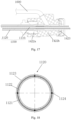
- the outer tube 1120 includes a lubrication layer 1121, a metal braided layer 1122 and a basal layer 1123, which are arranged in sequence from the inside to the outside.
- the material of the lubrication layer 1121 may be PTFE, which has a small friction coefficient and is beneficial to reducing the frictional force between the medical stent 2000 and the inner tube assembly 1110, which is generated from the movement of the outer tube 1120 along the axial direction of the inner tube assembly 1110. This reduces the resistance when the medical stent 2000 is released.
- the metal braided layer 1122 can be formed by braiding at least one metal wire.
- the way of braiding for forming the metal braided layer 1122 is not particularly limited.
- one metal wire is alternated with another metal wire in sequence.
- the arrangement of the metal braided layer 1122 can effectively reduce the outer diameter of the outer tube 1120 and reduce the outer diameter of the conveying device while ensuring the torsion control and support of the outer tube 1120.
- the basal layer 1123 may be made of Pebax.
- the outer tube 1120 further includes a plurality of fibers 1124.
- the number of the fibers 1124 is usually four, and the four fibers 1124 are evenly arranged between the metal braided layer 1122 and the lubrication layer 1121 along the circumferential direction of the outer tube 1120.
- Each fiber 1124 extends along the axial direction of the outer tube 1120.
- the fiber 1124 may be made of aromatic liquid crystal polyester, which is used to strengthen the axial strength of the outer tube 1120.
- the limiting body is used to provide radial support force to the bare segment, so that the bare segment further radially expands, thereby increasing the radial support force exerted on the portal vein puncture port from the junction between the bare segment and the covered segment, and under the action of this radial support force, the medical stent is maintained at the target position and is prevented from jumping forward when the covered segment is released. Therefore, the displacement of the medical stent is avoided.
Landscapes
- Health & Medical Sciences (AREA)
- Engineering & Computer Science (AREA)
- Biomedical Technology (AREA)
- Life Sciences & Earth Sciences (AREA)
- Animal Behavior & Ethology (AREA)
- Veterinary Medicine (AREA)
- Public Health (AREA)
- Heart & Thoracic Surgery (AREA)
- General Health & Medical Sciences (AREA)
- Transplantation (AREA)
- Vascular Medicine (AREA)
- Oral & Maxillofacial Surgery (AREA)
- Cardiology (AREA)
- Surgery (AREA)
- Nuclear Medicine, Radiotherapy & Molecular Imaging (AREA)
- Medical Informatics (AREA)
- Molecular Biology (AREA)
- Gastroenterology & Hepatology (AREA)
- Pulmonology (AREA)
- Media Introduction/Drainage Providing Device (AREA)
Applications Claiming Priority (2)
| Application Number | Priority Date | Filing Date | Title |
|---|---|---|---|
| CN202110735964.0A CN115531057A (zh) | 2021-06-30 | 2021-06-30 | 一种输送装置及医用装置 |
| PCT/CN2022/095872 WO2023273753A1 (zh) | 2021-06-30 | 2022-05-30 | 一种输送装置及医用装置 |
Publications (2)
| Publication Number | Publication Date |
|---|---|
| EP4364705A1 true EP4364705A1 (de) | 2024-05-08 |
| EP4364705A4 EP4364705A4 (de) | 2024-10-09 |
Family
ID=84692504
Family Applications (1)
| Application Number | Title | Priority Date | Filing Date |
|---|---|---|---|
| EP22831575.0A Withdrawn EP4364705A4 (de) | 2021-06-30 | 2022-05-30 | Fördervorrichtung und medizinische vorrichtung |
Country Status (4)
| Country | Link |
|---|---|
| US (1) | US20240139009A1 (de) |
| EP (1) | EP4364705A4 (de) |
| CN (1) | CN115531057A (de) |
| WO (1) | WO2023273753A1 (de) |
Families Citing this family (1)
| Publication number | Priority date | Publication date | Assignee | Title |
|---|---|---|---|---|
| CN117717447B (zh) * | 2023-12-28 | 2025-01-07 | 广东博迈医疗科技股份有限公司 | 用于输送自膨胀式支架的输送装置 |
Family Cites Families (19)
| Publication number | Priority date | Publication date | Assignee | Title |
|---|---|---|---|---|
| US5976178A (en) * | 1996-11-07 | 1999-11-02 | Vascular Science Inc. | Medical grafting methods |
| JP4731471B2 (ja) * | 2003-04-16 | 2011-07-27 | ジェネシス・テクノロジーズ・エルエルシー | 医療機器と方法 |
| US7998112B2 (en) * | 2003-09-30 | 2011-08-16 | Abbott Cardiovascular Systems Inc. | Deflectable catheter assembly and method of making same |
| JP2012200368A (ja) * | 2011-03-24 | 2012-10-22 | Terumo Corp | ステントデリバリーシステム |
| CN102274575B (zh) * | 2011-05-17 | 2013-07-17 | 上海微创医疗器械(集团)有限公司 | 一种球囊扩张导管 |
| JP2015066007A (ja) * | 2013-09-26 | 2015-04-13 | 株式会社 京都医療設計 | 医療用のカテーテル装置 |
| CN206214242U (zh) * | 2016-07-29 | 2017-06-06 | 孙英贤 | 支架输送系统 |
| CN107080609A (zh) * | 2017-05-31 | 2017-08-22 | 苏州大学 | 一种适用于肠道支架的导入装置及其使用方法 |
| US20190008629A1 (en) * | 2017-07-07 | 2019-01-10 | Abbott Cardiovascular Systems Inc. | Scaffold delivery |
| CN107468379B (zh) * | 2017-09-11 | 2023-09-08 | 姜正明 | 一种主动脉瓣膜支架输送系统及主动脉瓣膜系统 |
| WO2019180928A1 (ja) * | 2018-03-23 | 2019-09-26 | 朝日インテック株式会社 | バルーンカテーテル |
| CN112423824B (zh) * | 2018-05-17 | 2023-02-21 | 92号医疗公司 | 抽吸导管系统和使用方法 |
| CN209661891U (zh) * | 2018-12-29 | 2019-11-22 | 上海微创心脉医疗科技股份有限公司 | 医用植入物的输送系统 |
| CN111374813B (zh) * | 2018-12-29 | 2024-12-06 | 上海微创心通医疗科技有限公司 | 支架输送装置和支架装载方法 |
| CN109662821A (zh) * | 2019-01-15 | 2019-04-23 | 李卫校 | 支架快速输送释放模块及支架快速输送释放器 |
| CN110876633B (zh) * | 2019-12-03 | 2024-06-14 | 江苏博朗森思医疗器械有限公司 | 一种可降解封堵器的专用输送器 |
| CN112972082A (zh) * | 2021-05-12 | 2021-06-18 | 上海微创心脉医疗科技(集团)股份有限公司 | 一种医用支架 |
| CN215821294U (zh) * | 2021-06-30 | 2022-02-15 | 上海拓脉医疗科技有限公司 | 一种输送装置及医用装置 |
| BR112023004880A2 (pt) * | 2022-02-08 | 2023-11-14 | Sahajanand Medical Tech Limited | Cateter percutâneo para aplicação de um implante |
-
2021
- 2021-06-30 CN CN202110735964.0A patent/CN115531057A/zh active Pending
-
2022
- 2022-05-30 EP EP22831575.0A patent/EP4364705A4/de not_active Withdrawn
- 2022-05-30 WO PCT/CN2022/095872 patent/WO2023273753A1/zh not_active Ceased
- 2022-05-30 US US18/565,937 patent/US20240139009A1/en active Pending
Also Published As
| Publication number | Publication date |
|---|---|
| US20240139009A1 (en) | 2024-05-02 |
| WO2023273753A1 (zh) | 2023-01-05 |
| EP4364705A4 (de) | 2024-10-09 |
| CN115531057A (zh) | 2022-12-30 |
Similar Documents
| Publication | Publication Date | Title |
|---|---|---|
| CN215821294U (zh) | 一种输送装置及医用装置 | |
| JP4607426B2 (ja) | 移植片のためのデリバリ・システム | |
| US6669716B1 (en) | Delivery catheter | |
| CN109770985B (zh) | 植入物、植入物输送系统及其医疗组件 | |
| EP1984061B1 (de) | Koaxialer PTA-Ballon | |
| CN104053417B (zh) | 具有一个或多个鞘套过渡件的医疗器械 | |
| CN103974675B (zh) | 直连冲洗系统 | |
| CN104105458B (zh) | 医疗器械手柄 | |
| CN107106295A (zh) | 瓣膜锁定机构 | |
| KR20150067169A (ko) | 장치 교환 중에 유동 폐색을 위한 방법 및 장치 | |
| US10159489B2 (en) | Systems and methods for delivering multiple embolization coils | |
| EP4082491B1 (de) | Implantateinführungssystem | |
| CN109846578A (zh) | 原位开窗器械 | |
| CN106029150A (zh) | 集成导管系统 | |
| US11484689B2 (en) | Medical device delivery system | |
| US20120197376A1 (en) | Vascular delivery system and method | |
| EP4364705A1 (de) | Fördervorrichtung und medizinische vorrichtung | |
| CN110916746B (zh) | 一种推送装置及介入输送系统 | |
| CN120187480A (zh) | 用于包括灌注的经皮冠状动脉介入治疗的血管内输送系统和方法 | |
| KR20250114104A (ko) | 전달 시스템 | |
| CN114652946A (zh) | 一种可调弯高扭矩球囊微导管 | |
| CN211675838U (zh) | 阻流导管 | |
| CN211461707U (zh) | 阻流导管 | |
| CN113018647A (zh) | 阻流导管 | |
| CN111374815B (zh) | 输送器 |
Legal Events
| Date | Code | Title | Description |
|---|---|---|---|
| STAA | Information on the status of an ep patent application or granted ep patent |
Free format text: STATUS: THE INTERNATIONAL PUBLICATION HAS BEEN MADE |
|
| PUAI | Public reference made under article 153(3) epc to a published international application that has entered the european phase |
Free format text: ORIGINAL CODE: 0009012 |
|
| STAA | Information on the status of an ep patent application or granted ep patent |
Free format text: STATUS: REQUEST FOR EXAMINATION WAS MADE |
|
| 17P | Request for examination filed |
Effective date: 20231128 |
|
| AK | Designated contracting states |
Kind code of ref document: A1 Designated state(s): AL AT BE BG CH CY CZ DE DK EE ES FI FR GB GR HR HU IE IS IT LI LT LU LV MC MK MT NL NO PL PT RO RS SE SI SK SM TR |
|
| A4 | Supplementary search report drawn up and despatched |
Effective date: 20240911 |
|
| DAV | Request for validation of the european patent (deleted) | ||
| DAX | Request for extension of the european patent (deleted) | ||
| RIC1 | Information provided on ipc code assigned before grant |
Ipc: A61F 2/04 20130101ALI20240905BHEP Ipc: A61F 2/966 20130101ALI20240905BHEP Ipc: A61F 2/958 20130101ALI20240905BHEP Ipc: A61B 17/11 20060101ALI20240905BHEP Ipc: A61F 2/07 20130101ALI20240905BHEP Ipc: A61F 2/962 20130101AFI20240905BHEP |
|
| STAA | Information on the status of an ep patent application or granted ep patent |
Free format text: STATUS: THE APPLICATION IS DEEMED TO BE WITHDRAWN |
|
| 18D | Application deemed to be withdrawn |
Effective date: 20250402 |