EP4364767A2 - Sous-ensemble d'un dispositif d'administration de médicament et dispositif d'administration de médicament - Google Patents
Sous-ensemble d'un dispositif d'administration de médicament et dispositif d'administration de médicament Download PDFInfo
- Publication number
- EP4364767A2 EP4364767A2 EP24165962.2A EP24165962A EP4364767A2 EP 4364767 A2 EP4364767 A2 EP 4364767A2 EP 24165962 A EP24165962 A EP 24165962A EP 4364767 A2 EP4364767 A2 EP 4364767A2
- Authority
- EP
- European Patent Office
- Prior art keywords
- assembly
- sub
- locking element
- coupling member
- main body
- Prior art date
- Legal status (The legal status is an assumption and is not a legal conclusion. Google has not performed a legal analysis and makes no representation as to the accuracy of the status listed.)
- Pending
Links
Images







Classifications
-
- A—HUMAN NECESSITIES
- A61—MEDICAL OR VETERINARY SCIENCE; HYGIENE
- A61M—DEVICES FOR INTRODUCING MEDIA INTO, OR ONTO, THE BODY; DEVICES FOR TRANSDUCING BODY MEDIA OR FOR TAKING MEDIA FROM THE BODY; DEVICES FOR PRODUCING OR ENDING SLEEP OR STUPOR
- A61M5/00—Devices for bringing media into the body in a subcutaneous, intra-vascular or intramuscular way; Accessories therefor, e.g. filling or cleaning devices, arm-rests
- A61M5/178—Syringes
- A61M5/20—Automatic syringes, e.g. with automatically actuated piston rod, with automatic needle injection, filling automatically
- A61M5/2033—Spring-loaded one-shot injectors with or without automatic needle insertion
-
- A—HUMAN NECESSITIES
- A61—MEDICAL OR VETERINARY SCIENCE; HYGIENE
- A61M—DEVICES FOR INTRODUCING MEDIA INTO, OR ONTO, THE BODY; DEVICES FOR TRANSDUCING BODY MEDIA OR FOR TAKING MEDIA FROM THE BODY; DEVICES FOR PRODUCING OR ENDING SLEEP OR STUPOR
- A61M5/00—Devices for bringing media into the body in a subcutaneous, intra-vascular or intramuscular way; Accessories therefor, e.g. filling or cleaning devices, arm-rests
- A61M5/178—Syringes
- A61M5/31—Details
- A61M5/315—Pistons; Piston-rods; Guiding, blocking or restricting the movement of the rod or piston; Appliances on the rod for facilitating dosing ; Dosing mechanisms
- A61M5/31501—Means for blocking or restricting the movement of the rod or piston
-
- A—HUMAN NECESSITIES
- A61—MEDICAL OR VETERINARY SCIENCE; HYGIENE
- A61M—DEVICES FOR INTRODUCING MEDIA INTO, OR ONTO, THE BODY; DEVICES FOR TRANSDUCING BODY MEDIA OR FOR TAKING MEDIA FROM THE BODY; DEVICES FOR PRODUCING OR ENDING SLEEP OR STUPOR
- A61M5/00—Devices for bringing media into the body in a subcutaneous, intra-vascular or intramuscular way; Accessories therefor, e.g. filling or cleaning devices, arm-rests
- A61M5/178—Syringes
- A61M5/31—Details
- A61M5/315—Pistons; Piston-rods; Guiding, blocking or restricting the movement of the rod or piston; Appliances on the rod for facilitating dosing ; Dosing mechanisms
- A61M5/31565—Administration mechanisms, i.e. constructional features, modes of administering a dose
- A61M5/31566—Means improving security or handling thereof
- A61M5/31571—Means preventing accidental administration
-
- A—HUMAN NECESSITIES
- A61—MEDICAL OR VETERINARY SCIENCE; HYGIENE
- A61M—DEVICES FOR INTRODUCING MEDIA INTO, OR ONTO, THE BODY; DEVICES FOR TRANSDUCING BODY MEDIA OR FOR TAKING MEDIA FROM THE BODY; DEVICES FOR PRODUCING OR ENDING SLEEP OR STUPOR
- A61M5/00—Devices for bringing media into the body in a subcutaneous, intra-vascular or intramuscular way; Accessories therefor, e.g. filling or cleaning devices, arm-rests
- A61M5/178—Syringes
- A61M5/20—Automatic syringes, e.g. with automatically actuated piston rod, with automatic needle injection, filling automatically
- A61M2005/2006—Having specific accessories
- A61M2005/2013—Having specific accessories triggering of discharging means by contact of injector with patient body
-
- A—HUMAN NECESSITIES
- A61—MEDICAL OR VETERINARY SCIENCE; HYGIENE
- A61M—DEVICES FOR INTRODUCING MEDIA INTO, OR ONTO, THE BODY; DEVICES FOR TRANSDUCING BODY MEDIA OR FOR TAKING MEDIA FROM THE BODY; DEVICES FOR PRODUCING OR ENDING SLEEP OR STUPOR
- A61M5/00—Devices for bringing media into the body in a subcutaneous, intra-vascular or intramuscular way; Accessories therefor, e.g. filling or cleaning devices, arm-rests
- A61M5/178—Syringes
- A61M5/20—Automatic syringes, e.g. with automatically actuated piston rod, with automatic needle injection, filling automatically
- A61M2005/2073—Automatic syringes, e.g. with automatically actuated piston rod, with automatic needle injection, filling automatically preventing premature release, e.g. by making use of a safety lock
-
- A—HUMAN NECESSITIES
- A61—MEDICAL OR VETERINARY SCIENCE; HYGIENE
- A61M—DEVICES FOR INTRODUCING MEDIA INTO, OR ONTO, THE BODY; DEVICES FOR TRANSDUCING BODY MEDIA OR FOR TAKING MEDIA FROM THE BODY; DEVICES FOR PRODUCING OR ENDING SLEEP OR STUPOR
- A61M2207/00—Methods of manufacture, assembly or production
-
- A—HUMAN NECESSITIES
- A61—MEDICAL OR VETERINARY SCIENCE; HYGIENE
- A61M—DEVICES FOR INTRODUCING MEDIA INTO, OR ONTO, THE BODY; DEVICES FOR TRANSDUCING BODY MEDIA OR FOR TAKING MEDIA FROM THE BODY; DEVICES FOR PRODUCING OR ENDING SLEEP OR STUPOR
- A61M2207/00—Methods of manufacture, assembly or production
- A61M2207/10—Device therefor
Definitions
- the present invention generally relates to a sub-assembly of a medicament delivery device, and more particularly to a sub-assembly comprising a transportation locking mechanism.
- Fig. 1 shows a conventional medicament delivery apparatus 1 disclosed in WO2011/123024 Al, which will be incorporated into the present invention as a reference.
- the conventional medicament delivery apparatus 1 generally comprises a second sub-assembly 2, an inner sub-assembly 3 and a first sub-assembly 4.
- the inner sub-assembly 3 may include a medicament container 31 and a piston 32 which is slidably received in the medicament container 31.
- the first sub-assembly 4 may include a plunger rod 41, a tubular extension part 42 which slidably receives the plunger rod 41, a spring which is accommodated between the plunger rod 41 and the extension part 42, and an operation member 44 which is arranged on the extension part 42.
- the operation member 44 When the conventional medicament delivery apparatus 1 is in an initial state, the operation member 44 is arranged on the extension part 42 at a specific angle and the plunger rod 41 is held by the extension part 42. In this state, a drive spring is held pre-tensioned to urge the plunger rod 41 proximally.
- the operation member 44 In a subsequent injection state, the operation member 44 is rotated by the front sub-assembly 2 to another specific angle relative to the extension part 42, the operation member 44 then allows the extension part 42 to release the plunger rod 41 so that the spring can push the plunger rod 41 out of the extension part 42.
- the plunger rod 41 subsequently drives the piston 32 proximally in the medicament container 31 to expel medicament out of the container 31.
- elements of the conventional medicament delivery apparatus 1 may be manufactured and then assembled into the three sub-assemblies 2, 3, and 4 in a factory.
- the three sub-assemblies 2, 3, and 4 may then be transported or shipped to another factory for sterilization and final assembly.
- the operation member 44 of the first sub-assembly 4 may accidentally rotate relative to the extension part 42. Such a rotation of the operation member 44 will cause the extension part 42 to release the plunger rod 41 prematurely.
- connection between the second sub-assembly 2 and the first sub-assembly 4 in the final assembly of the conventional device may be insecure. Hence, the two sub-assemblies 2 and 4 may accidentally separate from each other.
- the present invention relates to a sub-assembly of a medicament delivery device having locking elements that are substantially intended to eliminate one or more of the problems encountered in the prior art.
- One object of the present invention is to provide a sub-assembly of a medicament delivery device with locking elements which can prevent unexpected rotation of a coupling member relative to a main body, such as during transportation of the sub-assembly.
- Another object of the present invention is to provide a sub-assembly of a medicament delivery device with locking elements which can prevent a plunger rod from being released out of a main body prematurely.
- Another object of the present invention is to provide a sub-assembly of a medicament delivery device with locking elements which can improve the mechanical connection between a proximal housing and a main body.
- Yet another object of the present invention is to provide a easy and intuitive mechanism for releasing the transportation lock when medicament delivery device is assembled.
- the dependent claims define preferred or advantageous embodiments of the medicament delivery device and of the sub-assembly.
- a sub-assembly of a medicament delivery device comprises: a plunger rod which is biased; a main body arranged on the plunger rod, which main body comprises a first locking element; a coupling member being movable relative to the main body and comprising a second locking element.
- the first locking element and the second locking element are configured to be in a releasable engagement with each other such that the coupling member is prevented from moving relative to the main body.
- the first locking element extends in an axial direction of the main body, then extends radially outwards in an arch, and then extends radially inwards so that a free end of the first locking element is engaged with the second locking element to prevent the coupling member from rotating relative to the main body.
- a distance between the arch and a central axis of the main body is larger than a distance between the central axis and other portions of the first locking element, and also larger than an outer radius of the coupling member.
- the coupling member includes a bore at a distal end thereof and two protrusions which extend from an inner surface of the bore and delimit the second locking element.
- the main body includes a rib which divides the main body into a proximal section and a distal section, the coupling member is arranged on the proximal section, and a fixed end of the first locking element is arranged on the distal section. It is preferred that the main body includes a wall at the distal section thereof to enforce the first locking element.
- one of the two protrusions has a ramp-shaped first surface which extends inwards from the inner surface of the bore for bending the first locking element and a wall-shaped second surface which extends orthogonally from the inner surface of the bore for fixing the first locking element relative to the coupling member.
- the coupling member includes a closed loop at an outer proximal end thereof and a protrusion situated in the closed loop, the protrusion and a profile of the closed loop delimit the second locking element for preventing the coupling member from rotating relative to the main body.
- the main body further comprises a biasing member guide which is fixed to the coupling member and a distal cap relative to which the coupling member is rotatable.
- first locking element is a radially flexible tab and that the second locking element is a recess. It is preferred that the first locking element extends from the distal cap, the first locking element includes a latch and that the coupling member comprises a circumferential ledge at the distal section thereof The latch is engaged with the ledge to prevent the coupling member from detaching from the distal cap in the proximal direction.
- first locking element extends radially inwards at a free end.
- the second locking element is arranged on an inner surface of the coupling member, and the first locking element is engaged with the second locking element to prevent the coupling member from rotation and axial movement relative to the main body.
- the main body includes a rib which divides the main body into a proximal section and a distal section, the coupling member is movably arranged on the proximal section.
- first locking element is a radial projection and the second locking element is a recess.
- sub-assembly further comprises a biasing member which biases the plunger rod.
- the medicament delivery device comprises: a second sub-assembly including a proximal housing; and a first sub-assembly described above.
- the housing is configured to interact with the first locking element such that the first locking element and the second locking element are configured to be released from each other upon assembly of the first sub-assembly with the second sub-assembly.
- a distance between the first locking element and a central axis of the main body is larger than an inner radius of the proximal housing before the main body is assembled, and the first locking element is bent by the proximal housing to release out of the second locking element when the first sub-assembly is mounted to the second sub-assembly.
- proximal part/end refers to the part/end of the medicament delivery device, or the parts/ends of the members thereof, which is/are located closest to the medicament delivery site of a patient.
- distal part/end refers to the part/end of the medicament delivery device, or the parts/ends of the members thereof, which is/are located farthest away from the medicament delivery site of the patient.
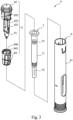
- a medicament delivery device 5 with locking elements is generally cylindrical and comprises a second sub-assembly 6, a first sub-assembly 8 and an intermediate sub-assembly 7 which is arranged between the second sub-assembly 6 and the first sub-assembly 8.
- the present invention will focus on the first sub-assembly 8 and connection between the first sub-assembly 8 and the second sub-assembly 6.
- the second sub-assembly 6 may include a proximal housing 61 which encloses most of the other elements of the second sub-assembly 6, and a protrusion 62 ( Fig. 5A and 13-15 ) inside the second sub-assembly 6.
- the intermediate sub-assembly 7 may include a container 71, a cannula 72 connected to a proximal end of the container 71, and a stopper 73 which is slidably received in the container 71.
- the first sub-assembly 8 may include a plunger rod 81, a main body 82 which slidably receives the plunger rod 81, a biasing member 83 which is accommodated radially between the plunger rod 81 and a guide rod of the main body 82 for biasing the plunger rod 81.
- a coupling member 84 is movably arranged on the main body 82.
- the main body 82 of the first embodiment may comprise a hollow cylinder 821
- a rib 822 radially extends from the cylinder 821 and divides the cylinder 821 into a proximal section and a distal section.
- a radially flexible arm 823 is formed in the proximal section and constitutes a portion of the cylinder 821.
- the flexible arm is configured to be directly connected to the plunger rod 81 to hold the biased plunger rod until the medicament delivery device is assembled and activated.
- a projection 824 extends radially from a proximal end of the proximal section.
- At least one flexible tab 825 longitudinally extends proximally from the distal section.
- the main body 82 has two tabs 825 which are oppositely arranged relative to the longitudinal axis.
- a longitudinal wall 826 radially extends outwards from the cylinder 821 and abuts a distal portion of the tab 825 to radially support tab 825.
- a proximal half of the tab 825 may extend radially outwards from the longitudinal axis of the main body 82, and then radially inwards to form an arch 828.
- a distance between the arch 828 and the central axis is larger than a distance between other portions of the tab 825 and the central axis, and also larger than an outer radius of the coupling member 84 and an inner radius of the proximal housing 61.
- the coupling member 84 of the first embodiment may include a central through-hole through the coupling member 84, a bore 840 concentrically formed at a distal end of the coupling member 84 and having an inner diameter larger than that of the through-hole, a longitudinal groove 841 formed in an inner surface of the through-hole, at least two protrusions 842 extending from an inner surface of the bore 840, and a recess 843 formed between two protrusions 842.
- One of the protrusions 842 may have a ramp-shaped first surface 844 extending in wards from the inner surface of the bore 840 and a second wall-shaped surface 845 extending orthogonally from the inner surface of the bore 840.
- Another (adjacent) protrusion 842 may have two second surfaces 845 radially extending from the inner surface of the bore 840.
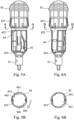
- the projection 824 of the main body 82 passes along the longitudinal groove 841 of the coupling member 84 and then exits from the proximal end of the coupling member 84. In this state, the free end of the tab 825 of the main body 82 is also received within the bore 840 of the coupling member 84.
- the coupling member 84 may be rotated relative to the main body 82. Due to the rotation, the projection 824 of the main body 82 is no longer aligned with the longitudinal groove 841 of the coupling member 84 which prevents the coupling member 84 from detaching from of the main body 82 in the proximal direction. Furthermore, when the coupling member 84 is rotated, the ramp-shaped first surface 844 of the protrusion 842 of the coupling member 84 bends the free end of the tab 825 radially inwards, i.e. towards the longitudinal central axis of the main body 82, whereupon the free end of the tab 825 snaps into the recess 843.
- the tab 825 thereby recovers outwards and the free end of the tab 825 is confined between two second wall-shaped surfaces 845 of two adjacent protrusions 842.
- the coupling member 84 is prevented from rotation relative to the main body 82.
- the tab 825 is a first locking element and the recess 843 is a second locking element. Engagement of the first locking element with the second locking element rotationally locks the coupling member 84 to the main body 82. Since the coupling member 84 is rotationally locked to the main body 82, the flexible arm 823 is confined by the coupling member 84 and the free end of the flexible arm 823 locks the plunger rod 81. Hence, the plunger rod 81 which is biased by the biasing member 83 cannot be released from the main body 82 until it is unlocked by assembly of the first sub-assembly 8 with the second sub-assembly 6.
- the three sub-assemblies 6, 7 and 8 may be assembled to form a final assembly of the medicament delivery device 5.
- the final assembly most of the first sub-assembly 8 is accommodated within the second sub-assembly 6.
- An inner surface of the proximal housing 61 bends the proximal half of the tab 825 inwards to the extent that the free end of the tab 825 is totally released from confinement of the protrusions 842 so that the coupling member 84 is ready to be rotated by other elements of the medicament delivery device 5.
- the distal half of the tab 825 resiliently abuts against the inner surface of the proximal housing 61 to make them tightly fitted.
- the wall 826 supports the distal half of the tab 825 to reinforce a radial tension force between the tab and the inner surface of the proximal housing 61 to prevent the first sub-assembly 8 from detaching from the second sub-assembly 6.
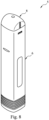
- a medicament delivery device 5 with locking elements of the second embodiment has a square or rectangular cross-section, seen in the longitudinal direction.
- the medicament delivery device 5 comprises a second sub-assembly 6, an intermediate sub-assembly 7 and a first sub-assembly 8.
- the structure of some elements in the second embodiment may be different from those in the first embodiment. However, the function of the elements may be similar or even identical. Hence, the description of the second embodiment will focus on the first sub-assembly 8 and the connection between the first sub-assembly 8 and the second sub-assembly 6.
- the first sub-assembly 8 of the second embodiment comprises a plunger rod 81, a biasing member 83, a biasing member guide 85, a distal cap 86 and a coupling member 84.
- the biasing member guide 85 has a hook 851 at a distal end thereof for passing through and being fixed to a distal end of the coupling member 84.
- the biasing member 83 is accommodated within the biasing member guide 85 for biasing the plunger rod 81.
- the plunger rod 81 is rotatably connected to the distal end of the coupling member 84.
- the coupling member 84 includes at least one multi-sectioned ledge 846 on an outer circumferential surface of the coupling member 84, at least one closed loop 847 extending generally radially outwards from a proximal end of the of outer circumferential surface of the coupling member 84, and at least one cam 848 axially located between the ledge 846 and the closed loop 847, which cam extends radially outwards along the outer circumferential surface of the coupling member 84.
- the coupling member 84 may comprise two ledges 846, two closed loops 847 and two cams 848.
- the cam 848 is ramp-shaped, such that the height of the cam relative to the surface of the coupling member 84 increases along the length of the cam 848.
- the closed loop 847 has a protrusion 842 which is constituted by the first ramp-shaped surface 844 extending from the inner surface of the closed loop 847 and the second wall-shaped surface 845 extending generally radially and orthogonally from the inner surface of the closed loop 847.
- the protrusion 842 and a wall profile of the closed loop 847 define a recess 843.
- the distal cap 86 includes at least one longitudinal tab 825.
- the distal cap 86 may include two tabs 825 which are oppositely arranged relative to the central longitudinal axis.
- a latch 861 extends radially inwards at a distal half of the tab 825.
- a proximal half of the tab 825 may extend outwards and then inwards to form an arch 828.
- a distance between the arch 828 of the proximal half and the central axis is larger than the distance between other portions of the tab 825 and the central axis, and also larger than an outer radius of the coupling member 84 and an inner radius of the proximal housing 61.
- the coupling member 84 When the coupling member 84 is assembled with the distal cap 86, the coupling member 84 is substantially received between two tabs 825 and is rotatably connected to the distal cap 86 by means of the latch 861 abutting against a proximal surface of the ledge 846 of the coupling member 84. Furthermore, the free end of the tab 825 is received within the recess 843 and is thus confined. In this state, the coupling member 84 will be prevented from rotation relative to the biasing member guide 85 and distal cap 86.
- the tab 825 is the first locking element and the recess 843 is the second locking element. Engagement of the first locking element with the second locking element rotationally locks the coupling member 84 to the distal cap 86.
- the plunger rod 81 which is biased by the biasing member 83, cannot be released from the biasing member guide 85 at an inappropriate occasion, such as during transportation and shipment of the first sub-assembly 8.
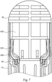
- the distal cap 86 abuts against the inner surface of the proximal housing 61 for a tight fit.
- an inner surface of the proximal housing 61 bends the distal half of the tab 825 inwards to the extent that the free end of the tab 825 is completely disengaged and released from the confinement of the protrusion 842 so that the coupling member 84 is ready to be rotated when the medicament delivery device operated by a user.
- the protrusion 62 of the second sub-assembly 6 is situated on the cylindrical outer surface of the coupling member 84 near the proximal end. In the initial state, there exists a gap 87 between the distal half of the tab 825 and the cam 848 of the coupling member 84. As shown in Fig. 14 , when the second sub-assembly 6 is activated, the protrusion 62 of the second sub-assembly 6 slides along the ledge 846 to rotate the coupling member 84 relative to the distal cap 86.
- the distal half of the tab 825 abuts against the cam 848 because the cam 848 is ramp-shaped around the periphery of the coupling member 84.
- the rotation of the coupling member 84 closes the gap 87 and the cam 848 supports the distal half of the tab 825 so that it does not deform inwards.
- the protrusion 62 of the second sub-assembly 6 longitudinally slides toward the proximal end of the coupling member 84.
- the cam 848 maintains the abutment against the tab 825 because the coupling member 84 is not rotated during this step.
- the features of the distal cap 86 and of the biasing member guide 85 of the second embodiment generally correspond to, or have similar functions as compared to the main body 82 and the plunger rod 81 of the first embodiment.
- the main body 82 of the third embodiment comprises a hollow cylinder 821, and a rib 822 which extends radially from the cylinder 821 and divides the cylinder 821 into a proximal section and a distal section.
- a projection 829 radially extends from a proximal end of the proximal section.
- At least one tab 825 longitudinally extends from the distal section.
- the main body has two tabs 825 which are oppositely arranged relative to the central axis.
- a wall 826 radially extends from the cylinder 821 and connects with the tab 825.
- a shoulder 827 extends proximally from the rib 822.
- a radially flexible arm 823 is formed in the proximal section. The shoulder 827 and the radi ally flexible arm 823 are not longitudinally aligned with each other in the axial direction of the main body 82.
- the coupling member 84 of the third embodiment comprises a central through-hole through the coupling member 84, a curved ledge 846 on an outer surface of the coupling member 84, a recess 843 formed on an inner surface of the coupling member 84, a first notch 8411 formed at a distal end of the coupling member 84, and a second notch 8412 formed at a proximal end of the coupling member 84.
- the first notch 8411 and the second notch 8412 are not aligned with each other in the axial direction of the coupling member 84.
- the projection 829 of the main body 82 is snapped into the recess 843 of the coupling member 84.
- the projection 829 is the first locking element and the recess 843 is the second locking element. Engagement of the first locking element with the second locking element rotationally and axially locks the coupling member 84 to the main body 82. In this state, the distal end of the coupling member 84 does not contact the shoulder 827. Furthermore, the free end of the arm 823 is radi ally locked by an inner surface of the coupling member 84.
- the plunger rod 81 which is biased by the biasing member cannot be released from the main body 82 at an inappropriate occasion, such as during transport ation and shipment of the first sub-assembly 8.
- the three sub-assemblies 6, 7 and 8 may be assembled to form a final assembly of the medicament delivery device 5.
- An inner surface of the proximal housing 61 disengages the projection 829 to the extent that the projection 829 is totally released from the recess 843
- the coupling member 84 is slid, by the second sub-assembly 6, along the cylinder 821 of the main body 82 so that the distal end of the coupling member 84 contacts the shoulder 827 of the main body 82 ( Fig. 18 ).
- the protrusion 62 slides along the ledge 846 to rotate the coupling member 84 to the extent that the first notch 8411 of the coupling member 84 is aligned with the shoulder 827 of the main body 82 and the second notch 8412 is aligned with the arm 823. Subsequently as shown in Figs. 16 and 20 , the protrusion 62 of the second sub-assembly 6 further pushes the ledge 846 to move the coupling member 84 axially sliding along the main body 82 and make
- the shoulder 827 be received within the first notch 8411.
- the free end of the arm 823 of the main body 82 is simultaneously revealed in the second notch 8412. Since, the free end of the arm 823 is no longer locked by the coupling 5 member 84, the arm 823 can spring outwards to release the plunger rod 81 and thus expel medicament in the container 71.
- the medicament delivery device 5 may be alternatively performed with two sub-assemblies.
- the intermediate sub-assembly 7 may be incorporated with the second sub-assembly so that the medicament delivery device 5 merely comprises two sub-assemblies (i.e. a second sub-assembly and a first sub-assembly).
Landscapes
- Health & Medical Sciences (AREA)
- Vascular Medicine (AREA)
- Engineering & Computer Science (AREA)
- Anesthesiology (AREA)
- Biomedical Technology (AREA)
- Heart & Thoracic Surgery (AREA)
- Hematology (AREA)
- Life Sciences & Earth Sciences (AREA)
- Animal Behavior & Ethology (AREA)
- General Health & Medical Sciences (AREA)
- Public Health (AREA)
- Veterinary Medicine (AREA)
- Infusion, Injection, And Reservoir Apparatuses (AREA)
Applications Claiming Priority (3)
| Application Number | Priority Date | Filing Date | Title |
|---|---|---|---|
| SE1550494 | 2015-04-24 | ||
| PCT/EP2016/057243 WO2016169748A1 (fr) | 2015-04-24 | 2016-04-01 | Sous-ensemble de dispositif d'administration de médicament et dispositif d'administration de médicament |
| EP16712939.4A EP3285831B1 (fr) | 2015-04-24 | 2016-04-01 | Sous-ensemble de dispositif d'administration de médicament et dispositif d'administration de médicament |
Related Parent Applications (2)
| Application Number | Title | Priority Date | Filing Date |
|---|---|---|---|
| EP16712939.4A Division EP3285831B1 (fr) | 2015-04-24 | 2016-04-01 | Sous-ensemble de dispositif d'administration de médicament et dispositif d'administration de médicament |
| EP16712939.4A Division-Into EP3285831B1 (fr) | 2015-04-24 | 2016-04-01 | Sous-ensemble de dispositif d'administration de médicament et dispositif d'administration de médicament |
Publications (2)
| Publication Number | Publication Date |
|---|---|
| EP4364767A2 true EP4364767A2 (fr) | 2024-05-08 |
| EP4364767A3 EP4364767A3 (fr) | 2024-08-07 |
Family
ID=55642512
Family Applications (2)
| Application Number | Title | Priority Date | Filing Date |
|---|---|---|---|
| EP24165962.2A Pending EP4364767A3 (fr) | 2015-04-24 | 2016-04-01 | Sous-ensemble d'un dispositif d'administration de médicament et dispositif d'administration de médicament |
| EP16712939.4A Active EP3285831B1 (fr) | 2015-04-24 | 2016-04-01 | Sous-ensemble de dispositif d'administration de médicament et dispositif d'administration de médicament |
Family Applications After (1)
| Application Number | Title | Priority Date | Filing Date |
|---|---|---|---|
| EP16712939.4A Active EP3285831B1 (fr) | 2015-04-24 | 2016-04-01 | Sous-ensemble de dispositif d'administration de médicament et dispositif d'administration de médicament |
Country Status (8)
| Country | Link |
|---|---|
| US (2) | US11690956B2 (fr) |
| EP (2) | EP4364767A3 (fr) |
| JP (1) | JP6531298B2 (fr) |
| KR (2) | KR102039811B1 (fr) |
| CN (2) | CN112870489B (fr) |
| DK (1) | DK3285831T3 (fr) |
| TW (1) | TWI624285B (fr) |
| WO (1) | WO2016169748A1 (fr) |
Families Citing this family (28)
| Publication number | Priority date | Publication date | Assignee | Title |
|---|---|---|---|---|
| DK2552517T3 (en) * | 2010-03-31 | 2017-04-03 | Shl Group Ab | PHARMACEUTICAL DELIVERY DEVICE INCLUDING FEEDBACK SIGNALS |
| WO2016169756A1 (fr) * | 2015-04-24 | 2016-10-27 | Carebay Europe Ltd | Mécanisme d'entraînement pour un auto-injecteur |
| DK3285831T3 (da) * | 2015-04-24 | 2024-05-27 | Shl Medical Ag | Underenhed af en medikamenttilførselsanordning og en medikamenttilførselsanordning |
| TW201707738A (zh) | 2015-06-03 | 2017-03-01 | 賽諾菲阿凡提斯德意志有限公司 | 注射器支架及自動注射器(二) |
| USD810282S1 (en) * | 2015-10-19 | 2018-02-13 | Carebay Europe Ltd | Medical injector |
| US10967128B2 (en) | 2016-07-14 | 2021-04-06 | Shl Medical Ag | Administration mechanism for a medicament delivery device |
| WO2018206583A1 (fr) | 2017-05-09 | 2018-11-15 | Shl Medical Ag | Ensemble de verrouillage de transport, et dispositif d'administration de médicament comprenant l'ensemble de verrouillage de transport |
| WO2019011689A1 (fr) * | 2017-07-12 | 2019-01-17 | Shl Medical Ag | Ensemble de transport pour dispositif d'administration de médicament et dispositif d'administration de médicament le comprenant |
| JP1629612S (fr) * | 2017-10-25 | 2019-04-15 | ||
| CN111936183B (zh) * | 2017-11-21 | 2023-03-03 | 赛诺菲 | 用于药物递送装置的驱动子组件 |
| AU2019236105B2 (en) | 2018-03-14 | 2025-07-31 | Boehringer Ingelheim International Gmbh | Use of anti-IL-36R antibodies for treatment of generalized pustular psoriasis |
| WO2019177883A2 (fr) | 2018-03-14 | 2019-09-19 | Boehringer Ingelheim International Gmbh | Utilisation d'anticorps anti-il-36 r pour le traitement d'une maladie intestinale inflammatoire |
| USD908868S1 (en) | 2018-05-16 | 2021-01-26 | Sanofi | Injection device |
| USD866751S1 (en) * | 2018-05-22 | 2019-11-12 | Sanofi | Injection device |
| AU2019359801B2 (en) * | 2018-10-15 | 2025-01-02 | Amgen Inc. | Platform assembly process for drug delivery device |
| TW202037604A (zh) | 2018-12-27 | 2020-10-16 | 德商百靈佳殷格翰國際股份有限公司 | 治療掌蹠膿疱症之抗il-36r抗體 |
| EP4054680B1 (fr) * | 2019-11-08 | 2026-04-15 | SHL Medical AG | Rotateur tubulaire |
| WO2021170263A1 (fr) | 2020-02-24 | 2021-09-02 | Shl Medical Ag | Sous-ensemble pour dispositif d'administration de médicament et dispositif d'administration de médicament comprenant le sous-ensemble |
| US12569621B2 (en) | 2020-04-07 | 2026-03-10 | Shl Medical Ag | Sub-assembly for medicament delivery device, and medicament delivery device comprising the sub-assembly |
| US20220010022A1 (en) | 2020-05-19 | 2022-01-13 | Boehringer Ingelheim International Gmbh | Anti-il-36r antibodies for the treatment of atopic dermatitis |
| EP4267221A1 (fr) * | 2020-12-24 | 2023-11-01 | SHL Medical AG | Dispositif d?administration de médicament |
| MX2023010289A (es) | 2021-03-04 | 2023-09-11 | Boehringer Ingelheim Int | Uso de anticuerpos anti-il-36r en el tratamiento de la psoriasis pustulosa generalizada. |
| EP4433123A1 (fr) * | 2021-11-17 | 2024-09-25 | SHL Medical AG | Composants et sous-ensembles pour dispositifs d'administration de médicament |
| CN118843490A (zh) * | 2022-03-22 | 2024-10-25 | 艾斯曲尔医疗公司 | 用于药剂递送装置的子组件和对应的装配方法 |
| KR20260025132A (ko) | 2023-06-09 | 2026-02-23 | 베링거 인겔하임 인터내셔날 게엠베하 | 전신 농포성 건선(gpp)의 치료 및 예방 방법 |
| EP4552673A1 (fr) * | 2023-11-07 | 2025-05-14 | Ypsomed AG | Dispositif d'injection à quantité réduite de pièces |
| US12427266B1 (en) | 2024-03-28 | 2025-09-30 | Genzyme Corporation | Needle shroud latch for injection devices |
| US12502482B2 (en) * | 2024-03-28 | 2025-12-23 | Genzyme Corporation | Collar cam lock for injection devices |
Citations (1)
| Publication number | Priority date | Publication date | Assignee | Title |
|---|---|---|---|---|
| WO2011123024A1 (fr) | 2010-03-31 | 2011-10-06 | Shl Group Ab | Dispositif d'administration de médicament comprenant un moyen de signalisation de retour d'informations |
Family Cites Families (34)
| Publication number | Priority date | Publication date | Assignee | Title |
|---|---|---|---|---|
| GB9111600D0 (en) * | 1991-05-30 | 1991-07-24 | Owen Mumford Ltd | Improvements relating to injection devices |
| DE29801168U1 (de) * | 1998-01-24 | 1999-08-12 | Medico Dev Investment Co | Injektionsgerät |
| US7887506B1 (en) * | 1999-11-23 | 2011-02-15 | Pulse Needlefree Systems, Inc. | Safety mechanism to prevent accidental patient injection and methods of same |
| US7699816B2 (en) * | 2002-10-15 | 2010-04-20 | Tecpharma Licensing Ag | Injection device with priming stroke |
| GB0224505D0 (en) | 2002-10-22 | 2002-11-27 | Medical House The Plc | Needles injection device |
| TW566299U (en) | 2003-04-07 | 2003-12-11 | Wuz Ta Ind Co Ltd | Tool head fixer |
| TWI498137B (zh) * | 2006-06-30 | 2015-09-01 | Abbvie Biotechnology Ltd | 自動注射裝置 |
| DE102007008369A1 (de) | 2007-02-16 | 2008-08-21 | Lts Lohmann Therapie-Systeme Ag | Einweginjektor mit mindestens einem zentralen Zugstab |
| CN101641125B (zh) * | 2007-03-09 | 2013-06-19 | 伊莱利利公司 | 用于自动注射设备的延迟机构 |
| GB2463034B (en) | 2008-08-28 | 2012-11-07 | Owen Mumford Ltd | Autoinjection devices |
| ES2778729T3 (es) * | 2008-11-07 | 2020-08-11 | Becton Dickinson Co | Alojamiento de jeringuilla para facilitar la inyección de medicamento |
| AU2010226442A1 (en) | 2009-03-20 | 2011-10-13 | Antares Pharma, Inc. | Hazardous agent injection system |
| JP5805111B2 (ja) * | 2010-02-18 | 2015-11-04 | サノフィ−アベンティス・ドイチュラント・ゲゼルシャフト・ミット・ベシュレンクテル・ハフツング | トーションばねを備えた自動注射器 |
| WO2011153529A2 (fr) * | 2010-06-04 | 2011-12-08 | University Of South Florida | Instrument laparoscopique sans incision |
| US8414481B2 (en) * | 2010-06-24 | 2013-04-09 | General Electric Company | Laryngoscope |
| EP2489387A1 (fr) * | 2011-02-18 | 2012-08-22 | Sanofi-Aventis Deutschland GmbH | Auto-injecteur |
| EP2699289A1 (fr) | 2011-04-21 | 2014-02-26 | Sanofi-Aventis Deutschland GmbH | Module de médicaments à élément de verrouillage |
| CH705345A2 (de) * | 2011-08-04 | 2013-02-15 | Tecpharma Licensing Ag | Injektionsvorrichtung mit Nadelschutzeinrichtung. |
| RU2626132C2 (ru) * | 2011-09-09 | 2017-07-21 | Мерк Патент Гмбх | Автоматический инъектор для инъекции адреналина |
| AU2012341113B2 (en) * | 2011-11-25 | 2015-04-09 | Shl Group Ab | Medicament delivery device |
| US9241731B2 (en) * | 2012-04-09 | 2016-01-26 | Ethicon Endo-Surgery, Inc. | Rotatable electrical connection for ultrasonic surgical instruments |
| US9364610B2 (en) * | 2012-05-07 | 2016-06-14 | Antares Pharma, Inc. | Injection device with cammed ram assembly |
| WO2014005807A1 (fr) * | 2012-07-06 | 2014-01-09 | Carebay Europe Ltd | Dispositif d'administration de médicament |
| JP6140829B2 (ja) * | 2012-10-05 | 2017-05-31 | ケアベイ・ヨーロッパ・リミテッドCarebay Europe Limited | 薬剤送達装置 |
| LT2908887T (lt) * | 2012-10-19 | 2018-08-10 | Eli Lilly And Company | Automatinis įšvirkštimo įrenginys su paleidimo konstrukcija |
| US8591463B1 (en) * | 2013-03-08 | 2013-11-26 | Teva Pharmaceutical Industries Ltd. | Re-useable injector device for syringe |
| JP6132969B2 (ja) * | 2013-03-14 | 2017-05-24 | イーライ リリー アンド カンパニー | 自動注射装置のためのトリガーアセンブリー |
| US10322240B2 (en) | 2013-03-25 | 2019-06-18 | Shl Medical Ag | Power pack lock |
| WO2014166919A1 (fr) * | 2013-04-10 | 2014-10-16 | Sanofi | Mécanisme d'entraînement pour dispositif d'administration de médicament |
| CN105517600A (zh) * | 2013-08-08 | 2016-04-20 | 卡贝欧洲有限公司 | 动力单元 |
| KR101780613B1 (ko) * | 2013-08-29 | 2017-09-21 | 케어베이 유럽 리미티드 | 약물 전달 장치 |
| WO2015151693A1 (fr) * | 2014-03-31 | 2015-10-08 | テルモ株式会社 | Seringue préremplie |
| JP2017527405A (ja) * | 2014-09-18 | 2017-09-21 | ノボ・ノルデイスク・エー/エス | ピストンドライバ遠位特徴を備えた薬剤送達装置 |
| DK3285831T3 (da) * | 2015-04-24 | 2024-05-27 | Shl Medical Ag | Underenhed af en medikamenttilførselsanordning og en medikamenttilførselsanordning |
-
2016
- 2016-04-01 DK DK16712939.4T patent/DK3285831T3/da active
- 2016-04-01 WO PCT/EP2016/057243 patent/WO2016169748A1/fr not_active Ceased
- 2016-04-01 EP EP24165962.2A patent/EP4364767A3/fr active Pending
- 2016-04-01 KR KR1020177033850A patent/KR102039811B1/ko active Active
- 2016-04-01 KR KR1020197031614A patent/KR102375765B1/ko active Active
- 2016-04-01 CN CN202110052987.1A patent/CN112870489B/zh active Active
- 2016-04-01 US US15/566,316 patent/US11690956B2/en active Active
- 2016-04-01 EP EP16712939.4A patent/EP3285831B1/fr active Active
- 2016-04-01 CN CN201680029359.9A patent/CN107660155B/zh active Active
- 2016-04-01 JP JP2017555537A patent/JP6531298B2/ja active Active
- 2016-04-12 TW TW105111381A patent/TWI624285B/zh active
-
2023
- 2023-05-17 US US18/198,692 patent/US20230285674A1/en active Pending
Patent Citations (1)
| Publication number | Priority date | Publication date | Assignee | Title |
|---|---|---|---|---|
| WO2011123024A1 (fr) | 2010-03-31 | 2011-10-06 | Shl Group Ab | Dispositif d'administration de médicament comprenant un moyen de signalisation de retour d'informations |
Also Published As
| Publication number | Publication date |
|---|---|
| EP3285831A1 (fr) | 2018-02-28 |
| KR20170139635A (ko) | 2017-12-19 |
| WO2016169748A1 (fr) | 2016-10-27 |
| US11690956B2 (en) | 2023-07-04 |
| KR102375765B1 (ko) | 2022-03-17 |
| US20230285674A1 (en) | 2023-09-14 |
| EP4364767A3 (fr) | 2024-08-07 |
| US20180104414A1 (en) | 2018-04-19 |
| KR102039811B1 (ko) | 2019-11-01 |
| JP6531298B2 (ja) | 2019-06-19 |
| EP3285831B1 (fr) | 2024-05-01 |
| CN112870489A (zh) | 2021-06-01 |
| CN107660155B (zh) | 2021-02-02 |
| JP2018513751A (ja) | 2018-05-31 |
| TW201709939A (zh) | 2017-03-16 |
| CN107660155A (zh) | 2018-02-02 |
| DK3285831T3 (da) | 2024-05-27 |
| CN112870489B (zh) | 2022-12-06 |
| TWI624285B (zh) | 2018-05-21 |
| KR20190123810A (ko) | 2019-11-01 |
Similar Documents
| Publication | Publication Date | Title |
|---|---|---|
| US20230285674A1 (en) | Sub-assembly of a medicament delivery device and a medicament delivery device | |
| CN110753563B (zh) | 用于药剂输送装置的给药组件及包括该给药组件的药剂输送装置 | |
| US11992658B2 (en) | Injection device for delivering a defined number of equal doses of a fluid substance | |
| TWI538708B (zh) | 蓋組合件 | |
| TWI630936B (zh) | 驅動機構和藥物輸送裝置 | |
| JP6970293B2 (ja) | 薬剤送達デバイスのための投与組立体及びこの投与組立体を備える薬剤送達デバイス | |
| CN102573963A (zh) | 剂量重置机构 | |
| CN110769879A (zh) | 用于药剂输送装置的运输组件和包括该运输组件的药剂输送装置 | |
| CN109475701B (zh) | 用于药剂输送装置的药剂容器组件 | |
| CN118767253A (zh) | 用于将产品自动注射到注射部位中的自动注射装置 | |
| RU2754801C2 (ru) | Муфта в сборе с блокирующей системой для медицинского устройства для инъекций | |
| US10857285B2 (en) | Support structure | |
| JP2019516513A (ja) | 作動機構 | |
| JP6886146B2 (ja) | 注射器 | |
| US12569621B2 (en) | Sub-assembly for medicament delivery device, and medicament delivery device comprising the sub-assembly | |
| CN105848697A (zh) | 药剂输送装置和其组装方法 | |
| JP2024537280A (ja) | 薬物送達装置 | |
| PL237295B1 (pl) | Mechanizm sterujący aplikatora i sposób jego montażu |
Legal Events
| Date | Code | Title | Description |
|---|---|---|---|
| PUAI | Public reference made under article 153(3) epc to a published international application that has entered the european phase |
Free format text: ORIGINAL CODE: 0009012 |
|
| STAA | Information on the status of an ep patent application or granted ep patent |
Free format text: STATUS: THE APPLICATION HAS BEEN PUBLISHED |
|
| AC | Divisional application: reference to earlier application |
Ref document number: 3285831 Country of ref document: EP Kind code of ref document: P |
|
| AK | Designated contracting states |
Kind code of ref document: A2 Designated state(s): AL AT BE BG CH CY CZ DE DK EE ES FI FR GB GR HR HU IE IS IT LI LT LU LV MC MK MT NL NO PL PT RO RS SE SI SK SM TR |
|
| PUAL | Search report despatched |
Free format text: ORIGINAL CODE: 0009013 |
|
| AK | Designated contracting states |
Kind code of ref document: A3 Designated state(s): AL AT BE BG CH CY CZ DE DK EE ES FI FR GB GR HR HU IE IS IT LI LT LU LV MC MK MT NL NO PL PT RO RS SE SI SK SM TR |
|
| RIC1 | Information provided on ipc code assigned before grant |
Ipc: A61M 5/20 20060101AFI20240703BHEP |
|
| STAA | Information on the status of an ep patent application or granted ep patent |
Free format text: STATUS: REQUEST FOR EXAMINATION WAS MADE |
|
| 17P | Request for examination filed |
Effective date: 20250206 |
|
| STAA | Information on the status of an ep patent application or granted ep patent |
Free format text: STATUS: EXAMINATION IS IN PROGRESS |