EP4364863A1 - Vorrichtung zum sortieren von hergestellten artikeln - Google Patents
Vorrichtung zum sortieren von hergestellten artikeln Download PDFInfo
- Publication number
- EP4364863A1 EP4364863A1 EP23206399.0A EP23206399A EP4364863A1 EP 4364863 A1 EP4364863 A1 EP 4364863A1 EP 23206399 A EP23206399 A EP 23206399A EP 4364863 A1 EP4364863 A1 EP 4364863A1
- Authority
- EP
- European Patent Office
- Prior art keywords
- manufactured articles
- appliance
- fact
- arrival
- stacking
- Prior art date
- Legal status (The legal status is an assumption and is not a legal conclusion. Google has not performed a legal analysis and makes no representation as to the accuracy of the status listed.)
- Granted
Links
Images



Classifications
-
- B—PERFORMING OPERATIONS; TRANSPORTING
- B07—SEPARATING SOLIDS FROM SOLIDS; SORTING
- B07C—POSTAL SORTING; SORTING INDIVIDUAL ARTICLES, OR BULK MATERIAL FIT TO BE SORTED PIECE-MEAL, e.g. BY PICKING
- B07C5/00—Sorting according to a characteristic or feature of the articles or material being sorted, e.g. by control effected by devices which detect or measure such characteristic or feature; Sorting by manually actuated devices, e.g. switches
- B07C5/36—Sorting apparatus characterised by the means used for distribution
-
- B—PERFORMING OPERATIONS; TRANSPORTING
- B65—CONVEYING; PACKING; STORING; HANDLING THIN OR FILAMENTARY MATERIAL
- B65G—TRANSPORT OR STORAGE DEVICES, e.g. CONVEYORS FOR LOADING OR TIPPING, SHOP CONVEYOR SYSTEMS OR PNEUMATIC TUBE CONVEYORS
- B65G57/00—Stacking of articles
- B65G57/02—Stacking of articles by adding to the top of the stack
- B65G57/03—Stacking of articles by adding to the top of the stack from above
- B65G57/04—Stacking of articles by adding to the top of the stack from above by suction or magnetic devices
-
- B—PERFORMING OPERATIONS; TRANSPORTING
- B07—SEPARATING SOLIDS FROM SOLIDS; SORTING
- B07C—POSTAL SORTING; SORTING INDIVIDUAL ARTICLES, OR BULK MATERIAL FIT TO BE SORTED PIECE-MEAL, e.g. BY PICKING
- B07C2501/00—Sorting according to a characteristic or feature of the articles or material to be sorted
- B07C2501/0063—Using robots
Definitions
- the present invention relates to an appliance for sorting manufactured articles.
- such appliances are generally set up in packaging areas for manufactured articles of the type of tiles, slabs or the like, where the same access, one in line with the other, by running along dedicated arrival lines and output lines.
- known appliances comprise sorting means which are arranged at the arrival line and are configured to grasp the manufactured articles being transported along the latter (e.g., by means of grippers or suction cup devices) and to transfer them, depending on one or more of the above predetermined characteristics, to respective temporary storage stations located laterally to the conveyor line.
- the sorting means operate a selective collection of the manufactured articles and, by placing those of them sharing similar predetermined characteristics in the same storage stations, effectively determines their sorting.
- the manufactured articles thus separated are gradually stacked on top of each other in the various storage stations to form stacks of structurally and/or aesthetically similar products intended for packaging.
- EP-A-0077304 and SE-A-2030327 describe appliances for sorting manufactured articles of known type.
- the main aim of the present invention is to devise an appliance for sorting manufactured articles provided with a rational layout which allows, in particular, easy connection with the machines located upstream and downstream thereof.
- the object of the present invention is to devise an appliance for sorting manufactured articles distinguished by small overall dimensions and, therefore, easy installation in both large spaces and confined spaces, resulting in savings of time and economic resources compared to the aforementioned prior art.
- Another object of the present invention is to devise an appliance for sorting manufactured articles with high production output.
- a further object of the present invention is to devise an appliance for sorting manufactured articles with accurate and precise operation which allows lowering the risk of damaging and breaking the manufactured articles.
- Not the least object of the present invention is to devise an appliance for sorting manufactured articles in which the operations of replacement of its components can be done easily and cost-effectively.
- Another object of the present invention is to devise an appliance for sorting manufactured articles which allows the aforementioned drawbacks of the prior art to be overcome within the framework of a simple, rational, easy and effective to use and cost-effective solution.
- reference numeral 1 globally denotes an appliance for sorting manufactured articles.
- the term "manufactured articles” preferably relates to slab-shaped semi-finished products made of ceramic material, particularly of the type of ceramic tiles.
- the appliance 1 for sorting manufactured articles comprises:
- arrival line 3 and the output line 6 it is good to say, first of all, that they preferably consist of at least one (preferably two) motorized conveyor belts on which the manufactured articles M to be sorted and the sorted manufactured articles M are conveyed, respectively.
- the arrival line 3 defines a direction of arrival A1, the latter being arranged substantially horizontally.
- the direction of away movement A2 defined by the output line 6 is also arranged substantially horizontally.
- the direction of arrival A1 and the direction of away movement A2 are substantially parallel to each other.
- the output line 6 can be conveniently connected to one or more stations where the sorted manufactured articles M can be directed, e.g. to one or more stations for packaging the same.
- the arrival line 3 and the output line 6 are substantially aligned vertically with each other.
- the vertical alignment of the arrival line 3 to the output line 6 allows the layout of the appliance 1 to be optimized and, as a direct consequence, allows to be more easily connected to the machines located upstream and downstream thereof.
- the sorting assembly 5 preferably comprises:
- the displacement of the gripping elements 7 between the gripping position and the release position occurs along a horizontal direction of transfer T.
- the direction of transfer T is transverse to the direction of arrival A1 and to the direction of away movement A2.
- the direction of transfer T is substantially orthogonal to the direction of arrival A1 and to the direction of away movement A2.
- the gripping elements 7 are vertically aligned with the arrival line 3 and, therefore, are able to grasp the manufactured articles M to be sorted carried thereon.
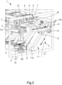
- the gripping elements 7 are moved away from the arrival line 3 and placed where the sorting assembly 5 is located on which they release the previously grasped manufactured articles M ( Figure 2 ).
- the gripping elements 7 may have only one degree of freedom corresponding to the possibility of moving along the aforementioned direction of transfer T.
- the sorting assembly 5 in such a way that the gripping elements 7 are also allowed to move along a substantially vertical direction.
- the gripping elements 7 have two degrees of freedom corresponding to the possibility of the same to move along two mutually orthogonal directions.
- the gripping elements 7 can be moved either horizontally along the direction of transfer T or vertically along an auxiliary direction Y, e.g., to promote the grasping and storing of the manufactured articles M on the arrival line 3 and on the receiving assembly 4, respectively (see Figure 2 , where the different height at which the gripping elements 7 are positioned can be seen, and Figure 3 ).
- the alternating movement of the gripping elements 7 results in that, as one of them moves away from the arrival line 3 (and, thus, moves close to the receiving assembly 4), the other of them moves close to the arrival line 3 (and, thus, moves away from the receiving assembly 4).
- gripping elements 7 it is possible to add that they can work by suction and be, in this sense, of the type of suction cups or similar devices. The possibility cannot however be ruled out of providing gripping elements 7 of different types, e.g. of the type of mechanical grippers or of other types still known to the branch technician.
- the transfer means 8 comprise at least two rails 9 arranged along the direction of transfer T.
- each gripping element 7 is associated with a respective rail 9 in a sliding manner between the gripping position and the release position.
- the sorting assembly 5 comprises at least one holding crossbeam 10 associated with the base frame 2 and with which the rails 9 are associated.
- the rails 9 and, with them, the respective gripping elements 7 are placed on the holding crossbeam 10 in opposite positions to each other.
- the holding crossbeam 10 also extends substantially parallel to the direction of transfer T.
- the receiving assembly 4 comprises:
- the stacking structure 11 has a substantially elongated conformation.
- the stacking structure 11 defines a respective first guide 11a developing along the direction of stacking I and wherein the supporting means 12 slide between the raised position and the lowered position.
- stacking structure 11 is developed, from top to bottom, close to the arrival line 3 and to the output line 6.
- the direction of stacking I is transverse to the lying plane P.
- the arrival line 3 is arranged substantially at the same height occupied by the supporting means 12 in the raised position.
- the output line 6 is arranged substantially at the same height occupied by the holding element 14 in the lowered position.
- the supporting means 12 move, along the direction of stacking I, between two boundary heights; one, wherein the supporting means 12 are aligned with the arrival line 3 (i.e., the raised position), and the other, wherein the supporting means 12 are aligned with the output line 6 (i.e., the lowered position). More particularly, the lowered position and the raised position correspond to the end-of-stroke positions of the supporting means 12 along the direction of stacking I.
- the supporting means 12 are devoid of the manufactured articles M to support.
- the supporting means 12 As more and more manufactured articles M are stacked on the supporting means 12, the latter are progressively lowered with respect to the raised position.
- the lowering of the supporting means 12 is such that the last manufactured article M to be added to the stack is always released at the same height regardless of the height of the stack itself (compare Figures 3 and 4 in this regard).
- the latter are further lowered along the direction of stacking I and brought, thus, to the lowered position.
- the desired number of manufactured articles M to be stacked on the supporting means 12 is reached when the latter are arranged at a height comprised between the arrival line 3 and the output line 6.
- the manufactured articles M taken from the arrival line 3 can be arranged on the supporting means themselves in a totally safe manner, i.e., preventing their detachment from the gripping elements 7 from causing them to be damaged or broken due to falling onto the stacks of manufactured articles M that have already been sorted.
- the manufactured articles M thus sorted create stacks of structurally and/or aesthetically similar products that can be sent for packaging.
- the supporting base 13 has an elongated conformation and develops in a direction substantially parallel to the direction of transfer T.
- the supporting base 13 and the holding crossbeam 10 are arranged parallel to each other.
- the supporting base 13 is inserted into the first guide 11a and is therefore sliding, within the latter, between the raised position and the lowered position.
- the gripping elements 7 are moved horizontally between a position of vertical alignment with the arrival line 3 (i.e., the gripping position) and a position of vertical alignment with the holding element 14 (i.e., the release position).
- the holding element 14 is movable, with respect to the supporting base 13, along a substantially horizontal direction of work L.
- the holding element 14 has two degrees of freedom corresponding to the ability to move along two directions transverse to each other, one corresponding to the direction of stacking I and the other corresponding to the direction of work L.
- the direction of work L is substantially parallel to the direction of transfer T.
- the rails 9 on the holding crossbeam 10 are arranged substantially parallel to the direction of work L.
- the supporting base 13 comprises at least a respective second guide 13a developed parallel to the direction of work L and with which the holding element 14 is associated in a sliding manner.
- the holding element 14 is adapted to displace, along the direction of work L and, therefore, along the second guide 13a, away from the output line 6 during the displacement of the supporting base 13 along the direction of stacking I from the raised position towards the lowered position. Specifically, at the raised position the holding element 14 is arranged in an extended position wherein it is at greater distance from the stacking structure 11 along the direction of work L.
- the holding element 14 is moved progressively from the aforementioned extended position to a retracted position wherein it is at a shorter distance from the stacking structure 11 along the direction of work L.
- the holding element 14 reaches the above retracted position when it is in the intermediate position, that is, in the position, comprised between the raised position and the lowered position, wherein the holding element 14 is located when the last manufactured article M of the stack is stored thereon.
- the fact that the holding element 14 recedes close to the stacking structure 11 as more and more manufactured articles M are stacked on the supporting means 12 allows the holding element 14 to reduce its height while keeping its horizontal position substantially unchanged.
- this expedient allows the manufactured articles M to be stacked on the holding element 14 in such a way that they make vertical stacks, which benefits the safety and efficiency of their sorting.
- the holding element 14 is movable along the direction of work L to at least one storage position of the manufactured articles M, wherein it protrudes from the supporting base 13 (see, in this regard, Figure 6 ). Specifically, the storage position is placed at the same height as the lowered position.
- the holding element 14 can be moved along the direction of work L so as to reach the aforementioned storage position.
- the holding element 14 in the storage position overlaps at least partly with the output line 6, thus allowing the release on the latter of the stack of manufactured articles M held by it and the consequent away movement of the stack itself.
- the output line 6 comprises at least one interrupted stretch 15 arranged at the receiving assembly 4 and adapted to allow the holding element 14 to be inserted into the output line itself (see Figures 2 and 6 ).
- arranging the holding element 14 in the storage position implies that the same crosses the interrupted stretch 15 and, therefore, to insert itself into the output line 6, thus allowing the stack of manufactured articles M held by it to be unloaded onto the output line and to be conveyed, e.g., towards the aforementioned packaging station.
- the appliance 1 preferably comprises a plurality of sorting assemblies 5 and a plurality of receiving assemblies 4 arranged in succession to each other along the direction of arrival A1.
- the appliance 1 also comprises a plurality of interrupted stretches 15, each arranged at a respective receiving assembly 4.
- the sorting assemblies 5 are thus arranged, parallel to each other, at respective stretches of the arrival line 3, and each sorting assembly 5 is operationally connected to a respective receiving assembly 4 arranged at the same stretch.
- the sorting assemblies 5 are aligned with each other laterally to the arrival line 3.
- each of the sorting assemblies 5 picks up the manufactured articles M carried on the arrival line 3 and transfers them to the respective receiving assembly 4 (the one, that is, associated with the same stretch of the arrival line 3) depending on whether or not they have a special predetermined characteristic related to, e.g., aesthetic finish, color, shape, weight, size or other sorting parameters still.
- Each manufactured article M is substantially grasped by a special sorting assembly 5 and stored in the respective receiving assembly 4 depending on its own technical and/or aesthetic peculiarities, so that in each receiving assembly 4 come manufactured articles M sharing similar predetermined characteristics.
- the receiving assembly of the appliance according to the invention allows, due to its special structure and peculiar operation, to effectively and safely stack the manufactured articles stored therein by the sorting assembly, i.e., averting the risk of damage and/or breakage of one or more of the latter.
- the fact that the stacking direction of the manufactured articles is arranged obliquely makes it possible to achieve the aforementioned advantages by reducing, the size of the stacking structure being equal, the overall dimensions of the appliance even more drastically.
Landscapes
- Engineering & Computer Science (AREA)
- Mechanical Engineering (AREA)
- Sheets, Magazines, And Separation Thereof (AREA)
- Sorting Of Articles (AREA)
- Stacking Of Articles And Auxiliary Devices (AREA)
Applications Claiming Priority (1)
| Application Number | Priority Date | Filing Date | Title |
|---|---|---|---|
| IT102022000022542A IT202200022542A1 (it) | 2022-11-03 | 2022-11-03 | Apparecchiatura per lo smistamento di manufatti |
Publications (2)
| Publication Number | Publication Date |
|---|---|
| EP4364863A1 true EP4364863A1 (de) | 2024-05-08 |
| EP4364863B1 EP4364863B1 (de) | 2026-01-28 |
Family
ID=84943877
Family Applications (1)
| Application Number | Title | Priority Date | Filing Date |
|---|---|---|---|
| EP23206399.0A Active EP4364863B1 (de) | 2022-11-03 | 2023-10-27 | Vorrichtung zum sortieren von hergestellten artikeln |
Country Status (2)
| Country | Link |
|---|---|
| EP (1) | EP4364863B1 (de) |
| IT (1) | IT202200022542A1 (de) |
Cited By (1)
| Publication number | Priority date | Publication date | Assignee | Title |
|---|---|---|---|---|
| EP4732965A1 (de) * | 2024-10-28 | 2026-04-29 | Siti - B&T Group S.p.A. | Vorrichtung zum sortieren von hergestellten artikeln |
Citations (3)
| Publication number | Priority date | Publication date | Assignee | Title |
|---|---|---|---|---|
| EP0077304A2 (de) | 1981-08-05 | 1983-04-20 | GOMES S.r.l. | Sortier-, Verteil- und Stapelmaschine für keramische Produkte und Fliesen |
| US5427252A (en) * | 1991-08-28 | 1995-06-27 | Westinghouse Electric Corporation | Automated system and method for sorting and stacking reusable cartons |
| SE2030327A1 (en) | 2020-10-28 | 2021-12-21 | Zenrobotics Oy | Waste Sorting Robot with gripper that releases waste object at a throw position |
-
2022
- 2022-11-03 IT IT102022000022542A patent/IT202200022542A1/it unknown
-
2023
- 2023-10-27 EP EP23206399.0A patent/EP4364863B1/de active Active
Patent Citations (3)
| Publication number | Priority date | Publication date | Assignee | Title |
|---|---|---|---|---|
| EP0077304A2 (de) | 1981-08-05 | 1983-04-20 | GOMES S.r.l. | Sortier-, Verteil- und Stapelmaschine für keramische Produkte und Fliesen |
| US5427252A (en) * | 1991-08-28 | 1995-06-27 | Westinghouse Electric Corporation | Automated system and method for sorting and stacking reusable cartons |
| SE2030327A1 (en) | 2020-10-28 | 2021-12-21 | Zenrobotics Oy | Waste Sorting Robot with gripper that releases waste object at a throw position |
Cited By (1)
| Publication number | Priority date | Publication date | Assignee | Title |
|---|---|---|---|---|
| EP4732965A1 (de) * | 2024-10-28 | 2026-04-29 | Siti - B&T Group S.p.A. | Vorrichtung zum sortieren von hergestellten artikeln |
Also Published As
| Publication number | Publication date |
|---|---|
| IT202200022542A1 (it) | 2024-05-03 |
| EP4364863B1 (de) | 2026-01-28 |
Similar Documents
| Publication | Publication Date | Title |
|---|---|---|
| CN110027900B (zh) | 生产流水线及送料装置 | |
| CN104854006B (zh) | 用于分拣物品的设备 | |
| WO2019097442A1 (en) | Gripper for the grip of loads | |
| CN212739692U (zh) | 一种用于料盘的自动上下料装置 | |
| CN104085694A (zh) | 一种自动错位下料机构 | |
| CN109110511A (zh) | 一种托盘自动拆码垛机构及自动拆码垛方法 | |
| CN108750689B (zh) | 码垛设备及码垛方法 | |
| EP4364863B1 (de) | Vorrichtung zum sortieren von hergestellten artikeln | |
| CN208603372U (zh) | 一种多仓位自动上料堆垛机系统 | |
| EP3334657B1 (de) | Umreifungsvorrichtung für packungen und umreifungsverfahren | |
| US4121723A (en) | Installation for stacking sheet metal plates into packets and for supplying the packets to a binding station | |
| RU2729845C2 (ru) | Установка для сортировки изделий | |
| KR101003722B1 (ko) | 트레이 반송 시스템 | |
| CN112061716A (zh) | 一种烧结砖人机协作式卸砖编组方法及装置 | |
| CN105819017B (zh) | 一种包装机 | |
| EP4732965A1 (de) | Vorrichtung zum sortieren von hergestellten artikeln | |
| CN118359008A (zh) | 一种柜内机拆垛机构 | |
| CN211077705U (zh) | 进料搬运机 | |
| CN210735467U (zh) | 一种玻璃清洗线下料机 | |
| EP4600180B1 (de) | Automatisches system zum speichern und handhaben von zu verarbeitenden artikelgruppen | |
| CN112607432A (zh) | 收杯架 | |
| CN222612364U (zh) | 一种柜内机拆垛机构 | |
| CN212862037U (zh) | 一种护工手套包装用运输设备 | |
| CN206297785U (zh) | 玻璃管码垛机 | |
| CN216154995U (zh) | 一种料箱码分机设备 |
Legal Events
| Date | Code | Title | Description |
|---|---|---|---|
| PUAI | Public reference made under article 153(3) epc to a published international application that has entered the european phase |
Free format text: ORIGINAL CODE: 0009012 |
|
| STAA | Information on the status of an ep patent application or granted ep patent |
Free format text: STATUS: THE APPLICATION HAS BEEN PUBLISHED |
|
| AK | Designated contracting states |
Kind code of ref document: A1 Designated state(s): AL AT BE BG CH CY CZ DE DK EE ES FI FR GB GR HR HU IE IS IT LI LT LU LV MC ME MK MT NL NO PL PT RO RS SE SI SK SM TR |
|
| STAA | Information on the status of an ep patent application or granted ep patent |
Free format text: STATUS: REQUEST FOR EXAMINATION WAS MADE |
|
| 17P | Request for examination filed |
Effective date: 20241108 |
|
| RBV | Designated contracting states (corrected) |
Designated state(s): AL AT BE BG CH CY CZ DE DK EE ES FI FR GB GR HR HU IE IS IT LI LT LU LV MC ME MK MT NL NO PL PT RO RS SE SI SK SM TR |
|
| TPAC | Observations filed by third parties |
Free format text: ORIGINAL CODE: EPIDOSNTIPA |
|
| GRAP | Despatch of communication of intention to grant a patent |
Free format text: ORIGINAL CODE: EPIDOSNIGR1 |
|
| STAA | Information on the status of an ep patent application or granted ep patent |
Free format text: STATUS: GRANT OF PATENT IS INTENDED |
|
| INTG | Intention to grant announced |
Effective date: 20250902 |
|
| GRAS | Grant fee paid |
Free format text: ORIGINAL CODE: EPIDOSNIGR3 |
|
| GRAA | (expected) grant |
Free format text: ORIGINAL CODE: 0009210 |
|
| STAA | Information on the status of an ep patent application or granted ep patent |
Free format text: STATUS: THE PATENT HAS BEEN GRANTED |
|
| AK | Designated contracting states |
Kind code of ref document: B1 Designated state(s): AL AT BE BG CH CY CZ DE DK EE ES FI FR GB GR HR HU IE IS IT LI LT LU LV MC ME MK MT NL NO PL PT RO RS SE SI SK SM TR |
|
| REG | Reference to a national code |
Ref country code: CH Ref legal event code: F10 Free format text: ST27 STATUS EVENT CODE: U-0-0-F10-F00 (AS PROVIDED BY THE NATIONAL OFFICE) Effective date: 20260128 Ref country code: GB Ref legal event code: FG4D |
|
| REG | Reference to a national code |
Ref country code: DE Ref legal event code: R096 Ref document number: 602023011240 Country of ref document: DE |
|
| REG | Reference to a national code |
Ref country code: IE Ref legal event code: FG4D |
|
| P01 | Opt-out of the competence of the unified patent court (upc) registered |
Free format text: CASE NUMBER: UPC_APP_0006732_4364863/2026 Effective date: 20260225 |
|
| REG | Reference to a national code |
Ref country code: NL Ref legal event code: MP Effective date: 20260128 |
|
| PG25 | Lapsed in a contracting state [announced via postgrant information from national office to epo] |
Ref country code: NL Free format text: LAPSE BECAUSE OF FAILURE TO SUBMIT A TRANSLATION OF THE DESCRIPTION OR TO PAY THE FEE WITHIN THE PRESCRIBED TIME-LIMIT Effective date: 20260128 |
|
| REG | Reference to a national code |
Ref country code: AT Ref legal event code: MK05 Ref document number: 1880529 Country of ref document: AT Kind code of ref document: T Effective date: 20260128 |
|
| PG25 | Lapsed in a contracting state [announced via postgrant information from national office to epo] |
Ref country code: RS Free format text: LAPSE BECAUSE OF FAILURE TO SUBMIT A TRANSLATION OF THE DESCRIPTION OR TO PAY THE FEE WITHIN THE PRESCRIBED TIME-LIMIT Effective date: 20260428 |
|
| PG25 | Lapsed in a contracting state [announced via postgrant information from national office to epo] |
Ref country code: ES Free format text: LAPSE BECAUSE OF FAILURE TO SUBMIT A TRANSLATION OF THE DESCRIPTION OR TO PAY THE FEE WITHIN THE PRESCRIBED TIME-LIMIT Effective date: 20260128 |
|
| PG25 | Lapsed in a contracting state [announced via postgrant information from national office to epo] |
Ref country code: PL Free format text: LAPSE BECAUSE OF FAILURE TO SUBMIT A TRANSLATION OF THE DESCRIPTION OR TO PAY THE FEE WITHIN THE PRESCRIBED TIME-LIMIT Effective date: 20260128 |
|
| PG25 | Lapsed in a contracting state [announced via postgrant information from national office to epo] |
Ref country code: GR Free format text: LAPSE BECAUSE OF FAILURE TO SUBMIT A TRANSLATION OF THE DESCRIPTION OR TO PAY THE FEE WITHIN THE PRESCRIBED TIME-LIMIT Effective date: 20260429 |
|
| REG | Reference to a national code |
Ref country code: LT Ref legal event code: MG9D |
|
| PG25 | Lapsed in a contracting state [announced via postgrant information from national office to epo] |
Ref country code: LT Free format text: LAPSE BECAUSE OF FAILURE TO SUBMIT A TRANSLATION OF THE DESCRIPTION OR TO PAY THE FEE WITHIN THE PRESCRIBED TIME-LIMIT Effective date: 20260128 |
|
| PG25 | Lapsed in a contracting state [announced via postgrant information from national office to epo] |
Ref country code: NO Free format text: LAPSE BECAUSE OF FAILURE TO SUBMIT A TRANSLATION OF THE DESCRIPTION OR TO PAY THE FEE WITHIN THE PRESCRIBED TIME-LIMIT Effective date: 20260428 |
|
| PG25 | Lapsed in a contracting state [announced via postgrant information from national office to epo] |
Ref country code: FI Free format text: LAPSE BECAUSE OF FAILURE TO SUBMIT A TRANSLATION OF THE DESCRIPTION OR TO PAY THE FEE WITHIN THE PRESCRIBED TIME-LIMIT Effective date: 20260128 Ref country code: SE Free format text: LAPSE BECAUSE OF FAILURE TO SUBMIT A TRANSLATION OF THE DESCRIPTION OR TO PAY THE FEE WITHIN THE PRESCRIBED TIME-LIMIT Effective date: 20260128 Ref country code: AT Free format text: LAPSE BECAUSE OF FAILURE TO SUBMIT A TRANSLATION OF THE DESCRIPTION OR TO PAY THE FEE WITHIN THE PRESCRIBED TIME-LIMIT Effective date: 20260128 |
|
| PG25 | Lapsed in a contracting state [announced via postgrant information from national office to epo] |
Ref country code: HR Free format text: LAPSE BECAUSE OF FAILURE TO SUBMIT A TRANSLATION OF THE DESCRIPTION OR TO PAY THE FEE WITHIN THE PRESCRIBED TIME-LIMIT Effective date: 20260128 |
|
| PG25 | Lapsed in a contracting state [announced via postgrant information from national office to epo] |
Ref country code: IS Free format text: LAPSE BECAUSE OF FAILURE TO SUBMIT A TRANSLATION OF THE DESCRIPTION OR TO PAY THE FEE WITHIN THE PRESCRIBED TIME-LIMIT Effective date: 20260528 Ref country code: PT Free format text: LAPSE BECAUSE OF FAILURE TO SUBMIT A TRANSLATION OF THE DESCRIPTION OR TO PAY THE FEE WITHIN THE PRESCRIBED TIME-LIMIT Effective date: 20260528 |
|
| PG25 | Lapsed in a contracting state [announced via postgrant information from national office to epo] |
Ref country code: LV Free format text: LAPSE BECAUSE OF FAILURE TO SUBMIT A TRANSLATION OF THE DESCRIPTION OR TO PAY THE FEE WITHIN THE PRESCRIBED TIME-LIMIT Effective date: 20260128 |
|
| PG25 | Lapsed in a contracting state [announced via postgrant information from national office to epo] |
Ref country code: BG Free format text: LAPSE BECAUSE OF FAILURE TO SUBMIT A TRANSLATION OF THE DESCRIPTION OR TO PAY THE FEE WITHIN THE PRESCRIBED TIME-LIMIT Effective date: 20260128 |