EP4364904A1 - Vorrichtung zur erkennung von überdrehzahlen - Google Patents
Vorrichtung zur erkennung von überdrehzahlen Download PDFInfo
- Publication number
- EP4364904A1 EP4364904A1 EP23206669.6A EP23206669A EP4364904A1 EP 4364904 A1 EP4364904 A1 EP 4364904A1 EP 23206669 A EP23206669 A EP 23206669A EP 4364904 A1 EP4364904 A1 EP 4364904A1
- Authority
- EP
- European Patent Office
- Prior art keywords
- overspeed
- sensor
- drive wheel
- vehicle
- speed
- Prior art date
- Legal status (The legal status is an assumption and is not a legal conclusion. Google has not performed a legal analysis and makes no representation as to the accuracy of the status listed.)
- Withdrawn
Links
Images


Classifications
-
- B—PERFORMING OPERATIONS; TRANSPORTING
- B25—HAND TOOLS; PORTABLE POWER-DRIVEN TOOLS; MANIPULATORS
- B25J—MANIPULATORS; CHAMBERS PROVIDED WITH MANIPULATION DEVICES
- B25J5/00—Manipulators mounted on wheels or on carriages
- B25J5/007—Manipulators mounted on wheels or on carriages mounted on wheels
-
- B—PERFORMING OPERATIONS; TRANSPORTING
- B60—VEHICLES IN GENERAL
- B60L—PROPULSION OF ELECTRICALLY-PROPELLED VEHICLES; SUPPLYING ELECTRIC POWER FOR AUXILIARY EQUIPMENT OF ELECTRICALLY-PROPELLED VEHICLES; ELECTRODYNAMIC BRAKE SYSTEMS FOR VEHICLES IN GENERAL; MAGNETIC SUSPENSION OR LEVITATION FOR VEHICLES; MONITORING OPERATING VARIABLES OF ELECTRICALLY-PROPELLED VEHICLES; ELECTRIC SAFETY DEVICES FOR ELECTRICALLY-PROPELLED VEHICLES
- B60L15/00—Methods, circuits, or devices for controlling the traction-motor speed of electrically-propelled vehicles
- B60L15/20—Methods, circuits, or devices for controlling the traction-motor speed of electrically-propelled vehicles for control of the vehicle or its driving motor to achieve a desired performance, e.g. speed, torque, programmed variation of speed
- B60L15/2009—Methods, circuits, or devices for controlling the traction-motor speed of electrically-propelled vehicles for control of the vehicle or its driving motor to achieve a desired performance, e.g. speed, torque, programmed variation of speed for braking
-
- B—PERFORMING OPERATIONS; TRANSPORTING
- B60—VEHICLES IN GENERAL
- B60W—CONJOINT CONTROL OF VEHICLE SUB-UNITS OF DIFFERENT TYPE OR DIFFERENT FUNCTION; CONTROL SYSTEMS SPECIALLY ADAPTED FOR HYBRID VEHICLES; ROAD VEHICLE DRIVE CONTROL SYSTEMS FOR PURPOSES NOT RELATED TO THE CONTROL OF A PARTICULAR SUB-UNIT
- B60W40/00—Estimation or calculation of non-directly measurable driving parameters for road vehicle drive control systems not related to the control of a particular sub unit, e.g. by using mathematical models
- B60W40/10—Estimation or calculation of non-directly measurable driving parameters for road vehicle drive control systems not related to the control of a particular sub unit, e.g. by using mathematical models related to vehicle motion
- B60W40/105—Speed
-
- B—PERFORMING OPERATIONS; TRANSPORTING
- B60—VEHICLES IN GENERAL
- B60K—ARRANGEMENT OR MOUNTING OF PROPULSION UNITS OR OF TRANSMISSIONS IN VEHICLES; ARRANGEMENT OR MOUNTING OF PLURAL DIVERSE PRIME-MOVERS IN VEHICLES; AUXILIARY DRIVES FOR VEHICLES; INSTRUMENTATION OR DASHBOARDS FOR VEHICLES; ARRANGEMENTS IN CONNECTION WITH COOLING, AIR INTAKE, GAS EXHAUST OR FUEL SUPPLY OF PROPULSION UNITS IN VEHICLES
- B60K7/00—Disposition of motor in, or adjacent to, traction wheel
- B60K7/0007—Disposition of motor in, or adjacent to, traction wheel the motor being electric
-
- G—PHYSICS
- G01—MEASURING; TESTING
- G01P—MEASURING LINEAR OR ANGULAR SPEED, ACCELERATION, DECELERATION, OR SHOCK; INDICATING PRESENCE, ABSENCE, OR DIRECTION, OF MOVEMENT
- G01P21/00—Testing or calibrating of apparatus or devices covered by the preceding groups
-
- G—PHYSICS
- G01—MEASURING; TESTING
- G01P—MEASURING LINEAR OR ANGULAR SPEED, ACCELERATION, DECELERATION, OR SHOCK; INDICATING PRESENCE, ABSENCE, OR DIRECTION, OF MOVEMENT
- G01P3/00—Measuring linear or angular speed; Measuring differences of linear or angular speeds
- G01P3/36—Devices characterised by the use of optical means, e.g. using infrared, visible, or ultraviolet light
-
- G—PHYSICS
- G01—MEASURING; TESTING
- G01P—MEASURING LINEAR OR ANGULAR SPEED, ACCELERATION, DECELERATION, OR SHOCK; INDICATING PRESENCE, ABSENCE, OR DIRECTION, OF MOVEMENT
- G01P3/00—Measuring linear or angular speed; Measuring differences of linear or angular speeds
- G01P3/42—Devices characterised by the use of electric or magnetic means
- G01P3/44—Devices characterised by the use of electric or magnetic means for measuring angular speed
- G01P3/48—Devices characterised by the use of electric or magnetic means for measuring angular speed by measuring frequency of generated current or voltage
- G01P3/481—Devices characterised by the use of electric or magnetic means for measuring angular speed by measuring frequency of generated current or voltage of pulse signals
-
- G—PHYSICS
- G01—MEASURING; TESTING
- G01S—RADIO DIRECTION-FINDING; RADIO NAVIGATION; DETERMINING DISTANCE OR VELOCITY BY USE OF RADIO WAVES; LOCATING OR PRESENCE-DETECTING BY USE OF THE REFLECTION OR RERADIATION OF RADIO WAVES; ANALOGOUS ARRANGEMENTS USING OTHER WAVES
- G01S17/00—Systems using the reflection or reradiation of electromagnetic waves other than radio waves, e.g. lidar systems
- G01S17/88—Lidar systems specially adapted for specific applications
- G01S17/89—Lidar systems specially adapted for specific applications for mapping or imaging
-
- G—PHYSICS
- G01—MEASURING; TESTING
- G01S—RADIO DIRECTION-FINDING; RADIO NAVIGATION; DETERMINING DISTANCE OR VELOCITY BY USE OF RADIO WAVES; LOCATING OR PRESENCE-DETECTING BY USE OF THE REFLECTION OR RERADIATION OF RADIO WAVES; ANALOGOUS ARRANGEMENTS USING OTHER WAVES
- G01S17/00—Systems using the reflection or reradiation of electromagnetic waves other than radio waves, e.g. lidar systems
- G01S17/88—Lidar systems specially adapted for specific applications
- G01S17/93—Lidar systems specially adapted for specific applications for anti-collision purposes
- G01S17/931—Lidar systems specially adapted for specific applications for anti-collision purposes of land vehicles
-
- B—PERFORMING OPERATIONS; TRANSPORTING
- B60—VEHICLES IN GENERAL
- B60L—PROPULSION OF ELECTRICALLY-PROPELLED VEHICLES; SUPPLYING ELECTRIC POWER FOR AUXILIARY EQUIPMENT OF ELECTRICALLY-PROPELLED VEHICLES; ELECTRODYNAMIC BRAKE SYSTEMS FOR VEHICLES IN GENERAL; MAGNETIC SUSPENSION OR LEVITATION FOR VEHICLES; MONITORING OPERATING VARIABLES OF ELECTRICALLY-PROPELLED VEHICLES; ELECTRIC SAFETY DEVICES FOR ELECTRICALLY-PROPELLED VEHICLES
- B60L2240/00—Control parameters of input or output; Target parameters
- B60L2240/40—Drive Train control parameters
- B60L2240/46—Drive Train control parameters related to wheels
- B60L2240/461—Speed
-
- B—PERFORMING OPERATIONS; TRANSPORTING
- B60—VEHICLES IN GENERAL
- B60W—CONJOINT CONTROL OF VEHICLE SUB-UNITS OF DIFFERENT TYPE OR DIFFERENT FUNCTION; CONTROL SYSTEMS SPECIALLY ADAPTED FOR HYBRID VEHICLES; ROAD VEHICLE DRIVE CONTROL SYSTEMS FOR PURPOSES NOT RELATED TO THE CONTROL OF A PARTICULAR SUB-UNIT
- B60W2420/00—Indexing codes relating to the type of sensors based on the principle of their operation
- B60W2420/40—Photo, light or radio wave sensitive means, e.g. infrared sensors
- B60W2420/403—Image sensing, e.g. optical camera
-
- B—PERFORMING OPERATIONS; TRANSPORTING
- B60—VEHICLES IN GENERAL
- B60W—CONJOINT CONTROL OF VEHICLE SUB-UNITS OF DIFFERENT TYPE OR DIFFERENT FUNCTION; CONTROL SYSTEMS SPECIALLY ADAPTED FOR HYBRID VEHICLES; ROAD VEHICLE DRIVE CONTROL SYSTEMS FOR PURPOSES NOT RELATED TO THE CONTROL OF A PARTICULAR SUB-UNIT
- B60W2420/00—Indexing codes relating to the type of sensors based on the principle of their operation
- B60W2420/40—Photo, light or radio wave sensitive means, e.g. infrared sensors
- B60W2420/408—Radar; Laser, e.g. lidar
-
- B—PERFORMING OPERATIONS; TRANSPORTING
- B60—VEHICLES IN GENERAL
- B60Y—INDEXING SCHEME RELATING TO ASPECTS CROSS-CUTTING VEHICLE TECHNOLOGY
- B60Y2400/00—Special features of vehicle units
- B60Y2400/30—Sensors
- B60Y2400/301—Sensors for position or displacement
- B60Y2400/3012—Sensors for position or displacement using Hall effect
Definitions
- the invention relates to the field of robots moving autonomously and, more precisely, autonomous mobile robots capable of transporting goods or loads over a predefined movement area.
- Autonomous mobile robots for moving objects are specifically designed for autonomous and safe driving.
- the safety system of such autonomous mobile robots includes means for detecting obstacles in a predefined movement zone around the autonomous mobile robot and means for bringing the autonomous mobile robot to a safe stop before colliding with any obstacle detected in a defined movement zone.
- a known solution for detecting obstacles all around the autonomous mobile robot is to mount two laser scanners opposite each other at the corners of a typically rectangular mobile robot.
- Each scanner typically covers a 270° field of view, i.e. from one side of the mobile robot to another side for a corresponding corner.
- the two scanners can cover a protective zone around the mobile autonomous robot.
- such a type of mobile autonomous robot can also include other types of sensors making it possible, for example, to measure the speed of the mobile autonomous robot at any time.
- All these sensors and scanners are usually connected to a digital controller that analyzes digital speed and presence data obstacle provided by the various sensors and/or scanners in order to control the driving wheels of the mobile autonomous robot.
- the digital controller thus adapts the speed and trajectories of the autonomous mobile robot in real time in relation to the environment close to the robot and in relation to the immediate danger that obstacles identified by the sensors or scanners may represent.
- a digital controller and such digital sensors has numerous drawbacks.
- the use of a digital controller or a digital encoder generates complexity in the architecture of the autonomous mobile robot due in particular to the use of digital means.
- its complexity can lead to significant reaction times that are incompatible with the safety of the robot.
- a digital controller also has the disadvantage of having to comply with safety standards. Qualification against these standards can be difficult to obtain.
- the invention aims to overcome all or part of the problems cited above by proposing a device for detecting an overspeed of the autonomous mobile robot operating exclusively according to hardware type logic and requiring only the use of a simple sensor positioned in a driving wheel of the autonomous mobile robot or at the level of a shaft driven by the wheel and a lidar sensor making it possible to detect obstacles and the environment close to the autonomous mobile robot.
- This overspeed detection device operating solely according to a hardware type architecture thus has the advantage of being simpler than a software type architecture, while perfectly meeting the safety standards applying to this type of system.
- the invention also has the advantage of implementing a logic device independent of engine control, which ensures better vehicle safety.
- the first overspeed sensor comprises a fixed element positioned in the driving wheel and at least one movable element positioned along a radial end of the movable wheel relative to the axis of rotation.
- the first overspeed sensor comprises a filter placed between the signal converter and the speed comparator.
- the optical sensor is a lidar sensor.
- the lidar sensor is configured to generate a first map of the nearby environment, the lidar sensor comprises a second programming input configured to program an attention zone of the vehicle in the movement zone.
- the overspeed detection device comprises a second overspeed sensor and arranged at a predefined angle relative to the first overspeed sensor, the second overspeed sensor being configured to measure a rotational speed of the wheel motor.
- the first overspeed sensor and the second overspeed sensor are hall effect sensors or rotary sensors or optical sensors.
- the overspeed detection device comprises a third overspeed sensor and arranged at a predefined angle relative to the first overspeed sensor and relative to the second overspeed sensor, the third overspeed sensor being configured to measure the rotational speed of the driving wheel.
- the overspeed detection device comprises a generalized malfunction detector of the first overspeed sensor, the second overspeed sensor and the third overspeed sensor, the generalized malfunction detector being configured to detect a simultaneous operating fault of the first overspeed sensor and the second overspeed sensor or the second overspeed sensor and the third overspeed sensor or the first overspeed sensor and the third overspeed sensor or even the first overspeed sensor, the second overspeed sensor and the third overspeed sensor.
- the electric motor is incorporated in the drive wheel.
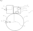
- FIG. 1 represents a schematic view of a vehicle 1 configured to move in a movement zone.
- Vehicle 1 can be interpreted as any land vehicle capable of moving by means of wheels.
- the vehicle 1 can be a robot capable of moving autonomously.
- the vehicle 1 comprises a chassis 10 and a wheel motor assembly 12.
- the chassis 10 is connected to the wheel motor assembly 12 which comprises a drive wheel 120 and an electric motor 122.
- the electric motor 122 is controlled by a controller (not shown ) delivering to the motor an electrical signal adapted for a given speed setpoint.
- the wheel motor assembly 12 is an assembly which includes the electric motor 122 incorporated directly in the driving wheel 120, which is capable of propelling the vehicle 1.
- the main advantages of such a wheel motor assembly 12 are its reduced size and the fact that it does not require transmission between the electric motor 122 and the drive wheel 120.
- the drive wheel 120 is then driven in rotation directly by the electric motor 120 along an axis of rotation A1.
- the electric motor 122 is at the level of a shaft driven by the drive wheel 120.
- the act of dissociating the electric motor 122 from the drive wheel 120 has the advantage of allowing the electric motor 122 to drive several drive wheels via the drive shaft.
- the vehicle 1 also includes an overspeed detection device 2 of the drive wheel 120.
- the overspeed detection device 2 is configured to detect when the vehicle 1 is in an overspeed situation in its travel zone.
- the overspeed detection device 2 comprises a first overspeed sensor 20 placed at the level of the driving wheel 120.
- the first overspeed sensor 20 comprises a fixed element 20' positioned in the driving wheel 120, or near its axis of rotation A1, and one or more movable elements 20" positioned along a radial end of the movable wheel 120 relative to the axis of rotation A1.
- the fixed element 20' is arranged so as to be immobile in the driving wheel 120 and makes it possible to have a reference measurement for the rotation of the driving wheel 120.
- the movable element 20" is fixed randomly against the driving wheel 120.
- the overspeed sensor 20 detects this complete rotation by tilting d 'an incomplete state to a complete state
- the incomplete state of the overspeed sensor 20 therefore reflects an incomplete rotation of the drive wheel 120 and the movable element 20" while the complete state reflects a complete rotation, it is that is to say at 360°, of the drive wheel 120 and the movable element 20".
- the first overspeed sensor 20 switches again to the incomplete state until detecting a new complete rotation of the drive wheel 120.
- the first overspeed sensor 20 is then configured to measure a rotation speed of the drive wheel 120.
- the fixed element 20' of the first overspeed sensor 20 is positioned by relative to a defined frame of reference, for example near the end of the driving wheel 120 at a known angle. Therefore, it is possible for the overspeed sensor 20 to measure an angle of rotation of the drive wheel 120 during the rotation of the drive wheel 120 or even an angle of rotation of the movable element 20" relative to the element fixed 20' of the overspeed sensor 20.
- the frame of reference can be any point such as the point of contact between the driving wheel 120 and the interface on which the driving wheel 120 moves.
- the fixed element 20' and the movable element(s) 20" are preferably arranged so as to be at a short distance from each other in order to improve the detection of the first overspeed sensor. And, according to an ideal variant , the movable element(s) 20" are arranged as close as possible to the fixed element 20' without the fixed element 20' being in contact with the movable element(s) 20". indicative, the fixed element 20' is distant from the movable element(s) by a distance of less than 15 millimeters.
- the overspeed sensor 20 acts as an angular position sensor of the movable element 20" in relation to the fixed element 20' and in relation to the defined reference frame and as a rotation speed sensor via the measurement of the switching frequency from the incomplete state to the complete state of the overspeed sensor 20.
- the overspeed detection device 2 also includes a speed reference device 22 configured to establish a maximum rotation speed of the drive wheel 120.
- the speed reference device 22 ensures the function of securing the rotation of the drive wheel 120 and makes it possible to define the material and functional limits of the drive wheel 120 when the drive wheel 120 is in motion.
- the speed reference device 22 comprises a lidar sensor 220 configured to determine an environment close to the driving wheel 120.
- the lidar sensor 220 is fixed to the chassis 10 so as to be able to emit a light wave in a predefined direction continuously.
- the lidar sensor 220 emits a light wave in a direction of movement of the vehicle 1 so as to allow the lidar sensor 220 to detect quickly enough any obstacle present in front of the vehicle 1 and which could cause an accident.
- the speed reference device 22 can include several lidar sensors 220 oriented in different directions so as to be able to carry out a more complete mapping of the environment close to the vehicle 1.
- the environment close to the vehicle 1 is defined as the area near the vehicle 1 subjected to the light waves of the lidar sensor 220.
- the near environment is therefore a zone close and accessible to the vehicle 1 included in the movement zone of the vehicle and mapped by the 220 lidar sensor.
- the nearby environment can also be interpreted as the critical zone of the vehicle 1 in which it is possible that the vehicle 1 encounters an obstacle during its movement and identifiable by the lidar sensor 220.
- the notion of proximity can also be interpreted as a distance between an object identified by the lidar sensor 220 and the vehicle 1 weak enough to risk a collision.
- the nearby environment depends in particular on the rotation speed of the drive wheel 120.
- the speed reference device 22 makes it possible to establish a maximum rotation speed of the drive wheel 120 in order to limit the speed of movement of the vehicle when the environment close to the vehicle 1 identified by the lidar sensor 220 presents obstacles likely to lead to collisions.
- the maximum rotation speed of the drive wheel 120 is then a speed calculated by the speed reference device 22 as a function of the nearby environment, a predefined functional speed threshold and a direction of rotation of the wheel. More precisely, the functional speed threshold defines the maximum speed at which vehicle 1 can functionally move and perform the function for which vehicle 1 was defined.
- the speed reference device 22 establishes a low maximum rotational speed of the drive wheel 120.
- the reference device can also establish a lower maximum rotational speed of the drive wheel 120 when the vehicle 1 is loaded and the functional speed threshold is lower.
- the maximum rotation speed is an indicative speed. Indeed, the maximum rotation speed must be interpreted as the speed at which the driving wheel 120 must move in order to respect the information linked to its environment. close and how it works.
- the maximum rotational speed of the drive wheel is therefore a speed reference which fluctuates in real time depending on the parameters mentioned above.
- the overspeed detection device 2 also includes a speed comparator 24 configured to compare the rotation speed of the drive wheel 120 and the maximum rotation speed of the drive wheel 120 established by the speed reference device 22.
- the overspeed comparator speed 24 is also configured to stop the rotation of the drive wheel 120 if the rotation speed of the drive wheel 120 is greater than the maximum rotation speed of the drive wheel 120 established by the speed reference device 22.
- the speed comparator 24 then acts directly on the electric motor 122 to brake the electric motor 122 and the drive wheel 120.
- the speed comparator 24 can also act on the electric motor 122 to stop the drive wheel 120. The speed comparator 24 thus makes it possible to act as a safety device against a potential situation of overspeed of the drive wheel 120 and the vehicle 1 by stopping the rotation of the drive wheel 120.
- Such an embodiment advantageously allows the speed comparator 24 to provide a safety function in the event of overspeed, for example due to a failure of the controller.
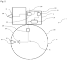
- the first overspeed sensor 20 may comprise a signal converter 200, as shown in figure 2 , configured to convert a toggle frequency of the first overspeed sensor 20 into a binary signal or an analog signal.
- the signal converter 200 is configured to convert the switching frequency of the first overspeed sensor 20 into an analog voltage.
- the converter of signal 200 can generate an electrical signal between 0 volts and 5 volts in order to measure the rotation speed of the drive wheel 120.
- the use of the overspeed detection device 2, and more particularly of the first overspeed sensor 20, the speed comparator 24 and the signal converter 200 thus has the advantage of dissociating the management of the speed of the vehicle and the wheel motor 120 and general management of the autonomous vehicle by the controller.
- the overspeed detection device 2 thus comprises a set of simple components or logic gates such as the signal converter 200 operating separately from the controller which includes digital and complex components.
- the overspeed detection device 2 is therefore a simple and reliable system to allow the management of the speed of the autonomous vehicle in relation to the digital and fallible controller.
- the detection of overspeed is therefore independent of the operation of the autonomous vehicle and particularly of the digital controller.
- the overspeed sensor 20 can also be configured to measure an angle of rotation between the movable element 20" and the fixed element 20'. Indeed, when the speed of rotation of the drive wheel 120 is low, the The switching frequency of the overspeed sensor 20 is also low and it then becomes difficult to measure this rotation speed. Knowing this angle of rotation then makes it possible to measure the rotation speed of the drive wheel 120 without detecting a complete rotation of the drive wheel. driving wheel 120.
- the signal converter 200 can also make it possible to measure this angle of rotation via a signal slot for example or any other periodic or even periodic signal of frequency proportional to the rotation speed of the electric motor 120.
- the first overspeed sensor 20 makes it possible to measure a complete rotation or an angle of rotation of the drive wheel 120 and the rotation speed of the drive wheel 120 via the rocking frequency of the first overspeed sensor 20 between the incomplete and complete state.
- the lidar sensor 220 is thus configured to identify or digitally represent the environment close to the vehicle 1 by means of a first mapping 222.
- the lidar sensor 220 makes it possible, through this first mapping 222, to scan the nearby environment and to know where are the objects in its field of vision and at what distance from vehicle 1.
- an attention zone of the vehicle 1 in the first mapping 222 can also be envisaged to program, in the lidar sensor 220 via a second programming input 224, an attention zone of the vehicle 1 in the first mapping 222. Programming this attention zone allows a user to define, in the movement zone of the vehicle 1, zones in which the vehicle 1 must not move or must move at restricted speeds. These attention zones can thus be interpreted as critical zones where a collision is strongly anticipated.
- lidar sensor 220 can also be considered to replace the lidar sensor 220 with another optical or proximity sensor such as a sonar, a ToF sensor or even a camera.
- another optical or proximity sensor such as a sonar, a ToF sensor or even a camera.
- the speed reference device 22 establishes the maximum rotational speed of the drive wheel 120.
- the speed reference device can also take into account consideration of other input parameters such as vehicle hardware limitations 1.
- the overspeed detection device 2 can comprise a second overspeed sensor 26, as shown in Figure 3 , fixed to the drive wheel 120 and arranged at a predefined angle relative to the first overspeed sensor 20.
- the second overspeed sensor 26 comprises a fixed element 26' of the second overspeed sensor positioned near the axis of rotation A1 of the drive wheel 120 and a movable element 26" of the second overspeed sensor 26 positioned along a radial end of the movable wheel 120 relative to the axis of rotation A1, the movable element 26" being arranged at a predefined angle relative to the movable element 20" of the first overspeed sensor 20.
- the second overspeed sensor 26 is configured to measure a rotational speed of the wheel. In other words, the second overspeed sensor. 26 makes it possible to measure a complete rotation or an angle of rotation of the drive wheel 120 and the rotation speed of the drive wheel 120 via a switching frequency of the second overspeed sensor 26 between the incomplete and complete state .
- a second overspeed sensor 26 thus has the advantage of obtaining data linked to the rotation of the drive wheel 120 providing redundancy with respect to the data measured by the first overspeed sensor 20.
- the second overspeed sensor 26 also has the advantage of making it possible to measure a rotational speed of the wheel without requiring complete rotation of the drive wheel 120.
- vehicle 1 generally moves at relatively low speeds, less than three kilometers per hour. Therefore, the time necessary to obtain a first quantifiable data of the rotation speed of the drive wheel 120 can generally require a relatively long delay.
- the environment close to the vehicle 1 can easily change and an obstacle in the close environment can appear in front of the vehicle, transforming a situation of nominal operation of the vehicle 1 into one. potential dangerous collision situation.
- the use of a second overspeed sensor 26 at a predefined angle relative to the first overspeed sensor 20 thus makes it possible to limit the duration necessary for the measurement of the rotation of the drive wheel 120 and its rotation speed since this measurement is given when the angle between the first overspeed sensor 20 and the second overspeed sensor 26 is completed.
- the overspeed detection device 2 can include a third overspeed sensor 28 also fixed to the drive wheel 120 and arranged at a predefined angle relative to the drive wheel 120. to the first overspeed sensor 20 and with respect to the second overspeed sensor 26.
- the third overspeed sensor 28 comprises a fixed element 28' of the third overspeed sensor 28 positioned near the axis of rotation A1 of the driving wheel 120 and a movable element 28" of the third overspeed sensor 28 positioned along a radial end of the movable wheel 120 relative to the axis of rotation A1, the movable element 28" of the third overspeed sensor 28 being arranged at a predefined angle with respect to the movable element 20" of the first overspeed sensor 20 and with respect to the movable element 26" of the second overspeed sensor 26.
- the third overspeed sensor is also configured to measure a rotation speed of the drive wheel 120. In other words, the third overspeed sensor 28 makes it possible to measure a complete rotation or an angle of rotation of the drive wheel 120 and the rotation speed of the driving wheel 120 via a switching frequency of the third overspeed sensor 28 between the incomplete and complete state.
- overspeed sensors 20, 26 and 28 thus has the advantage of allowing uniform angular distribution in the driving wheel 120 without cluttering the wheel motor assembly 12.
- an overspeed sensor among the first sensor overspeed 20, the second overspeed sensor 26 or the third overspeed sensor 28 does not operate correctly, the overspeed detection device 2 is not impacted in its measurement of the rotation speed of the drive wheel 120.
- the multiplication of overspeed sensors also makes it possible to meet a redundancy requirement in terms of safety.
- the first overspeed sensor 20, the second overspeed sensor 26 and the third overspeed sensor 28 share the same and single fixed element, namely for example the fixed element 20' of the first overspeed sensor 20 and each comprise a predefined number of mobile elements, so that the overspeed detection device 2 comprises a predefined sum of mobile elements distributed uniformly on the drive wheel 120.
- each overspeed sensor can comprise ten mobile elements so that the overspeed detection device 2 comprises thirty mobile elements distributed uniformly on the drive wheel 120
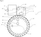
- a single overspeed sensor for example the first overspeed sensor 20, can be the only overspeed sensor included in the overspeed detection device 2 and the first overspeed sensor can comprise thirty mobile elements distributed over the wheel motor 120 as shown in figure 5 .
- the signal converter 200 which must process slow signals, is thus capable of transcribing according to an analog signal a predefined number, namely according to our example thirty, of flip-flops between the complete state and the incomplete state during a rotation complete with the drive wheel.
- the first overspeed sensor 20 changes state between the incomplete state and the complete state every twelve degrees.
- Multiplying the number of mobile elements 20" and therefore the number of switches of the first overspeed sensor 20 between the incomplete state and the complete state thus has the advantage of improving the reaction of the overspeed detection device, as said previously, the drive wheel rotating at a relatively low rotation speed and the fact that no reduction between the electric motor 122 and the drive wheel 120 is installed, the switches between the complete state and the incomplete state.
- of the first overspeed sensor are made, thanks to the use of thirty moving elements, at a frequency of 7.8Hz at one kilometer per hour for example, and therefore over a period of 128 milliseconds.
- the detection device. overspeed to have a rapid reaction time, that is to say less than 300 milliseconds, which is advantageously the case when the first overspeed sensor 20 comprises thirty mobile elements 20".
- a filter 240 in the first overspeed sensor 20 at the output of the signal converter 200 is added.
- the filter 240 is arranged between the signal converter 200 and the speed comparator 24.
- the filter at the output of the signal converter 200 must be dimensioned to be able to produce a sufficiently smooth voltage for the speed comparator 24 to be able to perform a comparison while impacting as little as possible the time linked to providing the speed measurement of the drive wheel 120 and to the comparison between the measurement of the rotation speed of the drive wheel 120 and the maximum rotation speed of the drive wheel 120 authorized.
- the filter 240 is a third-order filter.
- the filter 240 can be a filter composed of an RC low pass filter, composed of a resistor and a capacitor, of 1st order cascaded with an active Sallen Key filter.
- the Sallen Key filter can be replaced by two 1st order RC low pass filters or by a 2nd order LC passive filter, composed of a coil and a capacitor, for example.
- the overspeed detection device 2 may also include a generalized malfunction detector 29 of the first overspeed sensor 20, the second overspeed sensor 26 and the third overspeed sensor 28, as shown in Figure 4 , intended to detect a simultaneous operating fault of the first overspeed sensor 20 and the second overspeed sensor 26 or the second overspeed sensor 26 and the third overspeed sensor 28 or the first overspeed sensor 20 and the third overspeed sensor 28 or else the first overspeed sensor 20, the second overspeed sensor 26 and the third overspeed sensor 28.
- a generalized malfunction detector 29 of the first overspeed sensor 20, the second overspeed sensor 26 and the third overspeed sensor 28, as shown in Figure 4 intended to detect a simultaneous operating fault of the first overspeed sensor 20 and the second overspeed sensor 26 or the second overspeed sensor 26 and the third overspeed sensor 28 or the first overspeed sensor 20 and the third overspeed sensor 28 or else the first overspeed sensor 20, the second overspeed sensor 26 and the third overspeed sensor 28.
- the generalized operating fault detector 29 detects that two overspeed sensors are not operating correctly then the generalized operating fault detector informs the user of degraded operation of the overspeed detection device 2. And when the detector generalized malfunction detector 29 detects that the three overspeed sensors 20, 26 and 28 are not functioning correctly then the generalized malfunction detector informs the user of a malfunction of the overspeed detection device 2.
- first overspeed sensor 20, the second overspeed sensor 26 and/or the third overspeed sensor 28 may be hall effect sensors. These sensors have a simple architecture and are very easily incorporated into the wheel 12 motor assembly.
- each overspeed sensor delivering a binary signal
- the generalized malfunction detector 29 to generate a simultaneous detection of the state of each overspeed sensor among the first overspeed sensor 20, the second overspeed sensor 26 and the third overspeed sensor 28.
- the fault detector generalized operation informs the user of a malfunction of the overspeed detection device 2.
- the generalized operating fault detector 29 thus makes it possible to prevent a common cause failure which leads to the loss of the entire monitoring function of the overspeed of the vehicle 1.
- the signals from each of the first, second and third hall effect overspeed sensors are phase shifted to know approximately the position angle of the electric motor 122.
- Each hall effect overspeed sensor among the first, the second and the third overspeed sensor can give a binary signal, which includes eight possible combinations. However, only six signal combinations are possible for a desired arrangement of the first, second and third hall effect overspeed sensors. Therefore, the generalized operating fault detector 29 makes it possible to determine if one of the two “impossible” combinations is obtained and reflects the fault of an overspeed sensor among the first overspeed sensor 20, the second overspeed sensor 26 or the third overspeed sensor 28.
- first overspeed sensor 20, the second overspeed sensor 26 and/or the third overspeed sensor 28 may be rotary sensors or optical sensors.
- the invention works for an electric motor 10 commonly called in the Anglo-Saxon literature: "in wheel”, that is to say an motor directly connected to a driving wheel itself driven by the electric motor 122.
- in wheel that is to say an motor directly connected to a driving wheel itself driven by the electric motor 122.
- a vehicle 1 may comprise this type of wheel motor assembly 12 and overspeed detection device 2 may be an autonomous vehicle such as for example a robot or an autonomous delivery robot or even a remotely controlled vehicle such as a controlled delivery robot .
- the invention thus has the advantage of making it possible to detect overspeed on the part of the autonomous mobile vehicle during its movement in its movement zone as a function of its immediate environment by the coupled use of a sensor positioned directly in the drive wheel. and a lidar-type sensory sensor making it possible to stop the vehicle 1 when the situation seems critical.
Landscapes
- Engineering & Computer Science (AREA)
- Physics & Mathematics (AREA)
- General Physics & Mathematics (AREA)
- Mechanical Engineering (AREA)
- Transportation (AREA)
- Electromagnetism (AREA)
- Radar, Positioning & Navigation (AREA)
- Computer Networks & Wireless Communication (AREA)
- Power Engineering (AREA)
- Remote Sensing (AREA)
- Combustion & Propulsion (AREA)
- Chemical & Material Sciences (AREA)
- Automation & Control Theory (AREA)
- Mathematical Physics (AREA)
- Robotics (AREA)
- Electric Propulsion And Braking For Vehicles (AREA)
- Control Of Electric Motors In General (AREA)
Applications Claiming Priority (1)
| Application Number | Priority Date | Filing Date | Title |
|---|---|---|---|
| FR2211515A FR3141634B1 (fr) | 2022-11-04 | 2022-11-04 | Dispositif de détection de survitesse |
Publications (1)
| Publication Number | Publication Date |
|---|---|
| EP4364904A1 true EP4364904A1 (de) | 2024-05-08 |
Family
ID=85017888
Family Applications (1)
| Application Number | Title | Priority Date | Filing Date |
|---|---|---|---|
| EP23206669.6A Withdrawn EP4364904A1 (de) | 2022-11-04 | 2023-10-30 | Vorrichtung zur erkennung von überdrehzahlen |
Country Status (5)
| Country | Link |
|---|---|
| US (1) | US20240149702A1 (de) |
| EP (1) | EP4364904A1 (de) |
| JP (1) | JP2024068176A (de) |
| KR (1) | KR20240068045A (de) |
| FR (1) | FR3141634B1 (de) |
Families Citing this family (1)
| Publication number | Priority date | Publication date | Assignee | Title |
|---|---|---|---|---|
| EP4573863A1 (de) * | 2023-12-19 | 2025-06-25 | CNH Industrial Belgium N.V. | Verbesserungen zur diagnose von zapfwellengeschwindigkeitssensoren |
Citations (3)
| Publication number | Priority date | Publication date | Assignee | Title |
|---|---|---|---|---|
| KR100585680B1 (ko) * | 2004-12-10 | 2006-06-07 | 엘지전자 주식회사 | 이동 로봇의 구동바퀴 속도지령치 생성방법 |
| US20150183432A1 (en) * | 2012-06-21 | 2015-07-02 | Remote Control Technologies Pty Ltd | Speed control system |
| WO2022134863A1 (zh) * | 2020-12-25 | 2022-06-30 | 优必选北美研发中心公司 | 防撞方法、移动机器及存储介质 |
Family Cites Families (7)
| Publication number | Priority date | Publication date | Assignee | Title |
|---|---|---|---|---|
| GB0916369D0 (en) * | 2009-09-18 | 2009-10-28 | Schrader Electronics Ltd | Tracking filter apparatus for wheel monitoring systems |
| JP2014214606A (ja) * | 2013-04-22 | 2014-11-17 | 新電元工業株式会社 | 制御装置、および、制御装置の制御方法 |
| DE102015216494A1 (de) * | 2015-08-28 | 2017-03-02 | Robert Bosch Gmbh | Verfahren und Vorrichtung zur Erkennung wenigstens einer Sensorfunktion wenigstens eines ersten Sensor wenigstens eines ersten Fahrzeugs |
| JP6651374B2 (ja) * | 2016-02-12 | 2020-02-19 | Ntn株式会社 | 車輪独立駆動式車両の駆動制御装置 |
| JP2020102931A (ja) * | 2018-12-21 | 2020-07-02 | トヨタ自動車株式会社 | 車両の駆動制御装置 |
| FR3099735B1 (fr) * | 2019-08-06 | 2024-09-06 | Electricite De France | Système d’acquisition et de contrôle pour véhicule à moteur électrique |
| JP7190665B2 (ja) * | 2019-12-24 | 2022-12-16 | パナソニックIpマネジメント株式会社 | 車両制御装置、及び、車両 |
-
2022
- 2022-11-04 FR FR2211515A patent/FR3141634B1/fr active Active
-
2023
- 2023-10-30 US US18/385,301 patent/US20240149702A1/en not_active Abandoned
- 2023-10-30 EP EP23206669.6A patent/EP4364904A1/de not_active Withdrawn
- 2023-11-02 JP JP2023188224A patent/JP2024068176A/ja active Pending
- 2023-11-03 KR KR1020230151058A patent/KR20240068045A/ko active Pending
Patent Citations (3)
| Publication number | Priority date | Publication date | Assignee | Title |
|---|---|---|---|---|
| KR100585680B1 (ko) * | 2004-12-10 | 2006-06-07 | 엘지전자 주식회사 | 이동 로봇의 구동바퀴 속도지령치 생성방법 |
| US20150183432A1 (en) * | 2012-06-21 | 2015-07-02 | Remote Control Technologies Pty Ltd | Speed control system |
| WO2022134863A1 (zh) * | 2020-12-25 | 2022-06-30 | 优必选北美研发中心公司 | 防撞方法、移动机器及存储介质 |
Also Published As
| Publication number | Publication date |
|---|---|
| JP2024068176A (ja) | 2024-05-17 |
| FR3141634A1 (fr) | 2024-05-10 |
| KR20240068045A (ko) | 2024-05-17 |
| FR3141634B1 (fr) | 2026-01-16 |
| US20240149702A1 (en) | 2024-05-09 |
Similar Documents
| Publication | Publication Date | Title |
|---|---|---|
| EP0484194B1 (de) | Drehwinkelsensor | |
| EP2448804B1 (de) | System zur elektrischen sperre einer lenksäule und lenksäule mit einem solchen sperrsystem | |
| FR2593765A1 (fr) | Systeme de direction electrique pour vehicules | |
| CA2742643C (fr) | Dispositif de deplacement autonome pour aeronef | |
| WO2015033034A1 (fr) | Interface de commande à retour haptique | |
| EP4364904A1 (de) | Vorrichtung zur erkennung von überdrehzahlen | |
| EP0194930B1 (de) | Elektrooptische Torsionsmessvorrichtung für einen Antriebsmechanismus | |
| FR2484887A1 (fr) | Appareil de positionnement repere permettant de faire tourner a ses reperes une table rotative | |
| FR2854110A1 (fr) | Dispositif d'entrainement en rotation | |
| WO2022200040A1 (fr) | Système de gestion d'anticollision d'une grue mobile sur un chantier | |
| FR2495797A1 (fr) | Systeme de pilotage automatique d'un vehicule terrestre autonome | |
| EP1045588B1 (de) | Vorrichtung zur Übertragung von digitalen Videobildern | |
| FR2703450A1 (fr) | Codeur numérique incrémental absolu, installation et machine comportant ce codeur. | |
| WO2002086515A1 (fr) | Dispositif de lecture de vitesse de rotation pour pulverisateur de peinture a bol tournant | |
| FR3123776A1 (fr) | Calibrage embarqué d'une matrice de pixels d'un capteur infrarouge | |
| EP2683579B1 (de) | Verfahren und vorrichtung zur steuerung eines fahrzeug-wischermotors | |
| FR2480191A1 (fr) | Installation pour la commande et la surveillance d'organes de reglage pour machines a imprimer | |
| EP2602601A1 (de) | Überwachungssystem einer kinematischen Kette | |
| FR2802495A1 (fr) | Dispositif de direction, en particulier pour chariot elevateur | |
| EP0959362A1 (de) | Vorrichtung zur Messung einer mit der Rotation eines Organs zusammenhängenden physikalischen Grösse | |
| JP7534546B2 (ja) | レーザースキャナーの操作性の検証 | |
| FR2782689A1 (fr) | Bogie de vehicule ferroviaire, procede d'usinage de ce bogie et outil pour la mise en oeuvre de ce procede | |
| WO2017006050A1 (fr) | Dispositif de detection d'une position neutre d'une commande de vitesses d'une boite de vitesses d'un vehicule automobile | |
| EP4392610A1 (de) | Zugangskontrollvorrichtung mit gyroskopischem sensor | |
| WO2025022077A1 (fr) | Système de détection de secteurs angulaires, notamment pour plateforme gyrostabilisée sur un véhicule de type aéronef |
Legal Events
| Date | Code | Title | Description |
|---|---|---|---|
| PUAI | Public reference made under article 153(3) epc to a published international application that has entered the european phase |
Free format text: ORIGINAL CODE: 0009012 |
|
| STAA | Information on the status of an ep patent application or granted ep patent |
Free format text: STATUS: THE APPLICATION HAS BEEN PUBLISHED |
|
| AK | Designated contracting states |
Kind code of ref document: A1 Designated state(s): AL AT BE BG CH CY CZ DE DK EE ES FI FR GB GR HR HU IE IS IT LI LT LU LV MC ME MK MT NL NO PL PT RO RS SE SI SK SM TR |
|
| STAA | Information on the status of an ep patent application or granted ep patent |
Free format text: STATUS: REQUEST FOR EXAMINATION WAS MADE |
|
| 17P | Request for examination filed |
Effective date: 20241107 |
|
| GRAP | Despatch of communication of intention to grant a patent |
Free format text: ORIGINAL CODE: EPIDOSNIGR1 |
|
| RBV | Designated contracting states (corrected) |
Designated state(s): AL AT BE BG CH CY CZ DE DK EE ES FI FR GB GR HR HU IE IS IT LI LT LU LV MC ME MK MT NL NO PL PT RO RS SE SI SK SM TR |
|
| STAA | Information on the status of an ep patent application or granted ep patent |
Free format text: STATUS: GRANT OF PATENT IS INTENDED |
|
| RIC1 | Information provided on ipc code assigned before grant |
Ipc: G05D 1/00 20240101ALI20241127BHEP Ipc: B25J 5/00 20060101ALI20241127BHEP Ipc: B25J 9/16 20060101AFI20241127BHEP |
|
| INTG | Intention to grant announced |
Effective date: 20241212 |
|
| STAA | Information on the status of an ep patent application or granted ep patent |
Free format text: STATUS: THE APPLICATION IS DEEMED TO BE WITHDRAWN |
|
| 18D | Application deemed to be withdrawn |
Effective date: 20250415 |