EP4364989A1 - Antriebssystem für elektrofahrzeug und elektrofahrzeug - Google Patents
Antriebssystem für elektrofahrzeug und elektrofahrzeug Download PDFInfo
- Publication number
- EP4364989A1 EP4364989A1 EP21950410.7A EP21950410A EP4364989A1 EP 4364989 A1 EP4364989 A1 EP 4364989A1 EP 21950410 A EP21950410 A EP 21950410A EP 4364989 A1 EP4364989 A1 EP 4364989A1
- Authority
- EP
- European Patent Office
- Prior art keywords
- transmission
- generator
- engine
- electric vehicle
- clutch
- Prior art date
- Legal status (The legal status is an assumption and is not a legal conclusion. Google has not performed a legal analysis and makes no representation as to the accuracy of the status listed.)
- Granted
Links
Images







Classifications
-
- B—PERFORMING OPERATIONS; TRANSPORTING
- B60—VEHICLES IN GENERAL
- B60K—ARRANGEMENT OR MOUNTING OF PROPULSION UNITS OR OF TRANSMISSIONS IN VEHICLES; ARRANGEMENT OR MOUNTING OF PLURAL DIVERSE PRIME-MOVERS IN VEHICLES; AUXILIARY DRIVES FOR VEHICLES; INSTRUMENTATION OR DASHBOARDS FOR VEHICLES; ARRANGEMENTS IN CONNECTION WITH COOLING, AIR INTAKE, GAS EXHAUST OR FUEL SUPPLY OF PROPULSION UNITS IN VEHICLES
- B60K6/00—Arrangement or mounting of plural diverse prime-movers for mutual or common propulsion, e.g. hybrid propulsion systems comprising electric motors and internal combustion engines
- B60K6/20—Arrangement or mounting of plural diverse prime-movers for mutual or common propulsion, e.g. hybrid propulsion systems comprising electric motors and internal combustion engines the prime-movers consisting of electric motors and internal combustion engines, e.g. HEVs
- B60K6/22—Arrangement or mounting of plural diverse prime-movers for mutual or common propulsion, e.g. hybrid propulsion systems comprising electric motors and internal combustion engines the prime-movers consisting of electric motors and internal combustion engines, e.g. HEVs characterised by apparatus, components or means specially adapted for HEVs
- B60K6/36—Arrangement or mounting of plural diverse prime-movers for mutual or common propulsion, e.g. hybrid propulsion systems comprising electric motors and internal combustion engines the prime-movers consisting of electric motors and internal combustion engines, e.g. HEVs characterised by apparatus, components or means specially adapted for HEVs characterised by the transmission gearings
-
- B—PERFORMING OPERATIONS; TRANSPORTING
- B60—VEHICLES IN GENERAL
- B60K—ARRANGEMENT OR MOUNTING OF PROPULSION UNITS OR OF TRANSMISSIONS IN VEHICLES; ARRANGEMENT OR MOUNTING OF PLURAL DIVERSE PRIME-MOVERS IN VEHICLES; AUXILIARY DRIVES FOR VEHICLES; INSTRUMENTATION OR DASHBOARDS FOR VEHICLES; ARRANGEMENTS IN CONNECTION WITH COOLING, AIR INTAKE, GAS EXHAUST OR FUEL SUPPLY OF PROPULSION UNITS IN VEHICLES
- B60K6/00—Arrangement or mounting of plural diverse prime-movers for mutual or common propulsion, e.g. hybrid propulsion systems comprising electric motors and internal combustion engines
- B60K6/20—Arrangement or mounting of plural diverse prime-movers for mutual or common propulsion, e.g. hybrid propulsion systems comprising electric motors and internal combustion engines the prime-movers consisting of electric motors and internal combustion engines, e.g. HEVs
- B60K6/22—Arrangement or mounting of plural diverse prime-movers for mutual or common propulsion, e.g. hybrid propulsion systems comprising electric motors and internal combustion engines the prime-movers consisting of electric motors and internal combustion engines, e.g. HEVs characterised by apparatus, components or means specially adapted for HEVs
- B60K6/26—Arrangement or mounting of plural diverse prime-movers for mutual or common propulsion, e.g. hybrid propulsion systems comprising electric motors and internal combustion engines the prime-movers consisting of electric motors and internal combustion engines, e.g. HEVs characterised by apparatus, components or means specially adapted for HEVs characterised by the motors or the generators
-
- B—PERFORMING OPERATIONS; TRANSPORTING
- B60—VEHICLES IN GENERAL
- B60K—ARRANGEMENT OR MOUNTING OF PROPULSION UNITS OR OF TRANSMISSIONS IN VEHICLES; ARRANGEMENT OR MOUNTING OF PLURAL DIVERSE PRIME-MOVERS IN VEHICLES; AUXILIARY DRIVES FOR VEHICLES; INSTRUMENTATION OR DASHBOARDS FOR VEHICLES; ARRANGEMENTS IN CONNECTION WITH COOLING, AIR INTAKE, GAS EXHAUST OR FUEL SUPPLY OF PROPULSION UNITS IN VEHICLES
- B60K6/00—Arrangement or mounting of plural diverse prime-movers for mutual or common propulsion, e.g. hybrid propulsion systems comprising electric motors and internal combustion engines
- B60K6/20—Arrangement or mounting of plural diverse prime-movers for mutual or common propulsion, e.g. hybrid propulsion systems comprising electric motors and internal combustion engines the prime-movers consisting of electric motors and internal combustion engines, e.g. HEVs
- B60K6/22—Arrangement or mounting of plural diverse prime-movers for mutual or common propulsion, e.g. hybrid propulsion systems comprising electric motors and internal combustion engines the prime-movers consisting of electric motors and internal combustion engines, e.g. HEVs characterised by apparatus, components or means specially adapted for HEVs
- B60K6/38—Arrangement or mounting of plural diverse prime-movers for mutual or common propulsion, e.g. hybrid propulsion systems comprising electric motors and internal combustion engines the prime-movers consisting of electric motors and internal combustion engines, e.g. HEVs characterised by apparatus, components or means specially adapted for HEVs characterised by the driveline clutches
-
- B—PERFORMING OPERATIONS; TRANSPORTING
- B60—VEHICLES IN GENERAL
- B60K—ARRANGEMENT OR MOUNTING OF PROPULSION UNITS OR OF TRANSMISSIONS IN VEHICLES; ARRANGEMENT OR MOUNTING OF PLURAL DIVERSE PRIME-MOVERS IN VEHICLES; AUXILIARY DRIVES FOR VEHICLES; INSTRUMENTATION OR DASHBOARDS FOR VEHICLES; ARRANGEMENTS IN CONNECTION WITH COOLING, AIR INTAKE, GAS EXHAUST OR FUEL SUPPLY OF PROPULSION UNITS IN VEHICLES
- B60K6/00—Arrangement or mounting of plural diverse prime-movers for mutual or common propulsion, e.g. hybrid propulsion systems comprising electric motors and internal combustion engines
- B60K6/20—Arrangement or mounting of plural diverse prime-movers for mutual or common propulsion, e.g. hybrid propulsion systems comprising electric motors and internal combustion engines the prime-movers consisting of electric motors and internal combustion engines, e.g. HEVs
- B60K6/22—Arrangement or mounting of plural diverse prime-movers for mutual or common propulsion, e.g. hybrid propulsion systems comprising electric motors and internal combustion engines the prime-movers consisting of electric motors and internal combustion engines, e.g. HEVs characterised by apparatus, components or means specially adapted for HEVs
- B60K6/38—Arrangement or mounting of plural diverse prime-movers for mutual or common propulsion, e.g. hybrid propulsion systems comprising electric motors and internal combustion engines the prime-movers consisting of electric motors and internal combustion engines, e.g. HEVs characterised by apparatus, components or means specially adapted for HEVs characterised by the driveline clutches
- B60K6/387—Actuated clutches, i.e. clutches engaged or disengaged by electric, hydraulic or mechanical actuating means
-
- B—PERFORMING OPERATIONS; TRANSPORTING
- B60—VEHICLES IN GENERAL
- B60K—ARRANGEMENT OR MOUNTING OF PROPULSION UNITS OR OF TRANSMISSIONS IN VEHICLES; ARRANGEMENT OR MOUNTING OF PLURAL DIVERSE PRIME-MOVERS IN VEHICLES; AUXILIARY DRIVES FOR VEHICLES; INSTRUMENTATION OR DASHBOARDS FOR VEHICLES; ARRANGEMENTS IN CONNECTION WITH COOLING, AIR INTAKE, GAS EXHAUST OR FUEL SUPPLY OF PROPULSION UNITS IN VEHICLES
- B60K6/00—Arrangement or mounting of plural diverse prime-movers for mutual or common propulsion, e.g. hybrid propulsion systems comprising electric motors and internal combustion engines
- B60K6/20—Arrangement or mounting of plural diverse prime-movers for mutual or common propulsion, e.g. hybrid propulsion systems comprising electric motors and internal combustion engines the prime-movers consisting of electric motors and internal combustion engines, e.g. HEVs
- B60K6/42—Arrangement or mounting of plural diverse prime-movers for mutual or common propulsion, e.g. hybrid propulsion systems comprising electric motors and internal combustion engines the prime-movers consisting of electric motors and internal combustion engines, e.g. HEVs characterised by the architecture of the hybrid electric vehicle
- B60K6/44—Series-parallel type
- B60K6/442—Series-parallel switching type
-
- B—PERFORMING OPERATIONS; TRANSPORTING
- B60—VEHICLES IN GENERAL
- B60K—ARRANGEMENT OR MOUNTING OF PROPULSION UNITS OR OF TRANSMISSIONS IN VEHICLES; ARRANGEMENT OR MOUNTING OF PLURAL DIVERSE PRIME-MOVERS IN VEHICLES; AUXILIARY DRIVES FOR VEHICLES; INSTRUMENTATION OR DASHBOARDS FOR VEHICLES; ARRANGEMENTS IN CONNECTION WITH COOLING, AIR INTAKE, GAS EXHAUST OR FUEL SUPPLY OF PROPULSION UNITS IN VEHICLES
- B60K6/00—Arrangement or mounting of plural diverse prime-movers for mutual or common propulsion, e.g. hybrid propulsion systems comprising electric motors and internal combustion engines
- B60K6/20—Arrangement or mounting of plural diverse prime-movers for mutual or common propulsion, e.g. hybrid propulsion systems comprising electric motors and internal combustion engines the prime-movers consisting of electric motors and internal combustion engines, e.g. HEVs
- B60K6/42—Arrangement or mounting of plural diverse prime-movers for mutual or common propulsion, e.g. hybrid propulsion systems comprising electric motors and internal combustion engines the prime-movers consisting of electric motors and internal combustion engines, e.g. HEVs characterised by the architecture of the hybrid electric vehicle
- B60K6/48—Parallel type
-
- B—PERFORMING OPERATIONS; TRANSPORTING
- B60—VEHICLES IN GENERAL
- B60K—ARRANGEMENT OR MOUNTING OF PROPULSION UNITS OR OF TRANSMISSIONS IN VEHICLES; ARRANGEMENT OR MOUNTING OF PLURAL DIVERSE PRIME-MOVERS IN VEHICLES; AUXILIARY DRIVES FOR VEHICLES; INSTRUMENTATION OR DASHBOARDS FOR VEHICLES; ARRANGEMENTS IN CONNECTION WITH COOLING, AIR INTAKE, GAS EXHAUST OR FUEL SUPPLY OF PROPULSION UNITS IN VEHICLES
- B60K6/00—Arrangement or mounting of plural diverse prime-movers for mutual or common propulsion, e.g. hybrid propulsion systems comprising electric motors and internal combustion engines
- B60K6/20—Arrangement or mounting of plural diverse prime-movers for mutual or common propulsion, e.g. hybrid propulsion systems comprising electric motors and internal combustion engines the prime-movers consisting of electric motors and internal combustion engines, e.g. HEVs
- B60K6/50—Architecture of the driveline characterised by arrangement or kind of transmission units
- B60K6/52—Driving a plurality of drive axles, e.g. four-wheel drive
-
- B—PERFORMING OPERATIONS; TRANSPORTING
- B60—VEHICLES IN GENERAL
- B60K—ARRANGEMENT OR MOUNTING OF PROPULSION UNITS OR OF TRANSMISSIONS IN VEHICLES; ARRANGEMENT OR MOUNTING OF PLURAL DIVERSE PRIME-MOVERS IN VEHICLES; AUXILIARY DRIVES FOR VEHICLES; INSTRUMENTATION OR DASHBOARDS FOR VEHICLES; ARRANGEMENTS IN CONNECTION WITH COOLING, AIR INTAKE, GAS EXHAUST OR FUEL SUPPLY OF PROPULSION UNITS IN VEHICLES
- B60K6/00—Arrangement or mounting of plural diverse prime-movers for mutual or common propulsion, e.g. hybrid propulsion systems comprising electric motors and internal combustion engines
- B60K6/20—Arrangement or mounting of plural diverse prime-movers for mutual or common propulsion, e.g. hybrid propulsion systems comprising electric motors and internal combustion engines the prime-movers consisting of electric motors and internal combustion engines, e.g. HEVs
- B60K6/42—Arrangement or mounting of plural diverse prime-movers for mutual or common propulsion, e.g. hybrid propulsion systems comprising electric motors and internal combustion engines the prime-movers consisting of electric motors and internal combustion engines, e.g. HEVs characterised by the architecture of the hybrid electric vehicle
- B60K6/48—Parallel type
- B60K2006/4808—Electric machine connected or connectable to gearbox output shaft
-
- Y—GENERAL TAGGING OF NEW TECHNOLOGICAL DEVELOPMENTS; GENERAL TAGGING OF CROSS-SECTIONAL TECHNOLOGIES SPANNING OVER SEVERAL SECTIONS OF THE IPC; TECHNICAL SUBJECTS COVERED BY FORMER USPC CROSS-REFERENCE ART COLLECTIONS [XRACs] AND DIGESTS
- Y02—TECHNOLOGIES OR APPLICATIONS FOR MITIGATION OR ADAPTATION AGAINST CLIMATE CHANGE
- Y02T—CLIMATE CHANGE MITIGATION TECHNOLOGIES RELATED TO TRANSPORTATION
- Y02T10/00—Road transport of goods or passengers
- Y02T10/60—Other road transportation technologies with climate change mitigation effect
- Y02T10/62—Hybrid vehicles
-
- Y—GENERAL TAGGING OF NEW TECHNOLOGICAL DEVELOPMENTS; GENERAL TAGGING OF CROSS-SECTIONAL TECHNOLOGIES SPANNING OVER SEVERAL SECTIONS OF THE IPC; TECHNICAL SUBJECTS COVERED BY FORMER USPC CROSS-REFERENCE ART COLLECTIONS [XRACs] AND DIGESTS
- Y02—TECHNOLOGIES OR APPLICATIONS FOR MITIGATION OR ADAPTATION AGAINST CLIMATE CHANGE
- Y02T—CLIMATE CHANGE MITIGATION TECHNOLOGIES RELATED TO TRANSPORTATION
- Y02T10/00—Road transport of goods or passengers
- Y02T10/60—Other road transportation technologies with climate change mitigation effect
- Y02T10/7072—Electromobility specific charging systems or methods for batteries, ultracapacitors, supercapacitors or double-layer capacitors
Definitions
- This application relates to the field of vehicle technologies, and in particular, to an electric vehicle drive system and an electric vehicle.
- the electric vehicle mainly includes two types: a battery-driven electric vehicle and an electric vehicle driven by a combination of a battery and a fuel.
- a type of a hybrid electric vehicle an extended-range hybrid electric vehicle is widely used because a fuel engine can drive a generator to generate electricity and provide the electricity for a battery.
- a generator can only be configured to generate electricity. Therefore, to implement the hybrid solution, a separate generator needs to be configured on an original drive system.
- the newly added generator occupies a part of vehicle space, reduces available space for passengers, and increases costs of the electric vehicle.
- This application provides an electric vehicle drive system and an electric vehicle, to reduce driving costs of the electric vehicle, increase space of the electric vehicle, implement a four-wheel drive mode of the electric vehicle, and improve performance of the electric vehicle.
- an embodiment of this application provides an electric vehicle drive system.
- the electric vehicle drive system includes a first powertrain, a second powertrain, a first transmission system, a second transmission system, and a battery system.
- the first powertrain is connected to the first transmission system, and the first transmission system is in transmission connection to first-side wheels of an electric vehicle.
- the second powertrain is connected to the second transmission system, and the second transmission system is in transmission connection to second-side wheels of the electric vehicle.
- the first powertrain includes a generator and an engine, and the engine is configured to drive the generator to generate electric energy, or drive the first-side wheels by using the first transmission system.
- the generator is configured to drive the first-side wheels by using the first transmission system, or output the generated electric energy to the battery system.
- the second powertrain is in transmission connection to the second-side wheels by using the second transmission system.
- the battery system is connected to the generator and the second powertrain, and is configured to receive the electric energy output by the generator, and output stored electric energy to the second powertrain and/or the generator. It should be noted that in a first side and a second side, one side is a front side, and the other side is a rear side. To be specific, the first transmission system is configured to drive front-side wheels of the electric vehicle, and the second transmission system is configured to drive rear-side wheels of the electric vehicle. Alternatively, the first transmission system is configured to drive the rear-side wheels of the electric vehicle, and the second transmission system is configured to drive the front-side wheels of the electric vehicle.
- the electric vehicle drive system provided in this application includes two powertrains, and the two powertrains each are in transmission connection to one transmission system.
- the battery system may simultaneously transmit electric energy to the generator in the first powertrain and the second powertrain. Therefore, the generator is used as an electric motor to drive the first-side wheels by using the first transmission system.
- the electric vehicle may be powered through direct drive of the engine, or the engine may be used to drive the generator to generate electricity to charge the battery system. Therefore, the remaining power of the battery system can meet the power requirement of the electric vehicle.
- the generator in the first powertrain may be used as a generator to provide electric energy for the battery system, or may be used as an electric motor to drive the wheels by using the first transmission system. This reduces a quantity of components in the electric vehicle drive system and reduces a volume occupied by the electric vehicle drive system, improves operation efficiency of the vehicle drive system, and simplifies a structure.
- the first powertrain further includes a connection assembly.
- the engine and the generator are in transmission connection by using the connection assembly.
- the engine and the first transmission system are in transmission connection by using the connection assembly.
- the generator and the first transmission system are in transmission connection by using the connection assembly.
- connection assembly includes a first transmission, a second transmission, a first clutch, and a second clutch.
- An input shaft of the first transmission is connected to the engine by using the first clutch, and an output shaft of the first transmission is connected to the generator.
- An input shaft of the second transmission is connected to the generator by using the second clutch, and an output shaft of the second transmission is connected to the first transmission system.
- separation or engagement between two components may be implemented by controlling the clutches.
- connection assembly includes a first transmission, a first clutch, and a second clutch.
- the generator is connected to the engine by using the first clutch.
- An input shaft of the first transmission is connected to the generator by using the second clutch, and an output shaft of the first transmission is connected to the first transmission system.
- the generator when the first clutch is engaged, the generator is connected to the electric motor, the engine may drive the generator to generate electric energy, and the generator outputs the generated electric energy to the battery system.
- the generator When the second clutch is engaged, the generator is connected to the first transmission system, and the generator may drive the first-side wheels by using the first transmission system.
- the engine When the first clutch and the second clutch are engaged, the engine is connected to the first transmission system, and the engine may drive the first-side wheels by using the first transmission system.
- connection assembly includes a first transmission, a second transmission, and a first clutch.
- An input shaft of the first transmission is connected to the engine by using the first clutch, and an output shaft of the first transmission is connected to the generator.
- An input shaft of the second transmission is connected to the generator, and an output shaft of the second transmission is connected to the first transmission system.
- the second transmission includes a synchronizer.
- the engine when the first clutch is engaged, the engine is connected to the generator, the engine may drive the generator to generate electric energy, and the generator outputs the generated electric energy to the battery system.
- the synchronizer connects the generator to the first transmission system, the generator may drive the first-side wheels by using the first transmission system.
- the engine When the first clutch is engaged and the synchronizer connects the generator to the first transmission system, the engine may be connected to the first transmission system and drive the first-side wheels by using the first transmission system.
- separation or engagement between two components may be implemented by using the first clutch, and the synchronizer. In this way, one clutch is reduced, a quantity of components in the electric vehicle drive system is reduced, and drive efficiency of the electric vehicle is improved.
- connection assembly includes a first transmission and a first clutch.
- the generator is connected to the engine by using the first clutch.
- An input shaft of the first transmission is connected to the generator, and an output shaft of the first transmission is connected to the first transmission system.
- the first transmission includes a synchronizer.
- the engine when the first clutch is engaged, the engine is connected to the generator, the engine may drive the generator to generate electric energy, and the generator outputs the generated electric energy to the battery system.
- the synchronizer connects the generator to the first transmission system, the generator may drive the first-side wheels by using the first transmission system.
- the engine When the first clutch is engaged and the synchronizer connects the generator to the first transmission system, the engine may be connected to the first transmission system and drive the first-side wheels by using the first transmission system.
- connection assembly includes a first transmission, a second transmission, and a dual clutch.
- An input shaft of the first transmission is connected to the engine by using the dual clutch, and an output shaft of the first transmission is connected to the generator.
- An input shaft of the second transmission is connected to the first transmission and the engine by using the dual clutch, and an output shaft of the second transmission is connected to the first transmission system.
- the engine when the dual clutch connects the generator to the engine, the engine may drive the generator to generate electric energy, and the generator may output the generated electric energy to the battery system.
- the generator When the dual clutch connects the generator to the first transmission system, the generator is connected to the first transmission system, and the generator may drive the first-side wheels by using the first transmission system.
- the engine When the dual clutch connects the engine to the first transmission system, the engine may drive the first-side wheels by using the first transmission system.
- the engine may be connected to a first power system by using one transmission and one clutch.
- the engine directly drives the electric vehicle, a quantity of components on a power transmission path may be reduced, and drive efficiency of the electric vehicle may be improved.
- connection assembly includes a first transmission and a dual clutch.
- the generator is connected to the engine by using the dual clutch.
- An input shaft of the first transmission is connected to the engine and the generator by using the dual clutch, and an output shaft of the first transmission is connected to the first transmission system.
- the engine when the dual clutch connects the generator to the engine, the engine may drive the generator to generate electric energy, and the generator may output the generated electric energy to the battery system.
- the generator When the dual clutch connects the generator to the first transmission system, the generator may drive the first-side wheels by using the first transmission system.
- the engine When the dual clutch connects the engine to the first transmission system, the engine may drive the first-side wheels by using the first transmission system.
- connection assembly includes a first transmission, a second transmission, and a synchronizer.
- Coupling teeth of the synchronizer are separately connected to an output shaft of the first transmission and an input shaft of the second transmission, and a gear hub of the synchronizer is connected to the generator.
- An input shaft of the first transmission is connected to the engine.
- the input shaft of the second transmission is connected to the generator, and an output shaft of the second transmission is connected to the first transmission system.
- the engine when the synchronizer connects the engine to the generator, the engine may drive the generator to generate electric energy, and the generator may output the generated electric energy to the battery system.
- the generator When the synchronizer connects the generator to the first transmission system, the generator may drive the first-side wheels by using the first transmission system.
- a connection between the generator and the engine and a connection between the generator and the first transmission system may be controlled by using the synchronizer, so that a clutch does not need to be configured, thereby reducing a quantity of components in the electric vehicle drive system and driving control costs.
- connection assembly includes a first transmission and a synchronizer.
- Coupling teeth of the synchronizer are separately connected to an input shaft of the first transmission and the generator, and a gear hub of the synchronizer is connected to the generator.
- the input shaft of the first transmission is connected to the generator, and an output shaft of the first transmission is connected to the first transmission system.
- the engine may drive the generator to generate electric energy, and the generator may output the generated electric energy to the battery system.
- the generator may drive the first-side wheels by using the first transmission system.
- the second powertrain includes an electric motor and a third transmission.
- the electric motor is connected to the battery system.
- An input shaft of the third transmission is connected to the electric motor, and an output shaft of the third transmission is connected to the second transmission system.
- the first transmission includes a speed reducer or a speed increaser.
- an embodiment of this application provides an electric vehicle.
- the electric vehicle includes a vehicle body, first-side wheels, second-side wheels, and the electric vehicle drive system in any one of the foregoing technical solutions in this application.
- the generator may also drive the electric vehicle, and generator reuse is implemented. Therefore, the electric vehicle in this application has advantages of improving drive efficiency of the electric vehicle and simplifying a structure.
- an extended-range hybrid electric vehicle is widely used because the extended-range hybrid electric vehicle can provide power for the electric vehicle when remaining power of a battery is insufficient.
- a generator and an engine need to be disposed in the extended-range hybrid electric vehicle.
- the engine may drive the generator to generate electricity, and output electric energy generated by the generator to a battery. Therefore, when the remaining power of the battery is insufficient, a power requirement of the electric vehicle can be met.
- a generator used for power generation needs to be separately disposed in the extended-range hybrid electric vehicle. Disposing the generator occupies internal space of the electric vehicle, increases power consumption of the electric vehicle, and increases costs of the electric vehicle.
- the electric vehicle drive system may include a first powertrain 1, a second powertrain 2, a first transmission system 3, a second transmission system 4, and a battery system 5.
- the first powertrain 1 is connected to the first transmission system 3, and the first transmission system 3 is in transmission connection to first-side wheels of the electric vehicle.
- the second powertrain 2 is connected to the second transmission system 4, and the second transmission system 4 is in transmission connection to second-side wheels of the electric vehicle.
- the first transmission system 3 is configured to drive front-side wheels of the electric vehicle
- the second transmission system 4 is configured to drive rear-side wheels of the electric vehicle.
- the first transmission system 3 is configured to drive the rear-side wheels of the electric vehicle
- the second transmission system 4 is configured to drive the front-side wheels of the electric vehicle.
- the first powertrain 1 includes a generator and an engine (not shown).
- the engine is configured to drive the generator to generate electric energy, or drive the first-side wheels by using the first transmission system 3.
- the generator is configured to drive the first-side wheels by using the first transmission system 3, or output the generated electric energy to the battery system 5.
- the second powertrain 2 is configured to drive the second-side wheels by using the second transmission system 4.
- the battery system 5 is connected to the generator and the second powertrain 2, and is configured to receive the electric energy output by the generator, and output stored electric energy to the second powertrain 2 and/or the generator.
- the second powertrain 2 may drive the second-side wheels by using the second transmission system 4, and the generator or engine in the first powertrain 1 may drive the first-side wheels by using the first transmission system 3.
- the generator may not only be used as a generator, but also be used as an electric motor to implement generator reuse. Therefore, a generator does not need to be separately configured, and space for configuring the generator does not need to be reserved. Therefore, a quantity of components in the electric vehicle is reduced, a volume occupied by the electric vehicle drive system is reduced, and costs of the electric vehicle are reduced.
- the first powertrain 1 may be configured to provide power for the electric vehicle, that is, a front-wheel drive mode.
- the second powertrain 2 may alternatively be configured to provide power for the electric vehicle, that is, a rear-wheel drive mode.
- a four-wheel drive mode may alternatively be used, to be specific, the first powertrain 1 and the second powertrain 2 jointly provide power for the electric vehicle.
- the two powertrains may be asynchronous, electrically excited, synchronous, or the like.
- the electric vehicle drive system may be switched among the front-wheel drive mode, the rear-wheel drive mode, and the four-wheel drive mode.
- the electric vehicle drive system may further include a controller.
- the controller may be configured to switch the electric vehicle among the front-wheel drive mode, the rear-wheel drive mode, and the four-wheel drive mode, and control power output by the electric vehicle in each mode.
- the first powertrain 1 further includes a connection assembly.
- the engine and the generator are in transmission connection by using the connection assembly.
- the engine and the first transmission system 3 are in transmission connection by using the connection assembly.
- the generator and the first transmission system 3 are in transmission connection by using the connection assembly.
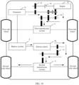
- FIG. 2 shows an example of a schematic diagram of a structure of an electric vehicle drive system according to an embodiment of this application.
- a first powertrain 1 may include a generator 11, an engine 12, a first transmission 13, a second transmission 14, a first clutch 15, and a second clutch 16.
- a second powertrain 2 includes an electric motor 17 and a third transmission 18.
- the first transmission 13, the second transmission 14, the first clutch 15, and the second clutch16 constitute a connection assembly.
- the generator 11 when the first clutch 15 is engaged, the generator 11 is connected to the engine 12. In this case, the engine 12 may drive the generator 11 to generate electric energy, and the generator 11 may output the generated electric energy to a battery system 5.
- the generator 11 When the second clutch 16 is engaged, the generator 11 may be connected to a first transmission system 3, and the generator 11 may drive first-side wheels by using the first transmission system 3.
- the engine 12 When the first clutch 15 and the second clutch 16 are engaged, the engine 12 may be connected to the first transmission system 3, and the engine 12 may drive the first-side wheels by using the first transmission system 3.
- an input shaft of the first transmission 13 is connected to the engine 12 by using the first clutch 15, and an output shaft of the first transmission 13 is connected to the generator 11.
- An input shaft of the second transmission 14 is connected to the generator 11 by using the second clutch 15, and an output shaft of the second transmission 14 is connected to the first transmission system 3.
- An input shaft of the third transmission 18 is connected to the electric motor 17, and an output shaft of the third transmission system 18 is connected to a second transmission system 4. Both the first generator 11 and the electric motor 17 are connected to the battery system 5.
- the first transmission 13 may be a speed reducer, or may be a speed increaser, and both the second transmission 14 and the third transmission 18 are speed reducers. It should be noted that the first transmission 13, the second transmission 14, and the third transmission may be single-speed transmissions, or may be multi-speed transmissions. The first transmission 13, the second transmission 14, and the third transmission may be fixed shaft gear trains or planetary gear trains.
- the first clutch 15 may be a one-way clutch.
- the second clutch 16 may be disposed inside the second transmission 14, and the first clutch 15 may also be disposed inside the first transmission 13. It should be understood that, in this application, the first clutch 15 and the second clutch 16 each may alternatively be replaced by another apparatus with power engagement and disengagement, for example, a synchronizer or a gear sleeve.
- the battery system 5 may output stored electric energy to the electric motor 17, and the electric motor 17 rotates and is driven to the third transmission 18 by using the input shaft of the third transmission 18. Power is output to the output shaft of the third transmission 18 through gear transmission inside the third transmission 18, and is supplied to the electric vehicle for running by using the second transmission system 4. Specifically, for a power transmission path of the electric vehicle, refer to FIG. 3 .
- the battery system 5 may output the stored electric energy to the electric motor 17, and the electric motor 17 rotates and is driven to the third transmission 18 by using the input shaft of the third transmission 18. Power is output to the output shaft of the third transmission 18 through gear transmission inside the third transmission 18, and is supplied to the electric vehicle for running by using the second transmission system 4.
- the second clutch 16 controls the generator 11 to engage with the second transmission 14, and the battery system 5 outputs the stored electric energy to the generator 11.
- the generator 11 rotates as an electric motor and is driven to the second transmission 14 by using the input shaft of the second transmission 14. Power is output to the output shaft of the second transmission 14 through gear transmission inside the second transmission 14, and is supplied to the electric vehicle for running by using the first transmission system 3. Specifically, for a power transmission path of the electric vehicle, refer to FIG. 4 .
- the first clutch 15 controls the engine 12 to engage with the first transmission 13
- the engine 12 drives the generator 11 to rotate
- the generator 11 generates the electric energy and outputs the generated electric energy to the connected battery system 5.
- the battery system 5 outputs the stored electric energy to the electric motor 17, and the electric motor 17 rotates and is driven to the third transmission 18 by using the input shaft of the third transmission 18.
- Power is output to the output shaft of the third transmission 18 through gear transmission inside the third transmission 18, and is supplied to the electric vehicle for running by using the second transmission system 4. Specifically, for a power transmission path of the electric vehicle, refer to FIG. 5 .
- the first clutch 15 controls the engine 12 to engage with the first transmission 13
- the second clutch 16 controls the first transmission 13 to engage with the second transmission 14.
- Power output by the engine 12 is sequentially input to the first transmission 13 and the second transmission 14.
- Power is output to the output shaft of the second transmission 14 through gear transmission inside the first transmission 13 and the second transmission 14, and is supplied to the electric vehicle for running by using the first transmission system 3.
- a power transmission path of the electric vehicle refer to FIG. 6 .
- a shock absorber for example, a torque shock absorber or a dual-mass flywheel, may be further connected between the generator 11 and the first clutch 15.
- a first powertrain 1 may include a generator 21, an engine 22, a first transmission 23, a first clutch 24, and a second clutch 25.
- a second powertrain 2 may include an electric motor 26 and a third transmission 27.
- the first transmission 23, the first clutch 24, and the second clutch 25 constitute a connection assembly.
- the engine 22 is connected to the generator 21 by using the first clutch 24.
- An input shaft of the first transmission 23 is connected to the generator 21 by using the second clutch 25, and an output shaft of the first transmission 23 is connected to the first transmission system 3.
- An input shaft of the third transmission 27 is connected to the electric motor 26, and an output shaft of the third transmission2 is connected to the second transmission system 4. Both the first generator 21 and the electric motor 26 are connected to the battery system 5.
- the engine 22 when the first clutch 24 is engaged, the engine 22 may be connected to the generator 21. In this case, the engine 22 drives the generator 21 to generate electric energy, and the generator 21 may output the generated electric energy to the battery system 5.
- the generator 21 When the second clutch 25 is engaged, the generator 21 may be connected to the first transmission system 3, and the generator 21 may drive the first-side wheels by using the first transmission system 3.
- the engine 22 When the first clutch 24 and the second clutch 25 are engaged, the engine 22 may be connected to the first transmission system 3, and in this case, the engine 22 drives the first-side wheels by using the first transmission system 3.
- FIG. 8 shows an example of a schematic diagram of a structure of an electric vehicle drive system according to an embodiment of this application.
- a first powertrain 1 may include a generator 31, an engine 32, a first transmission 33, a second transmission 34, and a first clutch 35.
- a second powertrain 2 includes an electric motor 36 and a third transmission 37.
- an input shaft of the first transmission 33 is connected to the engine 32 by using the first clutch 35, and an output shaft of the first transmission 33 is connected to the engine 31.
- An input shaft of the second transmission 34 is connected to the generator 31, and an output shaft of the second transmission 34 is connected to a first transmission system 3.
- An input shaft of the third transmission 37 is connected to the electric motor 36, and an output shaft of the third transmission 37 is connected to a second transmission system 4. Both the first generator 31 and the electric motor 36 are connected to a battery system 5.
- the engine 32 when the first clutch 35 is engaged, the engine 32 may be connected to the generator 31. In this case, the engine 32 may drive the generator 31 to generate electric energy, and the generator 31 may output the generated electric energy to the battery system 5.
- the generator 31 When a synchronizer connects the generator 31 to the first transmission system 3, the generator 31 may drive first-side wheels by using the first transmission system 3.
- the engine 32 When the first clutch 35 is engaged and the synchronizer connects the generator 31 to the first transmission system 3, the engine 32 may be connected to the first transmission system 3, and in this case, the engine 32 may drive the first-side wheels by using the first transmission system.
- the first transmission 33 may be a speed reducer or a speed increaser.
- the third transmission 37 is a speed reducer. It should be noted that the first transmission 33 and the third transmission 37 may be single-speed transmissions, or may be multi-speed transmissions.
- the first transmission 33, the second transmission 34, and the third transmission 37 may be fixed shaft gear trains or planetary gear trains.
- a synchronizer is disposed inside the second transmission 34, and coupling teeth of the synchronizer may be disposed on a two-stage transmission gear of the second transmission 34, to implement that the second transmission 34 is in a neutral state.
- the generator 31 is engaged with the first transmission system 3 by using the second transmission 34, and when the second transmission 34 is in the neutral state, engagement between the generator 31 and the first transmission system 3 is cut off.
- the first clutch 35 may be a one-way clutch.
- the first clutch 35 may also be disposed in the first transmission 33. It should be understood that, in this application, the first clutch 15 may alternatively be replaced by another apparatus with power engagement and disengagement, for example, a synchronizer or a gear sleeve.
- the battery system 5 may output stored electric energy to the electric motor 36, and the electric motor 36 rotates and is driven to the third transmission 37 by using the input shaft of the third transmission 37. Power is output to the output shaft of the third transmission 37 through gear transmission inside the third transmission 37, and is supplied to the electric vehicle for running by using the second transmission system 4. Specifically, for a power transmission path of the electric vehicle, refer to FIG. 9 .
- the battery system 5 may output the stored electric energy to the electric motor 36, and the electric motor 36 rotates and is driven to the third transmission 37 by using the input shaft of the third transmission 37.
- Power is output to the output shaft of the third transmission 37 through gear transmission inside the third transmission 37, and is supplied to the electric vehicle for running by using the second transmission system 4.
- the battery system 5 outputs the stored electric energy to the generator 31, and the generator 31 rotates as an electric motor and is driven to the second transmission 34 by using the input shaft of the second transmission 34.
- Power is output to the output shaft of the second transmission 34 through gear transmission inside the second transmission 34, and is supplied to the electric vehicle for running by using the first transmission system 3.
- FIG. 10 for a power transmission path of the electric vehicle, refer to FIG. 10 .
- the first clutch 35 controls the engine 32 to engage with the first transmission 33, the engine 32 drives the generator 31 to rotate, and the generator 31 generates electric energy and outputs the generated electric energy to the connected battery system 5.
- the battery system 5 outputs the stored electric energy to the electric motor 36, and the electric motor 36 rotates and is driven to the third transmission 37 by using the input shaft of the third transmission 37.
- Power is output to the output shaft of the third transmission 37 through gear transmission inside the third transmission 37, and is supplied to the electric vehicle for running by using the second transmission system 4. Specifically, for a power transmission path of the electric vehicle, refer to FIG. 11 .
- the first clutch 35 controls the engine 32 to engage with the first transmission 33, and power output by the engine 32 is sequentially input to the first transmission 33 and the second transmission 34. Power is output to the output shaft of the second transmission 34 through gear transmission inside the first transmission 33 and the second transmission 34, and is supplied to the electric vehicle for running by using the first transmission system 3. Specifically, for a power transmission path of the electric vehicle, refer to FIG. 12 .
- a shock absorber for example, a torque shock absorber or a dual-mass flywheel, may be further connected between the generator 31 and the first clutch 35.
- a first powertrain 1 includes a generator 41, an engine 42, a first transmission 43, and a first clutch 44.
- a second powertrain 2 may include an electric motor 45 and a third transmission 46.
- the first transmission 43 and the first clutch 44 constitute a connection assembly.
- the generator 41 is connected to the engine 42 by using the first clutch 45.
- An input shaft of the first transmission 43 is connected to the generator 41, and an output shaft of the first transmission 43 is connected to the first transmission system 3.
- An input shaft of the third transmission 46 is connected to the electric motor 45, and an output shaft of the third transmission 46 is connected to the second transmission system 4. Both the first generator 41 and the electric motor 45 are connected to the battery system 5.
- the engine 42 when the first clutch 44 is engaged, the engine 42 may be connected to the generator 41. In this case, the engine 42 may drive the generator 41 to generate electric energy, and the generator 41 may output the generated electric energy to the battery system 5.
- the generator 41 When a synchronizer connects the generator 41 to the first transmission system 3, the generator 41 may drive the first-side wheels by using the first transmission system 3.
- the engine 42 When the first clutch 44 is engaged and the synchronizer connects the generator 41 to the first transmission system 3, the engine 42 may be connected to the first transmission system 3, and in this case, the engine 42 may drive the first-side wheels by using the first transmission system 3.
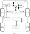
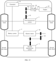
- FIG. 14 shows an example of a schematic diagram of a structure of an electric vehicle drive system according to an embodiment of this application.
- a first powertrain 1 may include a generator 51, an engine 52, a first transmission 53, a second transmission 54, and a dual clutch 55.
- a second powertrain 2 may include an electric motor 56 and a third transmission 57.
- the first transmission 53, the second transmission 54, and the dual clutch 55 constitute a connection assembly.
- the dual clutch 55 includes three ports, namely, a port 551, a port 552, and a port 553.
- an input shaft of the first transmission 53 is connected to the engine 52, and an output shaft of the first transmission 53 is connected to the first output shaft 552 of the dual clutch 55.
- An input shaft of the second transmission 54 is connected to the second output shaft 553 of the dual clutch 55, and an output shaft of the second transmission 54 is connected to a first transmission system 3.
- the input end 551 of the dual clutch 55 is connected to the generator 51.
- An input shaft of the third transmission 57 is connected to the electric motor 56, and an output shaft of the third transmission 57 is connected to a second transmission system 4. Both the first generator 51 and the electric motor 56 are connected to a battery system 5.
- the generator 51 when the port 552 and the port 551 in the dual clutch 55 are engaged, the generator 51 is connected to the engine 52 by using the first transmission 53. In this case, the engine 52 may drive the generator 51 to generate electric energy, and the generator 51 may output the generated electric energy to the battery system 5.
- the generator 51 When the port 552 and the port 553 in the dual clutch 55 are engaged, the generator 51 may be connected to the first transmission system 3 by using the first transmission 53 and the second transmission 54, and the generator 51 may drive first-side wheels by using the first transmission system 3.
- the engine 52 When the port 551 and the port 553 in the dual clutch 55 are engaged, the engine 52 may be connected to the first transmission system 3 by using the second transmission 54, and the engine 52 may drive the first-side wheels by using the first transmission system 3.
- the first transmission 53 may be a speed reducer, or may be a speed increaser, and both the second transmission 54 and the third transmission 57 are speed reducers. It should be noted that the first transmission 53, the second transmission 54, and the third transmission 57 may be single-speed transmissions, or may be multi-speed transmissions. The first transmission 53, the second transmission 54, and the third transmission 57 may be fixed shaft gear trains or planetary gear trains.
- the dual clutch 55 may be disposed in the first transmission 53. It should be understood that the dual clutch 55 in this application may alternatively be replaced by another apparatus with power engagement and disengagement, for example, a synchronizer or a gear sleeve.
- a drive mode of the electric vehicle drive system shown in FIG. 14 is the same as a drive mode shown in FIG. 2 , and is not repeatedly described in this application.
- a shock absorber for example, a torque shock absorber or a dual-mass flywheel, may be further connected between the generator 51 and the dual clutch 55.
- a first powertrain 1 may include a generator 61, an engine 62, a first transmission 63, and a dual clutch 64.
- a second powertrain 2 may include an electric motor 65 and a third transmission 66.
- the first transmission 63 and the dual clutch 64 constitute a connection assembly.
- the dual clutch 64 includes three ports, namely, a port 641, a port 642, and a port 643.
- the generator 61 is connected to the engine 62 by using the dual clutch 64.
- An input shaft of the first transmission 63 is connected to the engine 62 and the generator 61 by using the dual clutch 64, and an output shaft of the first transmission 63 is connected to the first transmission system 3.
- An input shaft of the third transmission 66 is connected to the electric motor 65, and an output shaft of the third transmission 66 is connected to the second transmission system 4. Both the generator 61 and the electric motor 65 are connected to the battery system 5.
- the generator 61 when the port 641 and the port 642 in the dual clutch 64 are engaged, the generator 61 is connected to the engine 62. In this case, the engine 62 may drive the generator 61 to generate electric energy, and the generator 61 may output the generated electric energy to the battery system 5.
- the generator 61 When the port 643 and the port 642 in the dual clutch 64 are engaged, the generator 61 may be connected to the first transmission system 3 by using the first transmission system 63, and the generator 61 may drive the first-side wheels by using the first transmission system 3.
- the engine 62 When the port 641 and the port 643 in the dual clutch 64 are engaged, the engine 62 may be connected to the first transmission system 3 by using the first transmission system 63, and in this case, the engine 62 may drive the first-side wheels by using the first transmission system 3.
- FIG. 16 shows an example of a schematic diagram of a structure of an electric vehicle drive system according to an embodiment of this application.
- a first powertrain 1 may include a generator 71, an engine 72, a first transmission 73, a second transmission 74, and a synchronizer 75.
- a second powertrain 2 may include an electric motor 76 and a third transmission 77.
- the first transmission 73, the second transmission 74 and the synchronizer 75 constitute a connection assembly.
- coupling teeth of the synchronizer 75 are separately connected to an output shaft of the first transmission 73 and an input shaft of the second transmission 74, and a gear hub of the synchronizer 75 is connected to the generator 11.
- An input shaft of the first transmission 73 is connected to the engine 72.
- the input shaft of the second transmission 74 is connected to the generator 71, and an output shaft of the second transmission 74 is connected to a first transmission system 3.
- An input shaft of the third transmission 77 is connected to the electric motor 76, and an output shaft of the third transmission 77 is connected to a second transmission system 4. Both the first generator 71 and the electric motor 76 are connected to a battery system 5.
- the synchronizer 75 when the synchronizer 75 connects the engine 72 to the generator 71, the engine 72 may drive the generator 71 to generate electric energy, and the generator 71 may output the generated electric energy to the battery system 5.
- the generator 71 drives first-side wheels by using the first transmission system 3.
- the first transmission 73 may be a speed reducer, or may be a speed increaser, and both the second transmission 74 and the third transmission 77 are speed reducers. It should be noted that the first transmission 73, the second transmission 74, and the third transmission 77 may be single-speed transmissions, or may be multi-speed transmissions. The first transmission 73, the second transmission 74, and the third transmission 77 may be fixed shaft gear trains or planetary gear trains.
- the battery system 5 may output stored electric energy to the electric motor 76, and the electric motor 76 rotates and is driven to the third transmission 77 by using the input shaft of the third transmission 77. Power is output to the output shaft of the third transmission 77 through gear transmission inside the third transmission 77, and is supplied to the electric vehicle for running by using the second transmission system 4. Specifically, for a power transmission path of the electric vehicle, refer to FIG. 17 .
- the battery system 5 may output the stored electric energy to the electric motor 76, and the electric motor 76 rotates and is driven to the third transmission 77 by using the input shaft of the third transmission 77. Power is output to the output shaft of the third transmission 77 through gear transmission inside the third transmission 77, and is supplied to the electric vehicle for running by using the second transmission system 4. At the same time, the battery system 5 outputs the stored electric energy to the generator 71, and the synchronizer 75 is in transmission connection to a gear inside the second transmission 74.
- the generator 71 rotates as a motor and is driven to the second transmission 74 by using the input shaft of the second transmission 74. Power is output to the output shaft of the second transmission 74 through gear transmission inside the second transmission 74, and is supplied to the electric vehicle for running by using the first transmission system 3. Specifically, for a power transmission path of the electric vehicle, refer to FIG. 18 .
- the synchronizer 75 controls the engine 72 to engage with the generator 71, the engine 72 drives the generator 71 to rotate, and the generator 71 generates electric energy and outputs the generated electric energy to the connected battery system 5.
- the battery system 5 outputs the stored electric energy to the electric motor 76, and the electric motor 76 rotates and is driven to the third transmission 77 by using the input shaft of the third transmission 77.
- Power is output to the output shaft of the third transmission 77 through gear transmission inside the third transmission 77, and is supplied to the electric vehicle for running by using the second transmission system 4. Specifically, for a power transmission path of the electric vehicle, refer to FIG. 19 .
- a shock absorber for example, a torque shock absorber or a dual-mass flywheel, may be further connected between the generator 71 and the synchronizer 75.
- a first powertrain 1 may include a generator 81, an engine 82, a first transmission 83, and a synchronizer 84.
- a second powertrain 2 includes an electric motor 85 and a third transmission 86.
- the first transmission 83 and the synchronizer 84 constitute a connection assembly.
- coupling teeth of the synchronizer 84 are separately connected to an input shaft of the first transmission 83 and the engine 82, and a gear hub of the synchronizer 84 is connected to the generator 81.
- the input shaft of the first transmission 83 is connected to the generator 81, and an output shaft of the first transmission 83 is connected to the first transmission system 3.
- An input shaft of the third transmission 86 is connected to the electric motor 85, and an output shaft of the third transmission 86 is connected to the second transmission system 4. Both the first generator 81 and the electric motor 85 are connected to the battery system 5.
- the synchronizer 84 when the synchronizer 84 connects the engine 82 to the generator 81, the engine 82 may drive the generator 81 to generate electric energy, and the generator 81 may output the generated electric energy to the battery system 5.
- the generator 81 may drive the first-side wheels by using the first transmission system 3.
- a drive mode of the electric vehicle drive system shown in FIG. 20 is the same as the drive mode shown in FIG. 16 , and is not repeatedly described in this application.
- the electric vehicle includes wheels, first-side wheels, second-side wheels, and the electric vehicle drive system in any one of the foregoing solutions.
- a generator may be used as an electric motor to drive the electric vehicle, to implement generator reuse, so that a separate motor does not need to be configured, a quantity of components in the electric vehicle drive system is reduced, driving costs of the electric vehicle are reduced, and available space for passengers is increased.
Landscapes
- Engineering & Computer Science (AREA)
- Chemical & Material Sciences (AREA)
- Combustion & Propulsion (AREA)
- Transportation (AREA)
- Mechanical Engineering (AREA)
- Electric Propulsion And Braking For Vehicles (AREA)
- Hybrid Electric Vehicles (AREA)
Applications Claiming Priority (1)
| Application Number | Priority Date | Filing Date | Title |
|---|---|---|---|
| PCT/CN2021/107181 WO2023000144A1 (zh) | 2021-07-19 | 2021-07-19 | 电动汽车驱动系统和电动汽车 |
Publications (3)
| Publication Number | Publication Date |
|---|---|
| EP4364989A1 true EP4364989A1 (de) | 2024-05-08 |
| EP4364989A4 EP4364989A4 (de) | 2024-08-21 |
| EP4364989B1 EP4364989B1 (de) | 2025-10-01 |
Family
ID=83018518
Family Applications (1)
| Application Number | Title | Priority Date | Filing Date |
|---|---|---|---|
| EP21950410.7A Active EP4364989B1 (de) | 2021-07-19 | 2021-07-19 | Antriebssystem für elektrofahrzeug und elektrofahrzeug |
Country Status (4)
| Country | Link |
|---|---|
| US (1) | US20240149859A1 (de) |
| EP (1) | EP4364989B1 (de) |
| CN (1) | CN115003531B (de) |
| WO (1) | WO2023000144A1 (de) |
Families Citing this family (3)
| Publication number | Priority date | Publication date | Assignee | Title |
|---|---|---|---|---|
| US12221013B2 (en) * | 2022-09-22 | 2025-02-11 | Arvinmeritor Technology, Llc | Vehicle drive axle system and method of control |
| WO2025252899A1 (en) * | 2024-06-05 | 2025-12-11 | Schaeffler Technologies AG & Co. KG | Vehicle generator module with transmission |
| WO2025252455A1 (en) * | 2024-06-05 | 2025-12-11 | Schaeffler Technologies AG & Co. KG | Vehicle generator module with transmission |
Family Cites Families (19)
| Publication number | Priority date | Publication date | Assignee | Title |
|---|---|---|---|---|
| WO2009056042A1 (fr) * | 2007-10-22 | 2009-05-07 | Byd Company Limited | Système d'entraînement hybride et son procédé d'entraînement |
| JP2009143263A (ja) * | 2007-12-11 | 2009-07-02 | Mazda Motor Corp | 車両用駆動制御装置 |
| JP5136660B2 (ja) * | 2010-07-08 | 2013-02-06 | 株式会社デンソー | 車両用動力伝達装置 |
| KR101261955B1 (ko) * | 2011-11-10 | 2013-05-09 | 현대자동차주식회사 | 하이브리드 차량용 시스템 |
| KR101519807B1 (ko) * | 2012-03-26 | 2015-05-12 | 도요타지도샤가부시키가이샤 | 차량의 제어 장치 |
| CN203186120U (zh) * | 2013-03-14 | 2013-09-11 | 吉林大学 | 增程式电动汽车动力系统 |
| CN203293890U (zh) * | 2013-06-03 | 2013-11-20 | 深圳中德世纪新能源有限公司 | 混合动力汽车传动系统 |
| CN104290586B (zh) * | 2014-01-30 | 2015-09-02 | 比亚迪股份有限公司 | 用于车辆的动力传动系统及具有其的车辆 |
| US10670123B2 (en) * | 2014-01-30 | 2020-06-02 | Byd Company Limited | Power transmission system for vehicle and vehicle comprising the same |
| CN104279311B (zh) * | 2014-01-30 | 2015-11-25 | 比亚迪股份有限公司 | 车辆中同步器的控制方法及车辆 |
| US9568080B2 (en) * | 2014-01-30 | 2017-02-14 | Byd Company Limited | Power transmission system for vehicle and vehicle comprising the same |
| CN104276031B (zh) * | 2014-01-30 | 2016-01-13 | 比亚迪股份有限公司 | 车辆及其驱动控制方法 |
| WO2015125407A1 (ja) * | 2014-02-20 | 2015-08-27 | パナソニックIpマネジメント株式会社 | 車両用ハイブリッドシステム |
| JP6524453B2 (ja) * | 2015-09-30 | 2019-06-05 | ジヤトコ株式会社 | パワートレーン |
| CN208134080U (zh) * | 2016-12-21 | 2018-11-23 | 舍弗勒技术股份两合公司 | 驱动装置和机动车 |
| CN110962572B (zh) * | 2018-09-29 | 2021-05-14 | 比亚迪股份有限公司 | 混合动力驱动系统及车辆 |
| DE102018132150A1 (de) * | 2018-12-13 | 2020-06-18 | Schaeffler Technologies AG & Co. KG | Hybridantriebsstrang mit zwei Elektromotoren und Allradantriebsmöglichkeit |
| DE102019119459A1 (de) * | 2019-07-18 | 2021-01-21 | Bayerische Motoren Werke Aktiengesellschaft | Getriebebaugruppe, Antriebseinheit, Verfahren zum Betrieb einer Antriebseinheit sowie Antriebsstrang |
| CN110949114A (zh) * | 2019-11-15 | 2020-04-03 | 华为技术有限公司 | 减速器、电动汽车的驱动系统及电动汽车 |
-
2021
- 2021-07-19 EP EP21950410.7A patent/EP4364989B1/de active Active
- 2021-07-19 WO PCT/CN2021/107181 patent/WO2023000144A1/zh not_active Ceased
- 2021-07-19 CN CN202180008020.1A patent/CN115003531B/zh active Active
-
2024
- 2024-01-17 US US18/415,479 patent/US20240149859A1/en active Pending
Also Published As
| Publication number | Publication date |
|---|---|
| US20240149859A1 (en) | 2024-05-09 |
| EP4364989A4 (de) | 2024-08-21 |
| WO2023000144A1 (zh) | 2023-01-26 |
| CN115003531B (zh) | 2026-04-14 |
| EP4364989B1 (de) | 2025-10-01 |
| CN115003531A (zh) | 2022-09-02 |
Similar Documents
| Publication | Publication Date | Title |
|---|---|---|
| CN101244687B (zh) | 混联式混合动力驱动系统及其驱动方法 | |
| US20240149859A1 (en) | Electric vehicle drive system and electric vehicle | |
| EP2117868B1 (de) | Hybridantriebsstrang | |
| CN111098695B (zh) | 混合动力驱动系统及车辆 | |
| CN210526287U (zh) | 两档混合动力耦合系统及车辆 | |
| CN111361406B (zh) | 一种汽车混合动力系统的控制方法 | |
| CN210454447U (zh) | 一种双离合器控制的平行轴式混合动力系统 | |
| CN105667295A (zh) | 集成式双转子电机的两挡混合动力汽车驱动系统 | |
| CN110816253B (zh) | 无齿圈行星轮系混合动力系统 | |
| CN210706870U (zh) | 一种混合动力汽车用动力驱动系统 | |
| CN111114279A (zh) | 混合动力驱动系统及车辆 | |
| CN219969391U (zh) | 车辆的动力系统和车辆 | |
| CN110303874B (zh) | 一种功率分流-合流式混合动力变速器 | |
| CN205601593U (zh) | 两挡混合动力系统及混合动力汽车 | |
| CN215904302U (zh) | 混合驱动系统及其车辆 | |
| CN114953961B (zh) | 混合动力耦合机构及车辆 | |
| CN111791688B (zh) | 混合动力机电耦合系统和车辆 | |
| CN110789328B (zh) | 混合动力驱动系统 | |
| CN210760230U (zh) | 一种用于混合动力车辆的混合动力变速器 | |
| CN210617837U (zh) | 混合动力汽车用动力驱动系统 | |
| CN221737603U (zh) | 车辆混动驱动系统及车辆 | |
| CN214295552U (zh) | 多模式切换的混合动力机电耦合系统和车辆 | |
| CN212313268U (zh) | 混合动力机电耦合系统和车辆 | |
| CN213082903U (zh) | 混合动力机电耦合系统和车辆 | |
| CN101462482A (zh) | 新型双电机混联混合动力总成构型 |
Legal Events
| Date | Code | Title | Description |
|---|---|---|---|
| STAA | Information on the status of an ep patent application or granted ep patent |
Free format text: STATUS: THE INTERNATIONAL PUBLICATION HAS BEEN MADE |
|
| PUAI | Public reference made under article 153(3) epc to a published international application that has entered the european phase |
Free format text: ORIGINAL CODE: 0009012 |
|
| STAA | Information on the status of an ep patent application or granted ep patent |
Free format text: STATUS: REQUEST FOR EXAMINATION WAS MADE |
|
| 17P | Request for examination filed |
Effective date: 20240201 |
|
| AK | Designated contracting states |
Kind code of ref document: A1 Designated state(s): AL AT BE BG CH CY CZ DE DK EE ES FI FR GB GR HR HU IE IS IT LI LT LU LV MC MK MT NL NO PL PT RO RS SE SI SK SM TR |
|
| A4 | Supplementary search report drawn up and despatched |
Effective date: 20240718 |
|
| RIC1 | Information provided on ipc code assigned before grant |
Ipc: B60W 20/00 20160101ALI20240712BHEP Ipc: B60W 10/08 20060101ALI20240712BHEP Ipc: B60K 6/38 20071001ALI20240712BHEP Ipc: B60K 6/36 20071001AFI20240712BHEP |
|
| DAV | Request for validation of the european patent (deleted) | ||
| DAX | Request for extension of the european patent (deleted) | ||
| GRAP | Despatch of communication of intention to grant a patent |
Free format text: ORIGINAL CODE: EPIDOSNIGR1 |
|
| STAA | Information on the status of an ep patent application or granted ep patent |
Free format text: STATUS: GRANT OF PATENT IS INTENDED |
|
| INTG | Intention to grant announced |
Effective date: 20250522 |
|
| GRAS | Grant fee paid |
Free format text: ORIGINAL CODE: EPIDOSNIGR3 |
|
| GRAA | (expected) grant |
Free format text: ORIGINAL CODE: 0009210 |
|
| STAA | Information on the status of an ep patent application or granted ep patent |
Free format text: STATUS: THE PATENT HAS BEEN GRANTED |
|
| AK | Designated contracting states |
Kind code of ref document: B1 Designated state(s): AL AT BE BG CH CY CZ DE DK EE ES FI FR GB GR HR HU IE IS IT LI LT LU LV MC MK MT NL NO PL PT RO RS SE SI SK SM TR |
|
| REG | Reference to a national code |
Ref country code: GB Ref legal event code: FG4D Ref country code: CH Ref legal event code: F10 Free format text: ST27 STATUS EVENT CODE: U-0-0-F10-F00 (AS PROVIDED BY THE NATIONAL OFFICE) Effective date: 20251001 |
|
| REG | Reference to a national code |
Ref country code: IE Ref legal event code: FG4D |
|
| REG | Reference to a national code |
Ref country code: DE Ref legal event code: R096 Ref document number: 602021039868 Country of ref document: DE |
|
| REG | Reference to a national code |
Ref country code: NL Ref legal event code: MP Effective date: 20251001 |
|
| REG | Reference to a national code |
Ref country code: AT Ref legal event code: MK05 Ref document number: 1842197 Country of ref document: AT Kind code of ref document: T Effective date: 20251001 |
|
| PG25 | Lapsed in a contracting state [announced via postgrant information from national office to epo] |
Ref country code: NL Free format text: LAPSE BECAUSE OF FAILURE TO SUBMIT A TRANSLATION OF THE DESCRIPTION OR TO PAY THE FEE WITHIN THE PRESCRIBED TIME-LIMIT Effective date: 20251001 |
|
| PG25 | Lapsed in a contracting state [announced via postgrant information from national office to epo] |
Ref country code: ES Free format text: LAPSE BECAUSE OF FAILURE TO SUBMIT A TRANSLATION OF THE DESCRIPTION OR TO PAY THE FEE WITHIN THE PRESCRIBED TIME-LIMIT Effective date: 20251001 |
|
| REG | Reference to a national code |
Ref country code: LT Ref legal event code: MG9D |
|
| PG25 | Lapsed in a contracting state [announced via postgrant information from national office to epo] |
Ref country code: NO Free format text: LAPSE BECAUSE OF FAILURE TO SUBMIT A TRANSLATION OF THE DESCRIPTION OR TO PAY THE FEE WITHIN THE PRESCRIBED TIME-LIMIT Effective date: 20260101 |
|
| PG25 | Lapsed in a contracting state [announced via postgrant information from national office to epo] |
Ref country code: HR Free format text: LAPSE BECAUSE OF FAILURE TO SUBMIT A TRANSLATION OF THE DESCRIPTION OR TO PAY THE FEE WITHIN THE PRESCRIBED TIME-LIMIT Effective date: 20251001 Ref country code: AT Free format text: LAPSE BECAUSE OF FAILURE TO SUBMIT A TRANSLATION OF THE DESCRIPTION OR TO PAY THE FEE WITHIN THE PRESCRIBED TIME-LIMIT Effective date: 20251001 Ref country code: FI Free format text: LAPSE BECAUSE OF FAILURE TO SUBMIT A TRANSLATION OF THE DESCRIPTION OR TO PAY THE FEE WITHIN THE PRESCRIBED TIME-LIMIT Effective date: 20251001 |
|
| PG25 | Lapsed in a contracting state [announced via postgrant information from national office to epo] |
Ref country code: RS Free format text: LAPSE BECAUSE OF FAILURE TO SUBMIT A TRANSLATION OF THE DESCRIPTION OR TO PAY THE FEE WITHIN THE PRESCRIBED TIME-LIMIT Effective date: 20260101 |
|
| PG25 | Lapsed in a contracting state [announced via postgrant information from national office to epo] |
Ref country code: IS Free format text: LAPSE BECAUSE OF FAILURE TO SUBMIT A TRANSLATION OF THE DESCRIPTION OR TO PAY THE FEE WITHIN THE PRESCRIBED TIME-LIMIT Effective date: 20260201 |
|
| PG25 | Lapsed in a contracting state [announced via postgrant information from national office to epo] |
Ref country code: PT Free format text: LAPSE BECAUSE OF FAILURE TO SUBMIT A TRANSLATION OF THE DESCRIPTION OR TO PAY THE FEE WITHIN THE PRESCRIBED TIME-LIMIT Effective date: 20260202 Ref country code: CZ Free format text: LAPSE BECAUSE OF FAILURE TO SUBMIT A TRANSLATION OF THE DESCRIPTION OR TO PAY THE FEE WITHIN THE PRESCRIBED TIME-LIMIT Effective date: 20251001 |
|
| PG25 | Lapsed in a contracting state [announced via postgrant information from national office to epo] |
Ref country code: PL Free format text: LAPSE BECAUSE OF FAILURE TO SUBMIT A TRANSLATION OF THE DESCRIPTION OR TO PAY THE FEE WITHIN THE PRESCRIBED TIME-LIMIT Effective date: 20251001 |
|
| PG25 | Lapsed in a contracting state [announced via postgrant information from national office to epo] |
Ref country code: LV Free format text: LAPSE BECAUSE OF FAILURE TO SUBMIT A TRANSLATION OF THE DESCRIPTION OR TO PAY THE FEE WITHIN THE PRESCRIBED TIME-LIMIT Effective date: 20251001 |