EP4365065A1 - Longeron latéral pour véhicule - Google Patents
Longeron latéral pour véhicule Download PDFInfo
- Publication number
- EP4365065A1 EP4365065A1 EP22833497.5A EP22833497A EP4365065A1 EP 4365065 A1 EP4365065 A1 EP 4365065A1 EP 22833497 A EP22833497 A EP 22833497A EP 4365065 A1 EP4365065 A1 EP 4365065A1
- Authority
- EP
- European Patent Office
- Prior art keywords
- side sill
- frame
- reinforcing frame
- vehicle
- attached
- Prior art date
- Legal status (The legal status is an assumption and is not a legal conclusion. Google has not performed a legal analysis and makes no representation as to the accuracy of the status listed.)
- Pending
Links
- 230000003014 reinforcing effect Effects 0.000 claims abstract description 130
- 229910000831 Steel Inorganic materials 0.000 claims description 14
- 239000010959 steel Substances 0.000 claims description 14
- 238000005452 bending Methods 0.000 claims description 7
- 238000003466 welding Methods 0.000 claims description 6
- 239000000853 adhesive Substances 0.000 claims description 3
- 230000001070 adhesive effect Effects 0.000 claims description 3
- 238000010521 absorption reaction Methods 0.000 description 9
- 238000006073 displacement reaction Methods 0.000 description 8
- 239000000463 material Substances 0.000 description 7
- XAGFODPZIPBFFR-UHFFFAOYSA-N aluminium Chemical compound [Al] XAGFODPZIPBFFR-UHFFFAOYSA-N 0.000 description 6
- 229910052782 aluminium Inorganic materials 0.000 description 6
- 238000000465 moulding Methods 0.000 description 5
- 238000004519 manufacturing process Methods 0.000 description 4
- 230000008878 coupling Effects 0.000 description 2
- 238000010168 coupling process Methods 0.000 description 2
- 238000005859 coupling reaction Methods 0.000 description 2
- 230000007423 decrease Effects 0.000 description 2
- 238000012986 modification Methods 0.000 description 2
- 230000004048 modification Effects 0.000 description 2
- 239000013585 weight reducing agent Substances 0.000 description 2
- 229910000794 TRIP steel Inorganic materials 0.000 description 1
- 229910000797 Ultra-high-strength steel Inorganic materials 0.000 description 1
- 238000007792 addition Methods 0.000 description 1
- 238000002485 combustion reaction Methods 0.000 description 1
- 238000012217 deletion Methods 0.000 description 1
- 230000037430 deletion Effects 0.000 description 1
- 230000000694 effects Effects 0.000 description 1
- 238000005516 engineering process Methods 0.000 description 1
- 238000001125 extrusion Methods 0.000 description 1
- 239000006260 foam Substances 0.000 description 1
Images



Classifications
-
- B—PERFORMING OPERATIONS; TRANSPORTING
- B62—LAND VEHICLES FOR TRAVELLING OTHERWISE THAN ON RAILS
- B62D—MOTOR VEHICLES; TRAILERS
- B62D21/00—Understructures, i.e. chassis frame on which a vehicle body may be mounted
- B62D21/15—Understructures, i.e. chassis frame on which a vehicle body may be mounted having impact absorbing means, e.g. a frame designed to permanently or temporarily change shape or dimension upon impact with another body
- B62D21/157—Understructures, i.e. chassis frame on which a vehicle body may be mounted having impact absorbing means, e.g. a frame designed to permanently or temporarily change shape or dimension upon impact with another body for side impacts
-
- B—PERFORMING OPERATIONS; TRANSPORTING
- B62—LAND VEHICLES FOR TRAVELLING OTHERWISE THAN ON RAILS
- B62D—MOTOR VEHICLES; TRAILERS
- B62D21/00—Understructures, i.e. chassis frame on which a vehicle body may be mounted
- B62D21/15—Understructures, i.e. chassis frame on which a vehicle body may be mounted having impact absorbing means, e.g. a frame designed to permanently or temporarily change shape or dimension upon impact with another body
-
- B—PERFORMING OPERATIONS; TRANSPORTING
- B62—LAND VEHICLES FOR TRAVELLING OTHERWISE THAN ON RAILS
- B62D—MOTOR VEHICLES; TRAILERS
- B62D25/00—Superstructure or monocoque structure sub-units; Parts or details thereof not otherwise provided for
- B62D25/02—Side panels
- B62D25/025—Side sills thereof
-
- B—PERFORMING OPERATIONS; TRANSPORTING
- B62—LAND VEHICLES FOR TRAVELLING OTHERWISE THAN ON RAILS
- B62D—MOTOR VEHICLES; TRAILERS
- B62D27/00—Connections between superstructure or understructure sub-units
- B62D27/02—Connections between superstructure or understructure sub-units rigid
- B62D27/023—Assembly of structural joints
-
- B—PERFORMING OPERATIONS; TRANSPORTING
- B62—LAND VEHICLES FOR TRAVELLING OTHERWISE THAN ON RAILS
- B62D—MOTOR VEHICLES; TRAILERS
- B62D27/00—Connections between superstructure or understructure sub-units
- B62D27/02—Connections between superstructure or understructure sub-units rigid
- B62D27/026—Connections by glue bonding
-
- B—PERFORMING OPERATIONS; TRANSPORTING
- B60—VEHICLES IN GENERAL
- B60Y—INDEXING SCHEME RELATING TO ASPECTS CROSS-CUTTING VEHICLE TECHNOLOGY
- B60Y2304/00—Optimising design; Manufacturing; Testing
- B60Y2304/03—Reducing weight
-
- B—PERFORMING OPERATIONS; TRANSPORTING
- B60—VEHICLES IN GENERAL
- B60Y—INDEXING SCHEME RELATING TO ASPECTS CROSS-CUTTING VEHICLE TECHNOLOGY
- B60Y2304/00—Optimising design; Manufacturing; Testing
- B60Y2304/05—Reducing production costs, e.g. by redesign
-
- B—PERFORMING OPERATIONS; TRANSPORTING
- B60—VEHICLES IN GENERAL
- B60Y—INDEXING SCHEME RELATING TO ASPECTS CROSS-CUTTING VEHICLE TECHNOLOGY
- B60Y2306/00—Other features of vehicle sub-units
- B60Y2306/01—Reducing damages in case of crash, e.g. by improving battery protection
Definitions
- the present disclosure relates to a side sill for a vehicle.
- a side sill for a vehicle serves to protect passengers by absorbing collision energy in the event of a side collision.
- a side sill applied to eco-friendly vehicles such as electric vehicles serves to protect not only passengers but also batteries disposed on a floor. Because the battery has a relatively large volume as compared to other components of the vehicle, a side space of a vehicle equipped with the battery is relatively narrow as compared to a vehicle equipped with an internal combustion engine.
- the side sill applied to the eco-friendly vehicles needs to be capable of absorbing maximum collision energy in a narrow space, and needs to have a minimum weight in order to improve energy efficiency of eco-friendly vehicles.
- Patent Document 1 KR 20-1998-0043143U (September 25, 1998 )
- An aspect of the present disclosure is to improve collision energy absorption efficiency of a side sill and achieve lightweightedness thereof.
- An aspect of the present disclosure is to increase the rigidity of a side sill and reduce manufacturing costs.
- a side sill for a vehicle may include: a side sill frame formed to have a hollow portion; a first reinforcing frame disposed in the hollow portion and attached to the side sill; a second reinforcing frame disposed in the hollow portion and attached to the first reinforcing frame and the side sill frame, wherein the first reinforcing frame and the second reinforcing frame may be disposed in the hollow portion so as to form a closed cross-section in the hollow portion from a thickness-wise cross-section of the side sill frame.
- At least one of the side sill frame, the first reinforcing frame, and the second reinforcing frame may be formed of steel.
- first reinforcing frame and the second reinforcing frame may include a concave-convex portion in a longitudinal cross-sectional shape of the side sill frame.
- first reinforcing frame and the second reinforcing frame may overlap each other in the hollow portion.
- a convex portion and a concave portion may be formed continuously in a longitudinal direction of the side sill frame.
- the convex portion of the first reinforcing frame may overlap the convex portion of the second reinforcing frame, and the concave portion of the first reinforcing frame may overlap the concave portion of the second reinforcing frame.
- the side sill frame may include: a first side sill frame to which the first reinforcing frame is attached; and a second side sill frame attached to the first side sill frame and having an internal surface to which the second reinforcing frame is attached.
- a shape of a thickness-wise cross-section of the first reinforcing frame may include: a plurality of first lower flange portions formed by bending both ends and attached to an internal surface of the first side sill frame; a plurality of first extension portions connected to the plurality of first lower flange portions, respectively, and extending in a direction of the second reinforcing frame; and a first upper flange portion connected to the plurality of first extension portions.
- a shape of a thickness-wise cross-section of the second reinforcing frame may include: a plurality of second extension portions attached to the first extension portion and extending in a direction of the second side sill frame; and a second upper flange portion connected to the second extension portion and attached to an internal surface of the second side sill frame.
- the second upper flange portion may be planar.
- the second extension portion may have a step portion.
- a width from an end of the second extension portion on one side to an end of the second extension portion on the other side is the widest.
- end of the second extension portion may exist on the first extension portion.
- first lower flange portion may be attached to the first side sill frame by welding
- second extension portion may be attached to the first extension portion by the welding
- second upper flange portion may be attached to the second side sill frame with an adhesive
- collision energy absorption efficiency of a side sill may be improved, and a weight of the side sill may be reduced.
- the rigidity of a side sill may be increased, and manufacturing costs may be reduced.
- an X-axis illustrated in the accompanying drawings is a width direction of the side sill
- a Y-axis is a length direction of the side sill
- a Z-axis is a height direction of the side sill.
- a side sill for a vehicle 100 may include a side sill frame 110 having a hollow portion 111, a first reinforcing frame 120 disposed in the hollow portion 111, and a second reinforcing frame 130 disposed in the hollow portion 111.
- the first reinforcing frame 120 may be attached to the side sill frame 110 and fixed to the hollow portion 111.
- the second reinforcing frame 130 may be attached to the first reinforcing frame 120 and the side sill frame 110 and fixed to the hollow portion 111.
- the first reinforcing frame 120 and the second reinforcing frame 130 may form a closed cross-section in the hollow portion 111 in a thickness-wise cross-section of the side sill frame.
- the side sill frame 110 may include a first side sill frame 112 attached to the first reinforcing frame 120 and a second side sill frame 113 attached to the first side sill frame 112 so as to form an attachment portion with the first side sill frame 112.
- At least one of the first side sill frame 112, the second side sill frame 113, the first reinforcing frame 120, and the second reinforcing frame 130 may be formed of steel. Accordingly, a mechanical strength of the side sill for a vehicle may be improved.
- the second reinforcing frame 130 may be attached to an internal surface of the second side sill frame 113.
- the first reinforcing frame 120 and the second reinforcing frame 130 may be attached to the first side sill frame 112 and the second side sill frame 113 so as to be disposed in parallel with the X-axis, respectively.
- An internal surface of the second reinforcing frame 130 may be attached to an external surface of the first reinforcing frame 120. Accordingly, the first reinforcing frame 120 and the second reinforcing frame 130 may overlap each other in the hollow portion.
- the hollow portion may be a closed cross-section. Accordingly, when an impact is applied in an X-axis direction, a capacity to absorb collision energy may be improved.
- first side sill frame 112, the second side sill frame 113, the first reinforcing frame 120, and the second reinforcing frame 130 in the present disclosure may further improve the capacity to absorb collision energy than the first side sill frame 112, the second side sill frame 113, the first reinforcing frame 120, and the second reinforcing frame 130, formed of aluminum of the same weight.
- a side sill for a vehicle made of aluminum an increase in a load of an entire vehicle may be prevented, and a side sill for a vehicle with more improved collision energy absorption capacity than the side sill for a vehicle formed of aluminum may be implemented at the same time.
- the first reinforcing frame 120 and the second reinforcing frame 130 may be formed of a material including ultra-high strength steel with a tensile strength of 980 MPa or higher.
- the first reinforcing frame 120 and the second reinforcing frame 130 may be formed of a material including 1180 TRIP steel.
- the first side sill frame 112 and the second side sill frame 113 may be formed of a material including 1470 MART steel.
- the material is not necessarily limited by the present disclosure, and may be appropriately changed and applied within the scope of the steel material.
- At least one of the first side sill frame 112, the second side sill frame 113, the first reinforcing frame 120, and the second reinforcing frame 130 may be molded by foam forming or crash forming a steel plate. This may contribute to reducing manufacturing costs through reduction of molding costs.
- first side sill frame 112 the second side sill frame 113, the first reinforcing frame 120, and the second reinforcing frame 130 are disposed as illustrated in FIG. 2 and coupled to each other, a closed cross section in a direction in parallel with the X-axis may be easily formed. Accordingly, assembly and production efficiency of the side sill for a vehicle may be improved.
- the side sill for a vehicle when the side sill for a vehicle receives an impact from a side surface thereof, that is, in the X-axis direction, the side sill for a vehicle may be uniformly deformed in the Z-axis direction.
- first reinforcing frame 120 and the second reinforcing frame 130 may be prevented from showing uneven deformation behavior in the Z-axis direction, and may be normally compressed and deformed in the X-axis direction.
- a collision energy absorption capacity thereof may be at least equal to or greater than a collision energy absorption capacity of the vehicle side sill formed of aluminum of the same weight. Accordingly, as compared to when the side sill is formed of aluminum, the side sill formed of steel may improve the collision energy absorption efficiency to equal or higher levels while lightening the side sill.
- the first reinforcing frame 120 may be provided such that the cross-sectional shape in the Y-axis direction includes a concave-convex portion 140.
- the second reinforcing frame 130 may be provided such that the cross-sectional shape in the Y-axis direction includes a concave-convex portion 140.
- the concave-convex portion 140 may be formed by continuing a convex portion 141 and a concave portion 142 in the Y-axis direction.
- the convex portion 141 and the concave 142 may be continuously provided during a predetermined section in the Y-axis direction.
- rigidity may be increased without increasing a weight of the first reinforcing frame 120 and the second reinforcing frame 130.
- Lengths of the convex portion 141 and the concave portion 142 in the Y-axis direction and lengths thereof in the Z-axis direction are not necessarily limited by the present disclosure, and may be determined in consideration of at least one of the type and thickness of the steel applied to the first reinforcing frame 120 and the second reinforcing frame 130, and may be determined in consideration of at least one of at least one element among the type and thickness of a steel material applied to the first reinforcing frame 120 and the second reinforcing frame 130, and may be determined by the specifications required as a side sill for a vehicle.
- the first reinforcing frame 120 and the second reinforcing frame 130 may overlap each other in the hollow portion.
- a region in which the first reinforcing frame 120 and the second reinforcing frame 130 overlap each other may be an overlapping portion 150.
- the overlapping portion 150 may be continuous in the Y-axis direction.
- a separate coupling member for assembling the first reinforcing frame 120 and the second reinforcing frame 130 within the hollow portion 111 becomes unnecessary, and a degree of design freedom may be improved.
- a first convex portion 141a formed in the first reinforcing frame 120 may overlap a second convex portion 141b formed in the second reinforcing frame 130, and a first concave portion 142a formed in the first reinforcing frame 120 may overlap a second concave portion 142b formed in the second reinforcing frame 130.
- FIG. 7 illustrates a first reinforcing frame 120 according to an example embodiment of the present disclosure.
- the first reinforcing frame 120 may be formed by bending and molding a single steel plate. By bending and molding the single steel plate, a mechanical strength of the first reinforcing frame 120 may be further improved.
- a shape of a thickness-wise cross-section of the first reinforcing frame 120 may include a plurality of first lower flange portion 122 formed by bending both ends 121 and attached to an internal surface of the first side sill frame 112 (see FIG. 5 ), a plurality of first extension portions 123 connected to the plurality of first lower flange portions 122 and extending in a direction of the second reinforcing frame 130 (see FIG. 5 ), respectively, and the first upper flange portion 124 connected to the plurality of first extension portions 123.
- the first reinforcing frame 120 may be bent and molded such that the first extension portion 123 and the first lower flange portion 122 may be disposed to cross each other.
- the first lower flange portion 122 may be attached to the internal surface of the first side sill frame 112 (see FIG. 5 ) by welding.
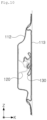
- FIG. 8 illustrates a second reinforcing frame 130 according to an example embodiment of the present disclosure.
- the second reinforcing frame 130 may be formed by bending and molding the single steel plate. By bending and molding the single steel plate, the mechanical strength of the second reinforcing frame 130 may be further improved.
- the second reinforcing frame 130 may be molded such that a shape of a thickness-wise cross-section thereof has a shape in which both ends 131 face each other in the Z-axis direction. Furthermore, the second reinforcing frame 130 may include a plurality of second extension portions 132 extending in a direction of the second side sill frame 113 (see FIG. 5 ), and may include a second upper flange portion 133 connected to the plurality of second extension portions 132 and attached to the internal surface of the second side sill frame 113 (see FIG. 5 ).
- the second upper flange portion 133 may be planar. Accordingly, when an adhesive for adhesion to the second side sill frame 113 (see FIG. 5 ) is applied to the second upper flange portion 133, adhesion force of the second upper flange portion 133 may be improved, and the convenience of adhesion and assembly may be improved.
- the second extension portion 132 may be attached to the first extension portion 123 (see FIG. 7 ). Furthermore, the end 131 of the second reinforcing frame 130 may exist on the first extension portion 123 (see FIG. 7 ).
- the second extension portion 132 may be attached to the first extension portion 123 (see FIG. 7 ) by welding.
- the second extension portion 132 may be provided to have a step portion in the X-axis direction. Furthermore, in a width between the plurality of second extension portions, a width D from one end to the other end may be the widest. Accordingly, the second reinforcing frame 130 may more easily overlap the first reinforcing frame 120, and the convenience of assembly may be improved.
- FIG. 9 illustrates a deformation analysis result at the beginning of a collision in a collision test of a side sill for a vehicle according to an example embodiment of the present disclosure.
- An impact is applied from the first side sill frame 112 to the second side sill frame 113.
- first side sill frame 112 and the second side sill frame 113 are compressed in the X-axis direction and are stretched and deformed in the Z-axis direction, and the first reinforcing frame 120 and the second reinforcing frame 130 are also compressed in the X-axis direction.
- a deformation of the first reinforcing frame 120 and the second reinforcing frame 130 is not title to one side, but the deformation thereof is uniformed distributed in the Z-axis direction.
- FIG. 10 illustrates a deformation analysis result after the collision. It may be confirmed that the first side sill frame 112 and the second side sill frame 113 are further compressed in the X-axis direction and are further stretched and deformed in the Z-axis direction.
- FIG. 11 illustrates a cross-section of an existing side sill for a vehicle 10.
- the existing side sill for a vehicle may include a plurality of side sill frames 11 and 12 and reinforcing members 13, 14 and 15 provided inside the side sill frames 11 and 12.
- FIG. 12 illustrates a graph of load-displacement curves of the existing side sill for a vehicle 10 and the side sill for a vehicle 100 in FIG. 1 according to an example embodiment of the present disclosure.
- a load-displacement value of the side sill for a vehicle 100 (see FIG. 1 ) illustrated in FIG. 1 is expressed as a first value L 1
- a load-displacement value of the side sill for a vehicle 10 (see FIG. 11 ) illustrated in FIG. 11 is expressed as a second value L 2 .
- the side sill for a vehicle 100 (see FIG. 1 ) illustrated in FIG. 1 has a relatively small displacement at the same load, as compared to the side sill for a vehicle 10 (see FIG. 11 ) illustrated in FIG. 11 .
- an impact absorption capacity rapidly decreases at a displacement of 60 mm or more corresponding to a late stage of the collision.
- the first reinforcing member 14 and the second reinforcing member 13 are attached to each other. Accordingly, when the collision occurs, as the second reinforcing member 13 is deformed, the first reinforcing member 14 does not form a stable crushing behavior independently and is deformed together. For this reason, in the case of the second value L 2 , the impact absorption capacity rapidly decreases at the displacement of 60 mm or more corresponding to the late stage of the collision.
Landscapes
- Engineering & Computer Science (AREA)
- Chemical & Material Sciences (AREA)
- Combustion & Propulsion (AREA)
- Transportation (AREA)
- Mechanical Engineering (AREA)
- Body Structure For Vehicles (AREA)
Applications Claiming Priority (2)
| Application Number | Priority Date | Filing Date | Title |
|---|---|---|---|
| KR1020210083670A KR20230001131A (ko) | 2021-06-28 | 2021-06-28 | 차량용 사이드 실 |
| PCT/KR2022/008866 WO2023277441A1 (fr) | 2021-06-28 | 2022-06-22 | Longeron latéral pour véhicule |
Publications (2)
| Publication Number | Publication Date |
|---|---|
| EP4365065A1 true EP4365065A1 (fr) | 2024-05-08 |
| EP4365065A4 EP4365065A4 (fr) | 2024-10-30 |
Family
ID=84692899
Family Applications (1)
| Application Number | Title | Priority Date | Filing Date |
|---|---|---|---|
| EP22833497.5A Pending EP4365065A4 (fr) | 2021-06-28 | 2022-06-22 | Longeron latéral pour véhicule |
Country Status (6)
| Country | Link |
|---|---|
| US (1) | US20240326916A1 (fr) |
| EP (1) | EP4365065A4 (fr) |
| JP (1) | JP7670869B2 (fr) |
| KR (1) | KR20230001131A (fr) |
| CN (1) | CN117580752A (fr) |
| WO (1) | WO2023277441A1 (fr) |
Families Citing this family (7)
| Publication number | Priority date | Publication date | Assignee | Title |
|---|---|---|---|---|
| MX2024005135A (es) * | 2021-11-05 | 2024-05-16 | Shape Corp | Conjunto de balancin de vehiculo. |
| KR20230071531A (ko) * | 2021-11-16 | 2023-05-23 | 주식회사 포스코 | 차량용 사이드실 |
| WO2023133563A1 (fr) | 2022-01-07 | 2023-07-13 | Shape Corp. | Insert de culbuteur à structure ondulée |
| DE102023201621A1 (de) * | 2023-02-22 | 2024-08-22 | Volkswagen Aktiengesellschaft | Karosseriestruktur für ein Fahrzeug |
| CN117262023A (zh) * | 2023-09-27 | 2023-12-22 | 岚图汽车科技有限公司 | 一种门槛梁结构及车辆 |
| US20250296635A1 (en) * | 2024-03-22 | 2025-09-25 | Honda Motor Co., Ltd. | Reinforcement assembly for a side sill of a vehicle |
| JP7839442B1 (ja) * | 2024-07-04 | 2026-04-02 | 日本製鉄株式会社 | 車体の側面部材構造 |
Family Cites Families (21)
| Publication number | Priority date | Publication date | Assignee | Title |
|---|---|---|---|---|
| JPH0820363A (ja) * | 1994-07-07 | 1996-01-23 | Honda Motor Co Ltd | 車体のサイドシル構造 |
| KR0142928B1 (ko) * | 1995-10-10 | 1998-08-01 | 전성원 | 자동차의 사이드실 보강구조 |
| KR200198923Y1 (ko) * | 1995-11-15 | 2000-10-02 | 정몽규 | 차체 프레임의 프런트 사이드 멤버 구조 |
| KR200154825Y1 (ko) | 1996-12-24 | 1999-08-16 | 양재신 | 자동차용 사이드 실의 보강구조 |
| KR19980053512A (ko) * | 1996-12-27 | 1998-09-25 | 김영귀 | 차량의 보강구조 |
| KR200238035Y1 (ko) * | 1997-12-13 | 2001-11-16 | 이계안 | 자동차의사이드실보강구조 |
| JP3783546B2 (ja) * | 2000-10-11 | 2006-06-07 | 三菱自動車工業株式会社 | 車両のサイドシル構造 |
| FR2859693B1 (fr) * | 2003-09-11 | 2006-02-10 | Plastic Omnium Cie | Bas de caisse pour vehicule automobile |
| KR20060038204A (ko) * | 2004-10-29 | 2006-05-03 | 현대자동차주식회사 | 자동차의 사이드 실 보강구조 |
| WO2009038088A1 (fr) * | 2007-09-19 | 2009-03-26 | Toyota Jidosha Kabushiki Kaisha | Structure pour une partie latérale d'une carrosserie de véhicule |
| US8893866B2 (en) * | 2008-11-27 | 2014-11-25 | Posco | Shock absorbing device for vehicle with multiple shock absorbing stages |
| JP5516361B2 (ja) * | 2010-11-19 | 2014-06-11 | マツダ株式会社 | 車両のサイドシル構造 |
| JP5962627B2 (ja) * | 2013-09-27 | 2016-08-03 | トヨタ自動車株式会社 | 車体補強構造 |
| KR101482462B1 (ko) * | 2013-12-20 | 2015-01-13 | 주식회사 포스코 | 자동차 사이드실 내부 보강재 및 제작방법 |
| CN204415518U (zh) * | 2015-01-05 | 2015-06-24 | 广州汽车集团股份有限公司 | 前舱纵梁后段结构与汽车 |
| US9493190B1 (en) * | 2015-09-17 | 2016-11-15 | Ford Global Technologies, Llc | Vehicle sill reinforcement |
| JP6826490B2 (ja) * | 2017-05-18 | 2021-02-03 | 本田技研工業株式会社 | 車体下部構造 |
| CN111232059B (zh) * | 2018-11-28 | 2021-06-18 | 长城汽车股份有限公司 | 门槛梁组件 |
| DE102018132258A1 (de) * | 2018-12-14 | 2020-06-18 | Bayerische Motoren Werke Aktiengesellschaft | Energiespeicher-Bodengruppe für einen Kraftwagenrohbau |
| US12060111B2 (en) * | 2019-09-25 | 2024-08-13 | Posco | Side sill for vehicle |
| KR20230001130A (ko) * | 2021-06-28 | 2023-01-04 | 주식회사 포스코 | 차량용 사이드 실 |
-
2021
- 2021-06-28 KR KR1020210083670A patent/KR20230001131A/ko active Pending
-
2022
- 2022-06-22 CN CN202280045930.1A patent/CN117580752A/zh active Pending
- 2022-06-22 EP EP22833497.5A patent/EP4365065A4/fr active Pending
- 2022-06-22 US US18/574,624 patent/US20240326916A1/en active Pending
- 2022-06-22 JP JP2023579238A patent/JP7670869B2/ja active Active
- 2022-06-22 WO PCT/KR2022/008866 patent/WO2023277441A1/fr not_active Ceased
Also Published As
| Publication number | Publication date |
|---|---|
| EP4365065A4 (fr) | 2024-10-30 |
| JP7670869B2 (ja) | 2025-04-30 |
| KR20230001131A (ko) | 2023-01-04 |
| WO2023277441A1 (fr) | 2023-01-05 |
| CN117580752A (zh) | 2024-02-20 |
| US20240326916A1 (en) | 2024-10-03 |
| JP2024524258A (ja) | 2024-07-05 |
Similar Documents
| Publication | Publication Date | Title |
|---|---|---|
| EP4365065A1 (fr) | Longeron latéral pour véhicule | |
| EP2190720B1 (fr) | Partie formée pour élément structurel de caisse de véhicule | |
| US20240294210A1 (en) | Side sill for vehicle | |
| JP6128569B2 (ja) | 車両用衝撃エネルギー吸収構造 | |
| EP2431234A1 (fr) | Structure de pare-chocs | |
| EP4434852A1 (fr) | Longeron latéral pour véhicule | |
| WO2018021421A1 (fr) | Panneau extérieur de véhicule automobile | |
| EP4253114B1 (fr) | Boîtier de batterie automobile et son procédé de fabrication | |
| US11414032B2 (en) | Closed cross-sectional structure member having high collision performance and automobile body structure | |
| US20240286685A1 (en) | Side sill for vehicle | |
| JP4542602B2 (ja) | 曲げ強度部材およびバンパーリーンフォースメント | |
| EP4431370A1 (fr) | Seuil latéral de véhicule | |
| CN111479724B (zh) | 车辆的冲击吸收结构 | |
| CN114132386B (zh) | 车体后部结构 | |
| JP7290131B2 (ja) | 車体のフロア構造 | |
| CN221698830U (zh) | 门槛加强件、门槛总成 | |
| JP7264597B2 (ja) | 車両用構造部材及び車両 | |
| CN118254713A (zh) | 车辆的侧护板组件 | |
| CN223658261U (zh) | 门槛梁、车架、车身结构、车辆 | |
| CN220465619U (zh) | 一种汽车门槛和汽车 | |
| CN224184349U (zh) | 用于车辆的门槛组件和车辆 | |
| EP4640528A1 (fr) | Cadre pour véhicule électrique | |
| CN220076500U (zh) | 门槛梁及车辆 | |
| CN222202692U (zh) | 车身b柱总成及车辆 | |
| JP5161631B2 (ja) | 車両用バンパビーム |
Legal Events
| Date | Code | Title | Description |
|---|---|---|---|
| STAA | Information on the status of an ep patent application or granted ep patent |
Free format text: STATUS: THE INTERNATIONAL PUBLICATION HAS BEEN MADE |
|
| PUAI | Public reference made under article 153(3) epc to a published international application that has entered the european phase |
Free format text: ORIGINAL CODE: 0009012 |
|
| STAA | Information on the status of an ep patent application or granted ep patent |
Free format text: STATUS: REQUEST FOR EXAMINATION WAS MADE |
|
| 17P | Request for examination filed |
Effective date: 20240115 |
|
| AK | Designated contracting states |
Kind code of ref document: A1 Designated state(s): AL AT BE BG CH CY CZ DE DK EE ES FI FR GB GR HR HU IE IS IT LI LT LU LV MC MK MT NL NO PL PT RO RS SE SI SK SM TR |
|
| DAV | Request for validation of the european patent (deleted) | ||
| DAX | Request for extension of the european patent (deleted) | ||
| A4 | Supplementary search report drawn up and despatched |
Effective date: 20241001 |
|
| RIC1 | Information provided on ipc code assigned before grant |
Ipc: B62D 27/02 20060101ALI20240925BHEP Ipc: B62D 21/15 20060101ALI20240925BHEP Ipc: B62D 25/02 20060101AFI20240925BHEP |