EP4365401A1 - Appareil de store à rouleau - Google Patents
Appareil de store à rouleau Download PDFInfo
- Publication number
- EP4365401A1 EP4365401A1 EP23204258.0A EP23204258A EP4365401A1 EP 4365401 A1 EP4365401 A1 EP 4365401A1 EP 23204258 A EP23204258 A EP 23204258A EP 4365401 A1 EP4365401 A1 EP 4365401A1
- Authority
- EP
- European Patent Office
- Prior art keywords
- pulley
- cable
- roller
- winding
- slider
- Prior art date
- Legal status (The legal status is an assumption and is not a legal conclusion. Google has not performed a legal analysis and makes no representation as to the accuracy of the status listed.)
- Pending
Links
- 238000004804 winding Methods 0.000 claims abstract description 62
- 230000001105 regulatory effect Effects 0.000 claims abstract description 21
- 230000000903 blocking effect Effects 0.000 claims description 7
- 238000000034 method Methods 0.000 claims description 5
- 230000008878 coupling Effects 0.000 claims description 4
- 238000010168 coupling process Methods 0.000 claims description 4
- 238000005859 coupling reaction Methods 0.000 claims description 4
- 238000009434 installation Methods 0.000 description 3
- 230000005540 biological transmission Effects 0.000 description 1
- 238000010276 construction Methods 0.000 description 1
Images



Classifications
-
- E—FIXED CONSTRUCTIONS
- E04—BUILDING
- E04F—FINISHING WORK ON BUILDINGS, e.g. STAIRS, FLOORS
- E04F10/00—Sunshades, e.g. Florentine blinds or jalousies; Outside screens; Awnings or baldachins
- E04F10/02—Sunshades, e.g. Florentine blinds or jalousies; Outside screens; Awnings or baldachins of flexible canopy materials, e.g. canvas ; Baldachins
- E04F10/06—Sunshades, e.g. Florentine blinds or jalousies; Outside screens; Awnings or baldachins of flexible canopy materials, e.g. canvas ; Baldachins comprising a roller-blind with means for holding the end away from a building
- E04F10/0607—Sunshades, e.g. Florentine blinds or jalousies; Outside screens; Awnings or baldachins of flexible canopy materials, e.g. canvas ; Baldachins comprising a roller-blind with means for holding the end away from a building with guiding-sections for supporting the movable end of the blind
-
- E—FIXED CONSTRUCTIONS
- E04—BUILDING
- E04F—FINISHING WORK ON BUILDINGS, e.g. STAIRS, FLOORS
- E04F10/00—Sunshades, e.g. Florentine blinds or jalousies; Outside screens; Awnings or baldachins
- E04F10/02—Sunshades, e.g. Florentine blinds or jalousies; Outside screens; Awnings or baldachins of flexible canopy materials, e.g. canvas ; Baldachins
- E04F10/06—Sunshades, e.g. Florentine blinds or jalousies; Outside screens; Awnings or baldachins of flexible canopy materials, e.g. canvas ; Baldachins comprising a roller-blind with means for holding the end away from a building
- E04F10/0644—Sunshades, e.g. Florentine blinds or jalousies; Outside screens; Awnings or baldachins of flexible canopy materials, e.g. canvas ; Baldachins comprising a roller-blind with means for holding the end away from a building with mechanisms for unrolling or balancing the blind
- E04F10/0648—Sunshades, e.g. Florentine blinds or jalousies; Outside screens; Awnings or baldachins of flexible canopy materials, e.g. canvas ; Baldachins comprising a roller-blind with means for holding the end away from a building with mechanisms for unrolling or balancing the blind acting on the roller tube
-
- E—FIXED CONSTRUCTIONS
- E04—BUILDING
- E04F—FINISHING WORK ON BUILDINGS, e.g. STAIRS, FLOORS
- E04F10/00—Sunshades, e.g. Florentine blinds or jalousies; Outside screens; Awnings or baldachins
- E04F10/02—Sunshades, e.g. Florentine blinds or jalousies; Outside screens; Awnings or baldachins of flexible canopy materials, e.g. canvas ; Baldachins
- E04F10/06—Sunshades, e.g. Florentine blinds or jalousies; Outside screens; Awnings or baldachins of flexible canopy materials, e.g. canvas ; Baldachins comprising a roller-blind with means for holding the end away from a building
- E04F10/0644—Sunshades, e.g. Florentine blinds or jalousies; Outside screens; Awnings or baldachins of flexible canopy materials, e.g. canvas ; Baldachins comprising a roller-blind with means for holding the end away from a building with mechanisms for unrolling or balancing the blind
- E04F10/0655—Sunshades, e.g. Florentine blinds or jalousies; Outside screens; Awnings or baldachins of flexible canopy materials, e.g. canvas ; Baldachins comprising a roller-blind with means for holding the end away from a building with mechanisms for unrolling or balancing the blind acting on the movable end, e.g. front bar
-
- E—FIXED CONSTRUCTIONS
- E04—BUILDING
- E04F—FINISHING WORK ON BUILDINGS, e.g. STAIRS, FLOORS
- E04F10/00—Sunshades, e.g. Florentine blinds or jalousies; Outside screens; Awnings or baldachins
- E04F10/02—Sunshades, e.g. Florentine blinds or jalousies; Outside screens; Awnings or baldachins of flexible canopy materials, e.g. canvas ; Baldachins
- E04F10/06—Sunshades, e.g. Florentine blinds or jalousies; Outside screens; Awnings or baldachins of flexible canopy materials, e.g. canvas ; Baldachins comprising a roller-blind with means for holding the end away from a building
- E04F10/0692—Front bars
-
- E—FIXED CONSTRUCTIONS
- E06—DOORS, WINDOWS, SHUTTERS, OR ROLLER BLINDS IN GENERAL; LADDERS
- E06B—FIXED OR MOVABLE CLOSURES FOR OPENINGS IN BUILDINGS, VEHICLES, FENCES OR LIKE ENCLOSURES IN GENERAL, e.g. DOORS, WINDOWS, BLINDS, GATES
- E06B9/00—Screening or protective devices for wall or similar openings, with or without operating or securing mechanisms; Closures of similar construction
- E06B9/24—Screens or other constructions affording protection against light, especially against sunshine; Similar screens for privacy or appearance; Slat blinds
- E06B9/40—Roller blinds
- E06B9/42—Parts or details of roller blinds, e.g. suspension devices, blind boxes
-
- E—FIXED CONSTRUCTIONS
- E06—DOORS, WINDOWS, SHUTTERS, OR ROLLER BLINDS IN GENERAL; LADDERS
- E06B—FIXED OR MOVABLE CLOSURES FOR OPENINGS IN BUILDINGS, VEHICLES, FENCES OR LIKE ENCLOSURES IN GENERAL, e.g. DOORS, WINDOWS, BLINDS, GATES
- E06B9/00—Screening or protective devices for wall or similar openings, with or without operating or securing mechanisms; Closures of similar construction
- E06B9/56—Operating, guiding or securing devices or arrangements for roll-type closures; Spring drums; Tape drums; Counterweighting arrangements therefor
- E06B9/62—Counterweighting arrangements
-
- E—FIXED CONSTRUCTIONS
- E06—DOORS, WINDOWS, SHUTTERS, OR ROLLER BLINDS IN GENERAL; LADDERS
- E06B—FIXED OR MOVABLE CLOSURES FOR OPENINGS IN BUILDINGS, VEHICLES, FENCES OR LIKE ENCLOSURES IN GENERAL, e.g. DOORS, WINDOWS, BLINDS, GATES
- E06B9/00—Screening or protective devices for wall or similar openings, with or without operating or securing mechanisms; Closures of similar construction
- E06B9/56—Operating, guiding or securing devices or arrangements for roll-type closures; Spring drums; Tape drums; Counterweighting arrangements therefor
- E06B9/68—Operating devices or mechanisms, e.g. with electric drive
- E06B9/72—Operating devices or mechanisms, e.g. with electric drive comprising an electric motor positioned inside the roller
Definitions
- the present invention relates to a roller-blind apparatus of the type comprising:
- the aforesaid spring device is configured for pulling the tensioning cable so that the covering sheet is always kept tensioned, irrespective of the position in which it is located or of the movement to which it is subjected, i.e., whether towards the rolled-up configuration or else towards the extended configuration.
- the spring device With proper preloading, which can vary as a function of the specific model of apparatus and of the conditions of installation envisaged. For instance, for apparatuses that envisage a greater length of winding of the covering sheet a greater preloading of the spring device will be necessary, and vice versa.
- the spring device is, instead, located within the slider so as to be more easily accessible.
- this causes a considerable complication of the structure of the slider, which is, in fact, more cumbersome and heavier.
- the object of the present invention is to provide a roller-blind apparatus that will overcome the aforementioned drawbacks.
- the above object is achieved thanks to an apparatus that presents the characteristics forming the subject of claim 1.
- the present invention moreover regards a method for installing a roller-blind apparatus, according to claim 11.
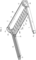
- the roller-blind apparatus described herein - designated as a whole in the figures by the reference number 10 - comprises a support 2, a winding roller 4 mounted on the support 2 so as to be rotatable about an axis of rotation I, and a covering sheet 6 that is mobile between a rolled-up configuration, where it is wound on the winding roller 4, and an extended configuration, where the covering sheet 6 extends from the winding roller 4 in an unwinding direction Y.
- the support 2 is designed to be fixed to any fixed structure, for example a wall, a frame, etc., at the opening or space that will be covered by the covering sheet 6.
- the unwinding direction Y will correspond to the longitudinal direction of the space or opening.
- the support 2 may present a wide range of configurations according to the requirements of the different applications.
- the support 2 comprises two opposed plates 2A, 2A', joined together by an end wall 2B that basically defines the overall width of the apparatus 10.
- the two plates 2A, 2A' are configured to receive between them the winding roller 4 and support it rotatably about the axis of rotation I.
- the apparatus 10 comprises a lid 8 removably mounted on the support 2 and shaped for closing the winding roller 4 inside an internal compartment C, leaving a slit 5, facing in the direction of unwinding Y, for passage of the covering sheet 6.
- the winding roller 4 has a generic tubular conformation, such that inside it a main axial cavity 4E is provided that extends from one end to the other of the roller 4.
- a rotary motor 12 is received in the end portion 4A of the winding roller 4, within the cavity 4E, and has a fixed part 12A, which is fixed to the plate 2A of the support 2.
- the mobile part 12B of the motor 12 is, instead, rendered fixed with respect to the winding roller 4, in particular via a coupling member 13 that engages, on the side of the end portion 4A, a set of axial cavities 4C, which are made within the thickness of the sleeve of the winding roller 4 and surround the main axial cavity 4E.
- a first pulley 15 is fixedly connected, in rotation, to the mobile part 12B of the motor 12 so as to be able to rotate together with the winding roller 4.
- a spring device 16 is received in the end portion 4B, opposite to the portion 4A, of the winding roller 4 and is fixed to the latter by way of a second coupling member 13' that itself also engages the aforesaid axial cavities 4C.
- a second pulley 17 is fixed to a rotatable part (not illustrated) of the spring device 16.
- the aforesaid rotatable part of the spring device 16 can be rotated with respect to the fixed part of the device itself that is fixed to the winding roller 4, against an elastic action exerted by the device itself.
- the spring device 16 may be of a known type, for example a gas spring, or else a spring device comprising an elastic member set between the fixed part and the mobile part referred to above.
- the apparatus 10 further comprises a slider 22, which is mobile in the unwinding direction Y, and to which an end edge of the covering sheet 4 is fixed.
- Two opposed lateral guides 7 receive the slider 22 according to a sliding coupling and guide it in its movement in the unwinding direction Y.
- the apparatus 10 comprises a first cable 24, which operatively connects the pulley 17 to the slider 22 and can be wound on/off the pulley 17 according to the direction of movement of the slider 22 in the direction Y.
- the apparatus 10 further comprises a second cable 26, which, instead, operatively connects the pulley 15 to the slider 22 and can itself also be wound on/off the pulley 15 according to the direction of movement of the slider 22 in the direction Y.
- Each of the two cables 24, 26 has a first end portion (not visible in the figures) fixed to the respective pulley 17, 15, and a second end portion 24B, 26B fixed to the slider 22 (as will be seen in greater detail in what follows).
- the cables 24 and 26 are enclosed within the slider 22 and the lateral guides 7 so as not to be visible from outside.
- the two cables 24 and 26 extend along one and the same ideal line.
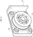
- Transmission pulleys 23 direct the cables 24 and 26 in the predefined path from the slider 22 to the respective pulleys 17, 15.
- the direction of winding of each of the two cables 24, 26 on the respective pulleys 15, 17 is opposite to the direction of winding of the covering sheet 6 on the winding roller 4 so that a movement of winding of the cables 24 and 26 on the respective pulleys 15 and 17 corresponds to a movement of unwinding of the covering sheet 6 off the winding roller 4, and vice versa.
- the two cables 24, 26 assume a configuration of maximum unwinding off the respective pulleys 15, 17, whereas, when the covering sheet 6 is in its extended configuration, the two cables 24, 26 assume a configuration of maximum winding on the respective pulleys 15, 17.
- the spring device 16 is configured for exerting, via its mobile part, a torque on the pulley 17 in a direction such that the cable 24 is pulled in a direction of winding on the pulley 17.
- the cable 24 pulls, through the slider 22, the covering sheet 6 in the unwinding direction Y.
- the covering sheet 4 is kept tensioned in a constant way, irrespective of its position in the unwinding direction Y and irrespective of the movement to which it is subjected, i.e., whether towards the rolled-up configuration or towards the extended configuration.
- the amount of the aforesaid elastic action exerted by the spring device 16 depends upon the level of preloading of the latter that is set during installation of the apparatus 10.
- the slider 22 comprises a regulating device 32 for regulating the length L of a useful portion 24C of the cable 24 that is provided for operatively connecting the pulley 17 to the slider 22.
- the above useful portion may be understood as the portion of the cable 24 that extends between the point of fixing of the cable to the pulley 17 and the point of entry of the cable into the regulating device 32.
- the regulating device 32 it is thus possible to regulate the level of preloading of the spring device 16 simply by intervening on the cable 24, within the slider 22.
- the regulating device 32 is located within the slider 22, and the latter has an outer casing 22A that can be removed to enable access to the regulating device 32.
- the regulating device 32 comprises a receiving roller 34 around which the end portion 24B of the cable 24 can be wound, according to a number of turns variable on the basis of the length L desired for the useful portion 24C of the cable 24.
- the length L may be varied in a controlled way by simply winding the end portion 24B of the cable 24 around the roller 34.
- the roller 34 is rotatable about an axis of rotation I1, and associated thereto is a unidirectional-motion mechanism configured to allow the roller 34 to rotate only in a direction of winding of the cable 24 useful for increasing the level of preloading of the spring device 16, i.e., in a direction of winding of the cable 24 on the roller 34 such as to enable pulling, instead, of the cable itself in a direction of unwinding off the pulley 17.
- the aforesaid unidirectional-motion mechanism may be constituted by a ratchet device.
- the receiving roller 34 is rotatably mounted on a base 36.
- This has a circular series of front teeth 36B configured for co-operating with a corresponding series of front teeth 34B, provided on the face of the roller 34 that faces the base 36.
- the teeth 34B or 36B of each series have, in the circumferential direction of the respective series, two opposite surfaces, of which a first surface S1 is orthogonal to the plane in which the series of teeth is made, and a second, opposite, surface S2 is, instead, inclined by an angle of less than 90° (considering the angle internal to the tooth).
- the surfaces S1 of the two series of the teeth 34B and 36B co-operate with one another to determine blocking of rotation of the roller 34 in a first direction, whereas the surfaces S2 of the same teeth co-operate with one another to enable, instead, the roller 34 to rotate in a second direction, opposite to the first direction.
- the roller 34 has a shaped central portion 34C, for example having a hexagonal shape, for engagement thereof by an appropriate tool, with the aid of which it is possible to rotate the roller 34 with respect to the base 36 in order to carry out regulation of the aforesaid length L.
- the regulating device 32 further comprises a blocking element for blocking any rotation of the roller 34 about its own axis I1, after the desired length L of the useful portion 24C of the cable 24 has been set.
- the end portion 24B is stably fixed to the regulating device 32, leaving the length L desired for the useful portion 24C.
- the above blocking element is constituted by a screw 38 provided for fastening the roller 34 to the base 36.
- the apparatus described herein may comprise a single cable, for example just the cable 24 of the embodiment illustrated or else a single cable deriving from joining of the two cables 24 and 26.
Landscapes
- Engineering & Computer Science (AREA)
- Architecture (AREA)
- Structural Engineering (AREA)
- Civil Engineering (AREA)
- Operating, Guiding And Securing Of Roll- Type Closing Members (AREA)
Applications Claiming Priority (1)
| Application Number | Priority Date | Filing Date | Title |
|---|---|---|---|
| IT202200022857 | 2022-11-07 |
Publications (1)
| Publication Number | Publication Date |
|---|---|
| EP4365401A1 true EP4365401A1 (fr) | 2024-05-08 |
Family
ID=85017999
Family Applications (1)
| Application Number | Title | Priority Date | Filing Date |
|---|---|---|---|
| EP23204258.0A Pending EP4365401A1 (fr) | 2022-11-07 | 2023-10-18 | Appareil de store à rouleau |
Country Status (1)
| Country | Link |
|---|---|
| EP (1) | EP4365401A1 (fr) |
Citations (4)
| Publication number | Priority date | Publication date | Assignee | Title |
|---|---|---|---|---|
| FR2604203A2 (fr) * | 1981-04-28 | 1988-03-25 | Franciaflex | Store a guidage lateral et a grande extension tel qu'un velum pour serres, verandas et analogues. |
| EP0289076A2 (fr) * | 1987-04-28 | 1988-11-02 | Winsol, Naamloze Vennotschap | Persienne |
| WO1996029498A1 (fr) * | 1995-03-22 | 1996-09-26 | Nicola Silvestri | Dispositif a ressort pour enrouler et derouler un tissu enroule sur d'un cylindre support |
| FR2957114A1 (fr) * | 2010-03-02 | 2011-09-09 | Aluroy | Volet d'occultation d'un ouvrant d'un batiment, et utilisation d'un tel volet |
-
2023
- 2023-10-18 EP EP23204258.0A patent/EP4365401A1/fr active Pending
Patent Citations (4)
| Publication number | Priority date | Publication date | Assignee | Title |
|---|---|---|---|---|
| FR2604203A2 (fr) * | 1981-04-28 | 1988-03-25 | Franciaflex | Store a guidage lateral et a grande extension tel qu'un velum pour serres, verandas et analogues. |
| EP0289076A2 (fr) * | 1987-04-28 | 1988-11-02 | Winsol, Naamloze Vennotschap | Persienne |
| WO1996029498A1 (fr) * | 1995-03-22 | 1996-09-26 | Nicola Silvestri | Dispositif a ressort pour enrouler et derouler un tissu enroule sur d'un cylindre support |
| FR2957114A1 (fr) * | 2010-03-02 | 2011-09-09 | Aluroy | Volet d'occultation d'un ouvrant d'un batiment, et utilisation d'un tel volet |
Similar Documents
| Publication | Publication Date | Title |
|---|---|---|
| US10273751B2 (en) | Methods and apparatus to control architectural opening covering assemblies | |
| US8739854B2 (en) | Pre-assembled and pre-tensioned shade with indexing gear tensioner | |
| US8113264B2 (en) | Tensioned roller shade system having a conical, grooved spool | |
| US20080314533A1 (en) | Device for Controlling Winding Speed of Winding Roll for Screen or Shade | |
| WO2003102344A1 (fr) | Dispositif de moustiquaire enroulable | |
| JP4558330B2 (ja) | 閉鎖又は日除け設備のための補償スプリングに張力を加える機構 | |
| CN118632971A (zh) | 可锁定的角部支架 | |
| JPH0978964A (ja) | 巻取式建物用網戸 | |
| JP7036402B2 (ja) | 開閉装置、シャッタ装置 | |
| CN103993819B (zh) | 一种卷帘及应用该卷帘制成的卷帘系统 | |
| CA2887718A1 (fr) | Fut comportant un element de fermeture a enrouler | |
| KR101988616B1 (ko) | 조절 실린더가 구비된 방충망 장치 | |
| CN224193259U (zh) | 电动窗帘 | |
| JPH11256959A (ja) | カーテン回転駆動装置 | |
| CN112005994B (zh) | 配备调节气缸的防虫网装置 | |
| JP7773921B2 (ja) | 操作装置 | |
| JP5438743B2 (ja) | 横型ブラインドのボトムレールの位置調整装置 | |
| JP2001251973A (ja) | 簡易ハウスのシート開閉装置 | |
| EP3412860B1 (fr) | Agencement de criblage avec moteur interne | |
| KR101946706B1 (ko) | 도어 닫힘 장치 | |
| JPH02523Y2 (fr) | ||
| KR20230023162A (ko) | 가감속 유닛이 구비된 롤방충망 | |
| JPS6123198Y2 (fr) | ||
| JP6408429B2 (ja) | コントロールケーブル装置 | |
| JP2006161414A (ja) | ロールブラインドの巻き強さ調整装置 |
Legal Events
| Date | Code | Title | Description |
|---|---|---|---|
| PUAI | Public reference made under article 153(3) epc to a published international application that has entered the european phase |
Free format text: ORIGINAL CODE: 0009012 |
|
| STAA | Information on the status of an ep patent application or granted ep patent |
Free format text: STATUS: THE APPLICATION HAS BEEN PUBLISHED |
|
| AK | Designated contracting states |
Kind code of ref document: A1 Designated state(s): AL AT BE BG CH CY CZ DE DK EE ES FI FR GB GR HR HU IE IS IT LI LT LU LV MC ME MK MT NL NO PL PT RO RS SE SI SK SM TR |
|
| STAA | Information on the status of an ep patent application or granted ep patent |
Free format text: STATUS: REQUEST FOR EXAMINATION WAS MADE |
|
| 17P | Request for examination filed |
Effective date: 20241031 |
|
| RBV | Designated contracting states (corrected) |
Designated state(s): AL AT BE BG CH CY CZ DE DK EE ES FI FR GB GR HR HU IE IS IT LI LT LU LV MC ME MK MT NL NO PL PT RO RS SE SI SK SM TR |