EP4365545A1 - Estimation non destructive de l'épaisseur de couche de revêtement sur la base d'une technique d'onde guidee photo-acoustique à fréquence de balayage - Google Patents
Estimation non destructive de l'épaisseur de couche de revêtement sur la base d'une technique d'onde guidee photo-acoustique à fréquence de balayage Download PDFInfo
- Publication number
- EP4365545A1 EP4365545A1 EP23204946.0A EP23204946A EP4365545A1 EP 4365545 A1 EP4365545 A1 EP 4365545A1 EP 23204946 A EP23204946 A EP 23204946A EP 4365545 A1 EP4365545 A1 EP 4365545A1
- Authority
- EP
- European Patent Office
- Prior art keywords
- frequency
- samples
- sut
- photoacoustic
- technique
- Prior art date
- Legal status (The legal status is an assumption and is not a legal conclusion. Google has not performed a legal analysis and makes no representation as to the accuracy of the status listed.)
- Granted
Links
Images


Classifications
-
- G—PHYSICS
- G01—MEASURING; TESTING
- G01B—MEASURING LENGTH, THICKNESS OR SIMILAR LINEAR DIMENSIONS; MEASURING ANGLES; MEASURING AREAS; MEASURING IRREGULARITIES OF SURFACES OR CONTOURS
- G01B11/00—Measuring arrangements characterised by the use of optical techniques
- G01B11/02—Measuring arrangements characterised by the use of optical techniques for measuring length, width or thickness
- G01B11/06—Measuring arrangements characterised by the use of optical techniques for measuring length, width or thickness for measuring thickness ; e.g. of sheet material
- G01B11/0616—Measuring arrangements characterised by the use of optical techniques for measuring length, width or thickness for measuring thickness ; e.g. of sheet material of coating
- G01B11/0666—Measuring arrangements characterised by the use of optical techniques for measuring length, width or thickness for measuring thickness ; e.g. of sheet material of coating using an exciting beam and a detection beam including surface acoustic waves [SAW]
-
- G—PHYSICS
- G01—MEASURING; TESTING
- G01B—MEASURING LENGTH, THICKNESS OR SIMILAR LINEAR DIMENSIONS; MEASURING ANGLES; MEASURING AREAS; MEASURING IRREGULARITIES OF SURFACES OR CONTOURS
- G01B11/00—Measuring arrangements characterised by the use of optical techniques
- G01B11/02—Measuring arrangements characterised by the use of optical techniques for measuring length, width or thickness
- G01B11/06—Measuring arrangements characterised by the use of optical techniques for measuring length, width or thickness for measuring thickness ; e.g. of sheet material
- G01B11/0616—Measuring arrangements characterised by the use of optical techniques for measuring length, width or thickness for measuring thickness ; e.g. of sheet material of coating
-
- G—PHYSICS
- G01—MEASURING; TESTING
- G01B—MEASURING LENGTH, THICKNESS OR SIMILAR LINEAR DIMENSIONS; MEASURING ANGLES; MEASURING AREAS; MEASURING IRREGULARITIES OF SURFACES OR CONTOURS
- G01B17/00—Measuring arrangements characterised by the use of infrasonic, sonic or ultrasonic vibrations
- G01B17/02—Measuring arrangements characterised by the use of infrasonic, sonic or ultrasonic vibrations for measuring thickness
- G01B17/025—Measuring arrangements characterised by the use of infrasonic, sonic or ultrasonic vibrations for measuring thickness for measuring thickness of coating
-
- G—PHYSICS
- G01—MEASURING; TESTING
- G01N—INVESTIGATING OR ANALYSING MATERIALS BY DETERMINING THEIR CHEMICAL OR PHYSICAL PROPERTIES
- G01N29/00—Investigating or analysing materials by the use of ultrasonic, sonic or infrasonic waves; Visualisation of the interior of objects by transmitting ultrasonic or sonic waves through the object
- G01N29/04—Analysing solids
- G01N29/12—Analysing solids by measuring frequency or resonance of acoustic waves
-
- G—PHYSICS
- G01—MEASURING; TESTING
- G01N—INVESTIGATING OR ANALYSING MATERIALS BY DETERMINING THEIR CHEMICAL OR PHYSICAL PROPERTIES
- G01N29/00—Investigating or analysing materials by the use of ultrasonic, sonic or infrasonic waves; Visualisation of the interior of objects by transmitting ultrasonic or sonic waves through the object
- G01N29/22—Details, e.g. general constructional or apparatus details
- G01N29/223—Supports, positioning or alignment in fixed situation
-
- G—PHYSICS
- G01—MEASURING; TESTING
- G01N—INVESTIGATING OR ANALYSING MATERIALS BY DETERMINING THEIR CHEMICAL OR PHYSICAL PROPERTIES
- G01N29/00—Investigating or analysing materials by the use of ultrasonic, sonic or infrasonic waves; Visualisation of the interior of objects by transmitting ultrasonic or sonic waves through the object
- G01N29/22—Details, e.g. general constructional or apparatus details
- G01N29/24—Probes
- G01N29/2418—Probes using optoacoustic interaction with the material, e.g. laser radiation, photoacoustics
-
- G—PHYSICS
- G01—MEASURING; TESTING
- G01N—INVESTIGATING OR ANALYSING MATERIALS BY DETERMINING THEIR CHEMICAL OR PHYSICAL PROPERTIES
- G01N29/00—Investigating or analysing materials by the use of ultrasonic, sonic or infrasonic waves; Visualisation of the interior of objects by transmitting ultrasonic or sonic waves through the object
- G01N29/44—Processing the detected response signal, e.g. electronic circuits specially adapted therefor
- G01N29/4409—Processing the detected response signal, e.g. electronic circuits specially adapted therefor by comparison
- G01N29/4436—Processing the detected response signal, e.g. electronic circuits specially adapted therefor by comparison with a reference signal
-
- G—PHYSICS
- G01—MEASURING; TESTING
- G01N—INVESTIGATING OR ANALYSING MATERIALS BY DETERMINING THEIR CHEMICAL OR PHYSICAL PROPERTIES
- G01N2291/00—Indexing codes associated with group G01N29/00
- G01N2291/02—Indexing codes associated with the analysed material
- G01N2291/023—Solids
- G01N2291/0231—Composite or layered materials
-
- G—PHYSICS
- G01—MEASURING; TESTING
- G01N—INVESTIGATING OR ANALYSING MATERIALS BY DETERMINING THEIR CHEMICAL OR PHYSICAL PROPERTIES
- G01N2291/00—Indexing codes associated with group G01N29/00
- G01N2291/02—Indexing codes associated with the analysed material
- G01N2291/028—Material parameters
- G01N2291/02854—Length, thickness
Definitions
- the disclosure herein generally relates to non-destructive estimation of coating layer thickness and, more particularly, to non-destructive estimation of coating layer thickness based on sweep frequency photo acoustic guided wave technique.
- Coating is the process of covering a surface or substrate with another substance to protect it temporarily or permanently from deterioration or degradation
- the coating of a substrate protects it from wear, corrosion, and also serves the cosmetic aspect, hence making coating technology an essential part industrial process. Since the coating impacts the overall performance of the substrate, the thickness of the coating is required to be optimum for the substrate. Further, uniformity of coating of paint is also necessary for establishing aesthetic value, in the absence of which problems such as blistering, blooming, and sagging can occur.
- non-destructive coating thickness determination are based on ultrasound and eddy current which involve contact measurement, making them unsuitable for large-scale industrial applications especially in online measurement.
- Other techniques for non-destructive coating thickness determination include beta backscatter measuring method, X-Ray fluorescence, THz time-domain spectroscopy and flash pulse phase thermography that require a prior knowledge of the refractive index of the surface under investigation, thus making them unsuitable for unknown samples.
- the use of sophisticated instrumentation, complicated procedure and harmful radiation set up a challenge for industrial deployment.
- a non-destructive coating thickness determination technique with a high precision determination of thickness that works for a variety of paint films and substrates and can be deployed easily in fast paced industrial environments.
- Embodiments of the present disclosure present technological improvements as solutions to one or more of the above-mentioned technical problems recognized by the inventors in conventional systems. For example, in one embodiment, a system for non-destructive estimation of coating layer thickness based on sweep frequency photo acoustic guided wave technique is provided.
- the system includes a memory storing instructions, one or more communication interfaces, and one or more hardware processors coupled to the memory via the one or more communication interfaces, wherein the one or more hardware processors are configured by the instructions to generate a plurality of photoacoustic guided waves from a plurality of samples, via one or more hardware processors, by irradiating the plurality of samples by an intensity modulated Continuous Wave (CW) laser diode at a pre-defined angle and a pre-defined sweep frequency, wherein the plurality of samples is associated with a known-thickness parameter.
- CW Continuous Wave
- the system is further configured to determine a frequency spectrum of the plurality of photoacoustic guided waves generated from the each of the plurality of samples, via the one or more hardware processors, based on a frequency spectra determination technique.
- the system is further configured to determine a resonance frequency from the frequency spectrum, via the one or more hardware processors, based on a sweep frequency photoacoustic guided wave technique.
- the system is further configured to plot a calibration curve based on the resonance frequency, via the one or more hardware processors, wherein the calibration curve associates the resonance frequency of each of the plurality of samples associated with the known-thickness parameter of each of the plurality of samples.
- a method for non-destructive estimation of coating layer thickness based on sweep frequency photo acoustic guided wave technique includes generating a plurality of photoacoustic guided waves from a plurality of samples by irradiating the plurality of samples by an intensity modulated Continuous Wave (CW) laser diode at a pre-defined angle and a pre-defined sweep frequency, wherein the plurality of samples is associated with a known-thickness parameter.
- the method is further configured for determining a frequency spectrum of the plurality of photoacoustic guided waves generated from the each of the plurality of samples based on a frequency spectra determination technique.
- the method is further configured for determining a resonance frequency from the frequency spectrum based on a sweep frequency photoacoustic guided wave technique.
- the method is further configured for plotting a calibration curve based on the resonance frequency wherein the calibration curve associates the resonance frequency of each of the plurality of samples associated with the known-thickness parameter of each of the plurality of samples.
- a non-transitory computer readable medium for non-destructive estimation of coating layer thickness based on sweep frequency photo acoustic guided wave technique.
- the method includes generating a plurality of photoacoustic guided waves from a plurality of samples by irradiating the plurality of samples by an intensity modulated Continuous Wave (CW) laser diode at a pre-defined angle and a pre-defined sweep frequency, wherein the plurality of samples is associated with a known-thickness parameter.
- the method is further configured for determining a frequency spectrum of the plurality of photoacoustic guided waves generated from the each of the plurality of samples based on a frequency spectra determination technique.
- CW Continuous Wave
- the method is further configured for determining a resonance frequency from the frequency spectrum based on a sweep frequency photoacoustic guided wave technique.
- the method is further configured for plotting a calibration curve based on the resonance frequency wherein the calibration curve associates the resonance frequency of each of the plurality of samples associated with the known-thickness parameter of each of the plurality of samples.
- FIG. 1 through FIG.7 where similar reference characters denote corresponding features consistently throughout the figures, there are shown preferred embodiments and these embodiments are described in the context of the following exemplary system and/or method.
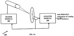
- FIG.1A is an exemplary block diagram of a system 100 for non-destructive estimation of coating layer thickness based on sweep frequency photo acoustic guided wave technique in accordance with some embodiments of the present disclosure.
- the system 100 includes a sensor module 102 and an analysis module 104.
- the sensor module 102 is configured to generate a plurality of photoacoustic guided waves from a plurality of samples.
- the sensor module 102 includes an intensity modulated continuous wave (CW) laser diode and an ultrasound sensor.
- the analysis module 104 comprises a processor(s), communication interface device(s), alternatively referred as input/output (I/O) interface(s), and one or more data storage devices or a memory operatively coupled to the processor(s).
- the processor in the processor module 104 is configured to (a) determine a frequency spectrum from the plurality of photoacoustic guided waves, (b) determine a resonance frequency from the frequency spectrum, (c) to plot a calibration curve and (d) estimate a coating layer thickness using the calibration curve.
- the plurality of photoacoustic guided waves is generated by irradiating the plurality of samples by the intensity modulated Continuous Wave (CW) laser diode at a pre-defined angle and a pre-defined sweep frequency, wherein the plurality of samples is associated with a known-thickness parameter.
- the intensity modulated continuous wave (CW) laser diode of wavelength 808 nm to irradiate the sample.
- the in-house developed Laser Driver Module (LDM) is used to modulate the intensity of the laser diode with the sweep frequency of 100 kHz to 300 kHz.
- the sample absorbs the laser radiation and produces acoustic waves which are acquired by the ultrasound sensor kept in contact with the sample via a coupling medium. Subsequently, the acoustic signal from the ultrasound sensor is recorded by a Vector Network Analyzer (VNA, Bode-100) and stored into the memory and processor for further analysis.
- VNA Vector Network Analyzer
- the analysis module 104 comprise a processor(s) (106), an Input/Output interface(s) (108), memory (110) and a database (112) as shown in FIG.1B .
- the processor (106) can be one or more hardware processors.
- the one or more hardware processors can be implemented as one or more microprocessors, microcomputers, microcontrollers, digital signal processors, central processing units, state machines, logic circuitries, and/or any devices that manipulate signals based on operational instructions.
- the one or more hardware processors is configured to fetch and execute computer-readable instructions stored in the memory.
- the system 100 can be implemented in a variety of computing systems including laptop computers, notebooks, hand-held devices such as mobile phones, workstations, mainframe computers, servers, a network cloud and the like.
- the Input/Output(I/O) interface(s) (108) can include a variety of software and hardware interfaces, for example, a web interface, a graphical user interface, a touch user interface (TUI) and the like and can facilitate multiple communications within a wide variety of networks N/W and protocol types, including wired networks, for example, LAN, cable, etc., and wireless networks, such as WLAN, cellular, or satellite.
- the I/O interface (s) can include one or more ports for connecting a number of devices (nodes) of the system 100 to one another or to another server.
- the memory (110) may include any computer-readable medium known in the art including, for example, volatile memory, such as static random-access memory (SRAM) and dynamic random-access memory (DRAM), and/or non-volatile memory, such as read only memory (ROM), erasable programmable ROM, flash memories, hard disks, optical disks, and magnetic tapes.
- volatile memory such as static random-access memory (SRAM) and dynamic random-access memory (DRAM)
- DRAM dynamic random-access memory
- non-volatile memory such as read only memory (ROM), erasable programmable ROM, flash memories, hard disks, optical disks, and magnetic tapes.
- the memory (110) may include a database (112) configured to include information regarding non-destructive estimation of coating layer thickness based on sweep frequency photo acoustic guided wave technique.
- the memory may comprise information pertaining to input(s)/output(s) of each step performed by the processor(s) of the system 100 and methods of the present disclosure.
- the database may be external (not shown) to the system 100 and coupled to the system via the I/O interface.
- the system 100 supports various connectivity options such as BLUETOOTH ® , USB, ZigBee and other cellular services.
- the network environment enables connection of various components of the system 100 using any communication link including Internet, WAN, MAN, and so on.
- the system 100 is implemented to operate as a stand-alone device.
- the system 100 may be implemented to work as a loosely coupled device to a smart computing environment. The components and functionalities of the system 100 are described further in detail.
- the various modules of the system 100 are configured for non-destructive estimation of coating layer thickness based on sweep frequency photo acoustic guided wave technique are implemented as at least one of a logically self-contained part of a software program, a self-contained hardware component, and/or, a self-contained hardware component with a logically self-contained part of a software program embedded into each of the hardware component that when executed perform the above method described herein.
- FIG.2 and FIG.3 are exemplary flow diagrams illustrating a method 200 and a method 300 for non-destructive estimation of coating layer thickness based on sweep frequency photo acoustic guided wave technique using the system 100 of FIG. 1A and FIG. 1B according to an embodiment of the present disclosure.
- a plurality of photoacoustic guided waves is generated from a plurality of samples at the sensor module 102.
- the plurality of photoacoustic guided waves is generated by irradiating the plurality of samples by the intensity modulated Continuous Wave (CW) laser diode at a pre-defined angle and a pre-defined sweep frequency.
- the plurality of samples is associated with a known-thickness parameter.
- the plurality of samples comprises of a metal including aluminum, steel, iron, etc., with varied thickness of coating layers.
- the intensity modulated Continuous Wave (CW) laser diode is a CW laser diode with associated intensity modulated at the pre-defined sweep frequency, wherein the pre-defined sweep frequency refers to excitation of the intensity modulated CW laser diode based on the plurality of samples.
- the pre-defined angle is incidence of the intensity modulated CW laser diode irradiation at an optimal angle of 45 degrees on the plurality of samples.
- the intensity modulated continuous wave (CW) laser diode of wavelength 808 nm is used to irradiate the sample.
- the in-house developed Laser Driver Module (LDM) is used to modulate the intensity of the laser diode with the pre-defined sweep frequency of 100 kHz to 300 kHz.
- the sample absorbs the laser radiation and produces acoustic waves which are acquired by the ultrasound sensor kept in contact with the sample via a coupling medium. Subsequently, the acoustic signal from the ultrasound sensor is recorded by a Vector Network Analyzer (VNA, Bode-100) and stored into the memory and processor for further analysis.
- VNA Vector Network Analyzer
- PA photoacoustic
- plural of photoacoustic guided waves and the “photoacoustic (PA) signal” can be used inter-changeably.
- guided photoacoustic waves are sensed from the sample to depict the thickness of the coating layer.
- the laser is excited obliquely at the pre-defined angle of 45° with respect to the sample's plane.
- a frequency spectrum is determined in the processor module 104 based on a frequency spectra determination technique.
- the frequency spectrum is determined for the plurality of photoacoustic guided waves generated from the each of the plurality of samples.
- the frequency spectra determination technique is chosen based on a heuristic technique close to the resonance frequency of the plurality of samples/SUT.
- the frequency spectra determination technique for obtaining the frequency spectra from the sample includes irradiating the sample with the intensity modulated laser diode at a narrow band of frequencies alternatively called as a "sweep frequency".
- the acoustic signals produced in the sample due to the laser irradiation exhibit identical frequencies as that of the laser diode excitation sweep frequency.
- the magnitude of the acoustic signal is maximum at a certain frequency which is approximately the resonance frequency of the sample.
- the sweep frequency acoustic signal is sensed by the ultrasound sensor and acquired by the Vector Network Analyzer (VNA, Bode-100). In VNA, the magnitude of acoustic signal is plotted at different frequencies, to obtain the required frequency spectra of the sample.
- VNA Vector Network Analyzer
- a resonance frequency is determined in the processor module 104 from the frequency spectrum, based on a sweep frequency photoacoustic guided wave technique.
- the sweep frequency photo acoustic guided wave technique uses a narrow band of frequencies such that a high frequency noise is reduced, and resonance frequency is acquired with a high signal to noise ratio (SNR).
- SNR signal to noise ratio
- the swept frequency intensity modulated CW laser diode is used to irradiate the sample.
- the sample absorbs the modulated laser radiation and undergoes thermoelastic expansion. While relaxing the sample releases a plurality of acoustic waves of same frequency as that of the excited frequencies. Further, the plurality of acoustic wave traverses show a maximum amplitude near the resonance frequency of the sample.
- a typical frequency resonance acoustic spectrum is received by the ultrasound sensor and acquired by the Vector Network Analyzer (VNA) for further processing.
- VNA Vector Network Analyzer
- the plurality of acoustic waves is generated due to the modulated laser irradiation these waves are called as photoacoustic waves and hence the terms “plurality of photoacoustic guided waves” and the “photoacoustic (PA) signal” are used inter-changeably in the disclosure.
- the laser is irradiated at a certain angle to produce guided waves and therefore, "plurality of photoacoustic guided waves” and the “photoacoustic (PA) signal” is also referred to as sweep frequency photoacoustic guided waves.
- a calibration curve is plotted based on the resonance frequency determined in the processor module 104.
- the calibration curve associates the resonance frequency of each of the plurality of samples against the known-thickness parameter of each of the plurality of samples.
- the calibration curve is utilized for non-destructive estimation of coating layer thickness of a sample under test (SUT) several steps as illustrated in the flowchart (300) of FIG.3 :
- a plurality of test photoacoustic guided waves is generated from the sample under test (SUT).
- the plurality of test photoacoustic guided waves is generated by irradiating the SUT by the intensity modulated Continuous Wave (CW) laser diode at the pre-defined angle and the pre-defined sweep frequency.
- CW Continuous Wave
- the intensity modulated Continuous Wave (CW) laser diode is a CW laser diode with an intensity modulated at the pre-defined sweep frequency, wherein the pre-defined sweep frequency refers to excitation of the intensity modulated CW laser diode based on the plurality of samples/SUT.
- the pre-defined angle is incidence of the intensity modulated CW laser diode irradiation at an optimal angle of 45 degrees on the plurality of samples/SUT.
- the intensity modulated continuous wave (CW) laser diode of wavelength 808 nm to irradiate the sample.
- the in-house developed Laser Driver Module is used to modulate the intensity of the laser diode with the pre-defined sweep frequency of 100 kHz to 300 kHz.
- the plurality of samples comprises of a metal including aluminum, steel, iron, etc., with varied thickness of coating layers.
- the sample under test is associated with a known-thickness parameter ranging between 100um to 2-3mm.
- a test frequency spectrum is determined based on the frequency spectrum determination technique.
- the plurality of test photoacoustic guided waves is generated from the each of the plurality of SUT.
- the frequency spectra determination technique is chosen based on a heuristic technique close to the resonance frequency of the plurality of samples/SUT.
- the frequency spectra determination technique is chosen based on a heuristic technique close to the resonance frequency of the plurality of samples/SUT.
- a test resonance frequency is determined from the test frequency spectrum based on the sweep frequency photoacoustic guided wave technique.
- the sweep frequency photo acoustic guided wave technique uses a narrow band of frequencies such that a high frequency noise can be reduced and resonance frequency is acquired with a high signal to noise ratio (SNR).
- SNR signal to noise ratio
- a test frequency spectrum is used for calibration curve preparation, there after the calibration curve with a known resonance frequency is utilized to determine coating thickness.
- a coating layer thickness is estimated for the SUT using the calibration curve and the test resonance frequency based on a mass-loading effect technique
- the thickness of coating layer is obtained by subtracting the thickness of the SUT from the overall thickness of the SUT with coating layer, wherein the SUT is a bare Al/metal sample.
- FIG. 4 shows that as the thickness of the sample increases the resonance peak shift leftwards or the resonance frequency reduces.
- FIG. 5 shows that the calibration curve between the resonance frequency and thickness exhibits the inverse relationship when the data points are plotted with the linear fitting.
- an arbitrary coating thickness (LR) is applied to the aluminum substrate. Experiment is performed to get the frequency spectra and thereby resonance frequency for this arbitrary coating thickness aluminum sample. This resonance frequency is used with the calibration curve to estimate the thickness of the arbitrary coating layer as shown in FIG.7 .
- the thickness estimated from the calibration curve is obtained as 458 ⁇ m which is close to the measured thickness (measured with the standard instrument) which is 460 ⁇ m.
- the thickness of coating layer is obtained by subtracting the thickness of the bare Al from the overall thickness of the Al with coating layer.
- This disclosure relates generally to non-destructive estimation of coating layer thickness based on sweep frequency photo acoustic guided wave technique. Coating of a substrate /surface protects it from wear, corrosion and also serves the cosmetic aspect, hence making coating technology is an essential part industrial process
- the existing techniques for coating thickness determination are either destructive or requires a prior knowledge of the refractive index of the surface under investigation or use of sophisticated instrumentation, complicated procedure and harmful radiation during industrial deployment.
- the disclosure utilizes an intensity modulated Continuous Wave (CW) laser diode to excite a sample thus, making the technique a partially contact based method. Further a calibration curve is plotted by determining a frequency spectrum and resonance frequency. The calibration curve is used for estimation of a coating layer thickness.
- CW Continuous Wave
- Such computer-readable storage means contain program-code means for implementation of one or more steps of the method, when the program runs on a server or mobile device or any suitable programmable device.
- the hardware device can be any kind of device which can be programmed including e.g., any kind of computer like a server or a personal computer, or the like, or any combination thereof.
- the device may also include means which could be e.g., hardware means like e.g., an application-specific integrated circuit (ASIC), a field-programmable gate array (FPGA), or a combination of hardware and software means, e.g., an ASIC and an FPGA, or at least one microprocessor and at least one memory with software processing components located therein.
- the means can include both hardware means and software means.
- the method embodiments described herein could be implemented in hardware and software.
- the device may also include software means. Alternatively, the embodiments may be implemented on different hardware devices, e.g., using a plurality of CPUs.
- the embodiments herein can comprise hardware and software elements.
- the embodiments that are implemented in software include but are not limited to, firmware, resident software, microcode, etc.
- the functions performed by various components described herein may be implemented in other components or combinations of other components.
- a computer-usable or computer readable medium can be any apparatus that can comprise, store, communicate, propagate, or transport the program for use by or in connection with the instruction execution system, apparatus, or device.
- a computer-readable storage medium refers to any type of physical memory on which information or data readable by a processor may be stored.
- a computer-readable storage medium may store instructions for execution by one or more processors, including instructions for causing the processor(s) to perform steps or stages consistent with the embodiments described herein.
- the term "computer-readable medium” should be understood to include tangible items and exclude carrier waves and transient signals, i.e., be non-transitory. Examples include random access memory (RAM), read-only memory (ROM), volatile memory, nonvolatile memory, hard drives, CD ROMs, DVDs, flash drives, disks, and any other known physical storage media.
Landscapes
- Physics & Mathematics (AREA)
- General Physics & Mathematics (AREA)
- Chemical & Material Sciences (AREA)
- Immunology (AREA)
- Health & Medical Sciences (AREA)
- Analytical Chemistry (AREA)
- Biochemistry (AREA)
- General Health & Medical Sciences (AREA)
- Pathology (AREA)
- Life Sciences & Earth Sciences (AREA)
- Acoustics & Sound (AREA)
- Engineering & Computer Science (AREA)
- Signal Processing (AREA)
- Optics & Photonics (AREA)
- Length Measuring Devices Characterised By Use Of Acoustic Means (AREA)
- Length Measuring Devices By Optical Means (AREA)
- Investigating Or Analyzing Materials By The Use Of Ultrasonic Waves (AREA)
Applications Claiming Priority (1)
| Application Number | Priority Date | Filing Date | Title |
|---|---|---|---|
| IN202221063431 | 2022-11-07 |
Publications (3)
| Publication Number | Publication Date |
|---|---|
| EP4365545A1 true EP4365545A1 (fr) | 2024-05-08 |
| EP4365545B1 EP4365545B1 (fr) | 2026-01-28 |
| EP4365545C0 EP4365545C0 (fr) | 2026-01-28 |
Family
ID=88506864
Family Applications (1)
| Application Number | Title | Priority Date | Filing Date |
|---|---|---|---|
| EP23204946.0A Active EP4365545B1 (fr) | 2022-11-07 | 2023-10-20 | Estimation non destructive de l'épaisseur de couche de revêtement sur la base d'une technique d'onde guidee photo-acoustique à fréquence de balayage |
Country Status (2)
| Country | Link |
|---|---|
| US (1) | US20240151515A1 (fr) |
| EP (1) | EP4365545B1 (fr) |
Citations (3)
| Publication number | Priority date | Publication date | Assignee | Title |
|---|---|---|---|---|
| CA2314305A1 (fr) * | 2000-07-21 | 2002-01-21 | National Research Council Of Canada | Appareil et methode de spectroscopie par ultrasons permettant de determiner l'epaisseur et d'autres proprietes de structures multicouches |
| US7798000B1 (en) * | 2005-10-28 | 2010-09-21 | Trustees Of Boston University | Non-destructive imaging, characterization or measurement of thin items using laser-generated lamb waves |
| WO2018020148A1 (fr) * | 2016-07-25 | 2018-02-01 | Centre Technique Des Industries Mecaniques | Procede et dispositif de mesure de l'epaisseur d'un revetement metallique |
Family Cites Families (7)
| Publication number | Priority date | Publication date | Assignee | Title |
|---|---|---|---|---|
| EP1679513A3 (fr) * | 1996-11-22 | 2007-01-10 | Perceptron, Inc. | Appareil de mesure de paramètres physiques et procédé correspondant |
| US6782337B2 (en) * | 2000-09-20 | 2004-08-24 | Kla-Tencor Technologies Corp. | Methods and systems for determining a critical dimension an a presence of defects on a specimen |
| US8102542B2 (en) * | 2005-09-30 | 2012-01-24 | National Research Council Of Canada | Method and apparatus for layer thickness measurement |
| DE102006054348B4 (de) * | 2006-06-02 | 2013-04-04 | Albert-Ludwigs-Universität Freiburg | Schichtdickensensor und Verfahren zur Überwachung von Abscheideprozessen |
| US20080291456A1 (en) * | 2007-05-24 | 2008-11-27 | Ghislain Lucien P | Sensor apparatus and method using optical interferometry |
| US8935960B2 (en) * | 2011-01-20 | 2015-01-20 | Massachusetts Institute Of Technology | Method and kit for stand-off detection of explosives |
| CN107830810B (zh) * | 2017-12-07 | 2019-11-01 | 南方电网科学研究院有限责任公司 | 一种涂层厚度的测量方法及测量系统 |
-
2023
- 2023-10-20 EP EP23204946.0A patent/EP4365545B1/fr active Active
- 2023-10-25 US US18/494,071 patent/US20240151515A1/en active Pending
Patent Citations (3)
| Publication number | Priority date | Publication date | Assignee | Title |
|---|---|---|---|---|
| CA2314305A1 (fr) * | 2000-07-21 | 2002-01-21 | National Research Council Of Canada | Appareil et methode de spectroscopie par ultrasons permettant de determiner l'epaisseur et d'autres proprietes de structures multicouches |
| US7798000B1 (en) * | 2005-10-28 | 2010-09-21 | Trustees Of Boston University | Non-destructive imaging, characterization or measurement of thin items using laser-generated lamb waves |
| WO2018020148A1 (fr) * | 2016-07-25 | 2018-02-01 | Centre Technique Des Industries Mecaniques | Procede et dispositif de mesure de l'epaisseur d'un revetement metallique |
Also Published As
| Publication number | Publication date |
|---|---|
| EP4365545B1 (fr) | 2026-01-28 |
| US20240151515A1 (en) | 2024-05-09 |
| EP4365545C0 (fr) | 2026-01-28 |
Similar Documents
| Publication | Publication Date | Title |
|---|---|---|
| Mulaveesala et al. | Pulse compression approach to infrared nondestructive characterization | |
| Chia et al. | Guided ultrasonic waves propagation imaging: a review | |
| Rogers et al. | Optical system for rapid materials characterization with the transient grating technique: Application to nondestructive evaluation of thin films used in microelectronics | |
| Huan et al. | A variable-frequency structural health monitoring system based on omnidirectional shear horizontal wave piezoelectric transducers | |
| JP6037340B2 (ja) | 表面の化学的性質の非接触測定装置および方法 | |
| US11039089B2 (en) | Thermal imaging for identifying a defect in a material | |
| US11656199B2 (en) | System and method for obtaining and analyzing flux leakage data in the inspection of oil and gas wells | |
| EP4036568B1 (fr) | Procédé et système permettant de déterminer des informations de viscosité de fluides | |
| CN116223435B (zh) | 基于太赫兹时域光谱获取材料物理参数的方法及测试系统 | |
| WO2016132452A1 (fr) | Dispositif de mesure d'ondes térahertz, procédé de mesure d'ondes térahertz, et programme informatique | |
| Hu et al. | High-resolution range profile reconstruction method for terahertz FMCW radar | |
| EP4365545B1 (fr) | Estimation non destructive de l'épaisseur de couche de revêtement sur la base d'une technique d'onde guidee photo-acoustique à fréquence de balayage | |
| Kiviniemi et al. | Time-resolved coherent anti-Stokes Raman-scattering measurements of I2 in solid Kr: Vibrational dephasing on the ground electronic state at 2.6–32 K | |
| Li et al. | Nondestructive detection of laser-cladding coating interface defects: a deep learning-enhanced laser ultrasonics approach | |
| Junjuri et al. | Review of Coherent Anti‐Stokes Raman Scattering Nonresonant Background Removal and Phase Retrieval Approaches: From Experimental Methods to Deep Learning Algorithms | |
| US6587794B1 (en) | Method for measuring thin metal films | |
| US9778229B2 (en) | Apparatus and method for measuring nonlinearity parameter using laser | |
| Suzuki et al. | Air-coupled ultrasonic vertical reflection method using pulse compression and various window functions: Feasibility study | |
| Hamada et al. | Visualization of slit defect by scanning nonlinear airborne ultrasound source technique using compressed sensing | |
| Balageas | Defense and illustration of time-resolved pulsed thermography for NDE | |
| Zhang et al. | Quantitative and nondestructive determination of residual stress for SiO2 thin film by laser-generated surface acoustic wave technique | |
| Murav’eva et al. | Analysis of reflected signals in testing cylindrical specimens by the multiple reflection echo-shadow method | |
| Jia et al. | Combining laser-excited edge resonance and ZGV resonance for measuring wave velocities and global thickness distribution of isotropic homogeneous plates | |
| Xu et al. | Complete characterization of molecular vibration using frequency resolved gating | |
| Zhang et al. | Noncontact evaluation of full elastic constants of perovskite MAPbBr3 via Photoacoustic eigen-spectrum analysis in one test |
Legal Events
| Date | Code | Title | Description |
|---|---|---|---|
| PUAI | Public reference made under article 153(3) epc to a published international application that has entered the european phase |
Free format text: ORIGINAL CODE: 0009012 |
|
| STAA | Information on the status of an ep patent application or granted ep patent |
Free format text: STATUS: THE APPLICATION HAS BEEN PUBLISHED |
|
| AK | Designated contracting states |
Kind code of ref document: A1 Designated state(s): AL AT BE BG CH CY CZ DE DK EE ES FI FR GB GR HR HU IE IS IT LI LT LU LV MC ME MK MT NL NO PL PT RO RS SE SI SK SM TR |
|
| STAA | Information on the status of an ep patent application or granted ep patent |
Free format text: STATUS: REQUEST FOR EXAMINATION WAS MADE |
|
| 17P | Request for examination filed |
Effective date: 20240723 |
|
| RBV | Designated contracting states (corrected) |
Designated state(s): AL AT BE BG CH CY CZ DE DK EE ES FI FR GB GR HR HU IE IS IT LI LT LU LV MC ME MK MT NL NO PL PT RO RS SE SI SK SM TR |
|
| GRAP | Despatch of communication of intention to grant a patent |
Free format text: ORIGINAL CODE: EPIDOSNIGR1 |
|
| STAA | Information on the status of an ep patent application or granted ep patent |
Free format text: STATUS: GRANT OF PATENT IS INTENDED |
|
| INTG | Intention to grant announced |
Effective date: 20251028 |
|
| GRAS | Grant fee paid |
Free format text: ORIGINAL CODE: EPIDOSNIGR3 |
|
| GRAA | (expected) grant |
Free format text: ORIGINAL CODE: 0009210 |
|
| STAA | Information on the status of an ep patent application or granted ep patent |
Free format text: STATUS: THE PATENT HAS BEEN GRANTED |
|
| AK | Designated contracting states |
Kind code of ref document: B1 Designated state(s): AL AT BE BG CH CY CZ DE DK EE ES FI FR GB GR HR HU IE IS IT LI LT LU LV MC ME MK MT NL NO PL PT RO RS SE SI SK SM TR |
|
| REG | Reference to a national code |
Ref country code: CH Ref legal event code: F10 Free format text: ST27 STATUS EVENT CODE: U-0-0-F10-F00 (AS PROVIDED BY THE NATIONAL OFFICE) Effective date: 20260128 Ref country code: GB Ref legal event code: FG4D |
|
| REG | Reference to a national code |
Ref country code: CH Ref legal event code: R17 Free format text: ST27 STATUS EVENT CODE: U-0-0-R10-R17 (AS PROVIDED BY THE NATIONAL OFFICE) Effective date: 20260212 |
|
| REG | Reference to a national code |
Ref country code: IE Ref legal event code: FG4D |
|
| U01 | Request for unitary effect filed |
Effective date: 20260128 |
|
| U07 | Unitary effect registered |
Designated state(s): AT BE BG DE DK EE FI FR IT LT LU LV MT NL PT RO SE SI Effective date: 20260203 |