EP4365603A1 - Dispositif mems ayant des performances de détection améliorées - Google Patents
Dispositif mems ayant des performances de détection améliorées Download PDFInfo
- Publication number
- EP4365603A1 EP4365603A1 EP23204864.5A EP23204864A EP4365603A1 EP 4365603 A1 EP4365603 A1 EP 4365603A1 EP 23204864 A EP23204864 A EP 23204864A EP 4365603 A1 EP4365603 A1 EP 4365603A1
- Authority
- EP
- European Patent Office
- Prior art keywords
- mass
- mems device
- substrate
- control structure
- operating state
- Prior art date
- Legal status (The legal status is an assumption and is not a legal conclusion. Google has not performed a legal analysis and makes no representation as to the accuracy of the status listed.)
- Pending
Links
- 238000001514 detection method Methods 0.000 title claims description 65
- 239000000758 substrate Substances 0.000 claims abstract description 51
- 238000004873 anchoring Methods 0.000 claims abstract description 35
- 238000000034 method Methods 0.000 claims description 6
- 230000001133 acceleration Effects 0.000 description 29
- 230000008878 coupling Effects 0.000 description 27
- 238000010168 coupling process Methods 0.000 description 27
- 238000005859 coupling reaction Methods 0.000 description 27
- 238000006073 displacement reaction Methods 0.000 description 9
- 230000035945 sensitivity Effects 0.000 description 6
- 239000003990 capacitor Substances 0.000 description 5
- 239000000463 material Substances 0.000 description 3
- 239000004065 semiconductor Substances 0.000 description 3
- 229910052710 silicon Inorganic materials 0.000 description 3
- 239000010703 silicon Substances 0.000 description 3
- 238000013461 design Methods 0.000 description 2
- 238000004519 manufacturing process Methods 0.000 description 2
- 229910021420 polycrystalline silicon Inorganic materials 0.000 description 2
- 229920005591 polysilicon Polymers 0.000 description 2
- 238000013459 approach Methods 0.000 description 1
- 210000000988 bone and bone Anatomy 0.000 description 1
- 230000005484 gravity Effects 0.000 description 1
- 230000010354 integration Effects 0.000 description 1
- 238000005259 measurement Methods 0.000 description 1
- 238000005459 micromachining Methods 0.000 description 1
- 238000012986 modification Methods 0.000 description 1
- 230000004048 modification Effects 0.000 description 1
- 238000012544 monitoring process Methods 0.000 description 1
- 150000003071 polychlorinated biphenyls Chemical class 0.000 description 1
- 230000035939 shock Effects 0.000 description 1
Images


Classifications
-
- G—PHYSICS
- G01—MEASURING; TESTING
- G01P—MEASURING LINEAR OR ANGULAR SPEED, ACCELERATION, DECELERATION, OR SHOCK; INDICATING PRESENCE, ABSENCE, OR DIRECTION, OF MOVEMENT
- G01P15/00—Measuring acceleration; Measuring deceleration; Measuring shock, i.e. sudden change of acceleration
- G01P15/02—Measuring acceleration; Measuring deceleration; Measuring shock, i.e. sudden change of acceleration by making use of inertia forces using solid seismic masses
- G01P15/08—Measuring acceleration; Measuring deceleration; Measuring shock, i.e. sudden change of acceleration by making use of inertia forces using solid seismic masses with conversion into electric or magnetic values
- G01P15/125—Measuring acceleration; Measuring deceleration; Measuring shock, i.e. sudden change of acceleration by making use of inertia forces using solid seismic masses with conversion into electric or magnetic values by capacitive pick-up
-
- G—PHYSICS
- G01—MEASURING; TESTING
- G01P—MEASURING LINEAR OR ANGULAR SPEED, ACCELERATION, DECELERATION, OR SHOCK; INDICATING PRESENCE, ABSENCE, OR DIRECTION, OF MOVEMENT
- G01P15/00—Measuring acceleration; Measuring deceleration; Measuring shock, i.e. sudden change of acceleration
- G01P15/02—Measuring acceleration; Measuring deceleration; Measuring shock, i.e. sudden change of acceleration by making use of inertia forces using solid seismic masses
- G01P15/08—Measuring acceleration; Measuring deceleration; Measuring shock, i.e. sudden change of acceleration by making use of inertia forces using solid seismic masses with conversion into electric or magnetic values
- G01P2015/0805—Measuring acceleration; Measuring deceleration; Measuring shock, i.e. sudden change of acceleration by making use of inertia forces using solid seismic masses with conversion into electric or magnetic values being provided with a particular type of spring-mass-system for defining the displacement of a seismic mass due to an external acceleration
- G01P2015/0808—Measuring acceleration; Measuring deceleration; Measuring shock, i.e. sudden change of acceleration by making use of inertia forces using solid seismic masses with conversion into electric or magnetic values being provided with a particular type of spring-mass-system for defining the displacement of a seismic mass due to an external acceleration for defining in-plane movement of the mass, i.e. movement of the mass in the plane of the substrate
- G01P2015/0811—Measuring acceleration; Measuring deceleration; Measuring shock, i.e. sudden change of acceleration by making use of inertia forces using solid seismic masses with conversion into electric or magnetic values being provided with a particular type of spring-mass-system for defining the displacement of a seismic mass due to an external acceleration for defining in-plane movement of the mass, i.e. movement of the mass in the plane of the substrate for one single degree of freedom of movement of the mass
- G01P2015/0814—Measuring acceleration; Measuring deceleration; Measuring shock, i.e. sudden change of acceleration by making use of inertia forces using solid seismic masses with conversion into electric or magnetic values being provided with a particular type of spring-mass-system for defining the displacement of a seismic mass due to an external acceleration for defining in-plane movement of the mass, i.e. movement of the mass in the plane of the substrate for one single degree of freedom of movement of the mass for translational movement of the mass, e.g. shuttle type
-
- G—PHYSICS
- G01—MEASURING; TESTING
- G01P—MEASURING LINEAR OR ANGULAR SPEED, ACCELERATION, DECELERATION, OR SHOCK; INDICATING PRESENCE, ABSENCE, OR DIRECTION, OF MOVEMENT
- G01P15/00—Measuring acceleration; Measuring deceleration; Measuring shock, i.e. sudden change of acceleration
- G01P15/02—Measuring acceleration; Measuring deceleration; Measuring shock, i.e. sudden change of acceleration by making use of inertia forces using solid seismic masses
- G01P15/08—Measuring acceleration; Measuring deceleration; Measuring shock, i.e. sudden change of acceleration by making use of inertia forces using solid seismic masses with conversion into electric or magnetic values
- G01P2015/0805—Measuring acceleration; Measuring deceleration; Measuring shock, i.e. sudden change of acceleration by making use of inertia forces using solid seismic masses with conversion into electric or magnetic values being provided with a particular type of spring-mass-system for defining the displacement of a seismic mass due to an external acceleration
- G01P2015/0857—Measuring acceleration; Measuring deceleration; Measuring shock, i.e. sudden change of acceleration by making use of inertia forces using solid seismic masses with conversion into electric or magnetic values being provided with a particular type of spring-mass-system for defining the displacement of a seismic mass due to an external acceleration using a particular shape of the suspension spring
-
- G—PHYSICS
- G01—MEASURING; TESTING
- G01P—MEASURING LINEAR OR ANGULAR SPEED, ACCELERATION, DECELERATION, OR SHOCK; INDICATING PRESENCE, ABSENCE, OR DIRECTION, OF MOVEMENT
- G01P15/00—Measuring acceleration; Measuring deceleration; Measuring shock, i.e. sudden change of acceleration
- G01P15/02—Measuring acceleration; Measuring deceleration; Measuring shock, i.e. sudden change of acceleration by making use of inertia forces using solid seismic masses
- G01P15/08—Measuring acceleration; Measuring deceleration; Measuring shock, i.e. sudden change of acceleration by making use of inertia forces using solid seismic masses with conversion into electric or magnetic values
- G01P2015/0862—Measuring acceleration; Measuring deceleration; Measuring shock, i.e. sudden change of acceleration by making use of inertia forces using solid seismic masses with conversion into electric or magnetic values being provided with particular means being integrated into a MEMS accelerometer structure for providing particular additional functionalities to those of a spring mass system
- G01P2015/0871—Measuring acceleration; Measuring deceleration; Measuring shock, i.e. sudden change of acceleration by making use of inertia forces using solid seismic masses with conversion into electric or magnetic values being provided with particular means being integrated into a MEMS accelerometer structure for providing particular additional functionalities to those of a spring mass system using stopper structures for limiting the travel of the seismic mass
-
- G—PHYSICS
- G01—MEASURING; TESTING
- G01P—MEASURING LINEAR OR ANGULAR SPEED, ACCELERATION, DECELERATION, OR SHOCK; INDICATING PRESENCE, ABSENCE, OR DIRECTION, OF MOVEMENT
- G01P15/00—Measuring acceleration; Measuring deceleration; Measuring shock, i.e. sudden change of acceleration
- G01P15/02—Measuring acceleration; Measuring deceleration; Measuring shock, i.e. sudden change of acceleration by making use of inertia forces using solid seismic masses
- G01P15/08—Measuring acceleration; Measuring deceleration; Measuring shock, i.e. sudden change of acceleration by making use of inertia forces using solid seismic masses with conversion into electric or magnetic values
- G01P2015/0862—Measuring acceleration; Measuring deceleration; Measuring shock, i.e. sudden change of acceleration by making use of inertia forces using solid seismic masses with conversion into electric or magnetic values being provided with particular means being integrated into a MEMS accelerometer structure for providing particular additional functionalities to those of a spring mass system
- G01P2015/0882—Measuring acceleration; Measuring deceleration; Measuring shock, i.e. sudden change of acceleration by making use of inertia forces using solid seismic masses with conversion into electric or magnetic values being provided with particular means being integrated into a MEMS accelerometer structure for providing particular additional functionalities to those of a spring mass system for providing damping of vibrations
Definitions
- the present invention relates to a MEMS device, in particular an inertial sensor, having improved detection performances.
- inertial sensors such as accelerometers and gyroscopes, of the MEMS (“Micro Electro-Mechanical Systems”) type are widely spread owing to the small dimensions and high detection sensitivity.
- MEMS Micro Electro-Mechanical Systems
- the MEMS inertial sensors are integrated into a wide range of electronic apparatuses, such as wearable devices, smartphones, laptops, etc.
- inertial sensors include shock monitoring, for example to detect car accidents or possible falls to the ground of a person; the detection of gestures by a user, such as a rotation of the screen of a smartphone or a specific type of user touch; and use as bone conductivity detectors, for example as a microphone in True Wireless Stereo (TWS) headphones.
- shock monitoring for example to detect car accidents or possible falls to the ground of a person
- gestures by a user such as a rotation of the screen of a smartphone or a specific type of user touch
- bone conductivity detectors for example as a microphone in True Wireless Stereo (TWS) headphones.
- TWS True Wireless Stereo
- low-G accelerometers are currently known for detecting low accelerations, for example having a Full Scale Range (FSR) equal to 16 g or 32 g, and high-G sensors for detecting high accelerations, for example having a full scale range equal to 128 g.
- FSR Full Scale Range
- two movable detection structures separate from each other are integrated in a same MEMS device, so as to detect both low accelerations and high accelerations.
- the simultaneous presence in the same MEMS device of two different movable detection structures entails disadvantages such as a greater number of necessary pads and a greater complexity in the required control circuitry (for example, dedicated ASICs, PCBs or CPUs, etc.), and more generally a greater integration area, a lower portability of the electronic device and a higher manufacturing cost.
- disadvantages such as a greater number of necessary pads and a greater complexity in the required control circuitry (for example, dedicated ASICs, PCBs or CPUs, etc.), and more generally a greater integration area, a lower portability of the electronic device and a higher manufacturing cost.
- the aim of the present invention is to overcome the disadvantages of the prior art.
- a MEMS device and a method for controlling the MEMS device are therefore provided, as defined in the attached claims.
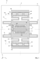
- Figure 1 shows a MEMS device 20, in particular a uniaxial MEMS accelerometer, in a Cartesian reference system XYZ comprising a first axis X, a second axis Y and a third axis Z.
- the MEMS device 20 is formed by micromachining techniques from a body of semiconductor material, for example silicon.
- the MEMS device 20 has a first and a second axis of symmetry A, B parallel to the first and, respectively, the second axis X, Y.
- the MEMS device 20 comprises a substrate 21, a movable structure 22 suspended on the substrate 21, and one or more elastic support elements, here four elastic support elements 23, which mechanically couple the movable structure 22 to the substrate 21.
- the movable structure 22 and the elastic support elements 23 are formed starting from layers of semiconductor material, for example silicon or polysilicon, and form substantially planar structures having main extension in an XY plane.
- the elastic support elements 23 and the movable structure 22 extend at a distance from the substrate 21 along the third axis Z.
- the elastic support elements 23 are folded flexures and are configured to allow a movement of the movable structure 22 according to one or more degrees of freedom, here along a detection direction parallel to the second axis Y.
- the elastic support elements 23 each extend between a respective anchoring region 25, fixed to the substrate 21, and the movable structure 22.
- the movable structure 22 comprises a detection mass 28, a first and a second control mass 29A, 29B, and first and second elastic coupling elements 30A, 30B which mechanically couple the first control mass 29A and, respectively, the second control mass 29B, to the detection mass 28.
- the first and the second elastic coupling elements 30A, 30B are folded flexures configured to deform along one or more directions, here parallel to the second axis Y.
- the first and the second elastic coupling elements 30A, 30B may have, along the detection direction, an equal or different elastic constant, here different and in particular greater, with respect to that of the elastic support elements 23.
- the first control mass 29A extends on a first side of the detection mass 28 and the second detection mass 29B extends on a second side of the detection mass 28 opposite to the first side with respect to the first axis of symmetry A.
- the first elastic coupling elements 30A extend, parallel to the second axis Y, between the first control mass 29A and the detection mass 28.
- the second elastic coupling elements 30B extend, parallel to the second axis Y, between the second control mass 29B and the detection mass 28.
- the MEMS device 20 further comprises first and second control electrodes 33A, 33B, fixed to the substrate 21 and capacitively coupled to the first and, respectively, the second control mass 29A, 29B.
- the first and the second control electrodes 33A, 33B are formed from semiconductor material, for example silicon or polysilicon.
- the first and the second control electrodes 33A, 33B are configured to cause a displacement of the first and, respectively, the second control mass 29A, 29B, along the detection direction.
- three first through-cavities 35A extend through the first control mass 29A, throughout the thickness of the first control mass 29A along the third axis Z
- three second through-cavities 35B extend through the second control mass 29B, throughout the thickness of the second control mass 29B along the third axis Z.
- the first and the second control masses 29A, 29B have, for each of the respective through-cavities 35A, 35B, a first and a second inner wall 36, 37, as shown in detail in the enlarged view of Figure 1A for the first through-cavities 35A.
- the first inner wall 36 is arranged, parallel to the second axis Y, at a smaller distance from the detection mass 28 with respect to the second inner wall 37.
- the first inner walls 36 are arranged towards the center of the movable structure 22, and the second inner walls 37 are arranged towards the outside of the movable structure 22.
- the first and the second inner walls 36, 37 extend parallel to the first axis X, on two sides of the first through-cavities 35A opposite to each other along the second axis Y.
- the first control electrodes 33A are each arranged inside a respective first through-cavity 35A.
- the second control electrodes 33B are each arranged inside a respective second through-cavity 35B.
- the first control electrodes 33A extend, parallel to the second axis Y, at a distance d 1 from the first inner wall 36 and at a distance d 2 from the second inner wall 37.
- the distance d 1 for example comprised between 1.8 ⁇ m and 5 ⁇ m, is smaller than the distance d 2 .
- the distance d 1 may be greater than a stroke value of the MEMS device 20, i.e. greater than the maximum displacement that the movable structure 22 may undergo, in use, parallel to the second axis Y.
- the distance d 2 may be equal to the distance d 1 plus a factor that may be chosen as a function of the stroke value of the MEMS device 20, according to the specific application.
- the MEMS device 20 further comprises a first and a second stopper 40A, 40B, fixed to the substrate 21 and extending at a distance from the first and, respectively, from the second control mass 29A, 29B parallel to the second axis Y.
- the first stopper 40A has a wall 42 facing an outer wall 43 of the first control mass 29A.
- the outer wall 43 of the first control mass 29A extends, parallel to the second axis Y, at a distance d 3 from the wall 42 of the first stopper 40A.
- the distance d 3 between the first control mass 29A and the first stopper 40A may be the same as or different, in particular here it is smaller, with respect to the distance d 1 between the first inner wall 36 of the first through-cavities 35A and the respective first control electrode 33A.
- the distance d 3 may be greater than or equal to the stroke value of the MEMS device 20. In this embodiment, the distance d 3 is equal to the stroke value of the MEMS device 20 and thus defines the stroke value thereof.
- first stopper 40A and the first control electrodes 33A also applies to the second stopper 40B and the second control electrodes 33B.
- the MEMS device 20 also comprises first and second voltage application means 45A, 45B, represented only schematically in Figure 1 , comprising a first and, respectively, a second conductive track 46A, 46B which extend on the substrate 21 and are represented, for the sake of simplicity, by dashed lines in Figure 1 .
- first and the second voltage application means 45A, 45B may further comprise contact pads and bond wires and are configured to provide a control voltage to the first and, respectively, the second control electrodes 33A, 33B.
- the MEMS device 20 further comprises a detection structure 50 of the capacitive type and configured to detect a movement of the detection mass 28 along the detection direction.
- the detection structure 50 comprises a first and a second detection capacitor 51A, 51B of the comb-finger type.
- the first and the second detection capacitors 51A, 51B each comprise a plurality of stator electrodes 53A, 53B fixed to the substrate 21 and a plurality of rotor electrodes 54A, 54B integral with the detection mass 28.
- the stator electrodes 53A, 53B are interdigitated with respective rotor electrodes 54A, 54B.
- a cavity 60 extends, parallel to the third axis Z, through the detection mass 28, throughout the thickness of the detection mass 28.
- the detection mass 28 has a frame shape.
- the stator electrodes 53A, 53B are arranged inside the cavity 60 and the rotor electrodes 54A, 54B are formed by protrusions of the detection mass 28 which extend towards the inside of the cavity 60.
- the MEMS device 20 is configured to detect an acceleration of the same MEMS device 20 along the detection direction, here parallel to the second axis Y.
- the MEMS device 20 may be controlled in a sensitive operating state, or low-acceleration operating state, which may be used to detect low-acceleration values, for example up to 16 g or 32 g, and in a high-band operating state, or high-acceleration operating state, which may be used to detect high-acceleration values, for example up to 128 g, where g represents the earth's gravity acceleration value equal to about 9.81 m/s 2 .
- the MEMS device 20 In the sensitive operating state, a zero voltage is applied to the first and the second control electrodes 33A, 33B. Therefore, in the sensitive operating state, the MEMS device 20 has, at equilibrium or at rest (for zero acceleration values), the configuration shown in Figure 1 .
- an inertial force parallel to the detection direction is applied on the movable structure 22.
- the inertial force causes a displacement of the movable structure 22 with respect to the equilibrium position.
- an elastic return force acts on the movable structure 22.
- the elastic return force has opposite direction with respect to the inertial force.
- the elastic return force is applied to the movable structure 22 by the elastic support elements 23.
- the modulus of the elastic return force is therefore a function of an elastic constant k 1 of the elastic support elements 23.
- the movable structure 22 moves along the detection direction as a single body.
- the movable structure 22 has an overall mass equal to M+2m, where M is the mass of the detection mass 28 and m the mass value of the first and the second control masses 29A, 29B. Consequently, the MEMS device 20 has, in the sensitive operating state, a resonance frequency f 1 given by f 1 ⁇ k 1 / M + 2 m .
- Figure 2 shows the MEMS device 20 at equilibrium or at rest (for zero acceleration values), in the high-band operating state.
- a voltage V p is applied to the first and the second control electrodes 33A, 33B through the first and the second voltage application means 45A, 45B.
- the voltage V p is greater than or equal to a pull-in voltage between the first control electrodes 33A and the respective first inner walls 36 of the first movable mass 29A.
- the first control mass 29A and the first control electrodes 33A are, in the high-band operating state, in a pull-in condition.
- the voltage V p generates an attractive electrostatic force between the first inner walls 36 of the first movable mass 29A and the first control electrodes 33A (arrow F c1 of Figure 2 ). Since the first control electrodes 33A are fixed to the substrate 21, the voltage V p causes a displacement of the first control mass 29A towards the first control electrodes 33A.
- the first inner wall 36 of the first through-cavities 35A is at a smaller distance d' 1 than the distance d 1 shown in Figure 1A relatively to the first operating state.
- the voltage V p also causes the second movable mass 29B, in particular the respective first inner walls 36, to move towards the second control electrodes 33B (electrostatic force indicated by the arrow F c2 of Figure 2 ).
- the electrostatic forces F c1 and F c2 are equal in modulus and have opposite directions; therefore, at equilibrium, in the absence of external accelerations, the elastic support elements 23 remain undeformed and the detection mass 28 does not undergo a displacement with respect to the rest position.
- the first elastic coupling elements 30A exert an elastic return force on the first control mass 29A (upwards in Figure 2 ). However, since the voltage V p is equal to or greater than the pull-in voltage, the elastic return force on the first control mass 29A is lower than the electrostatic attraction force F c1 applied by the first control electrodes 33A on the first control mass 29A.
- a resulting force directed towards the first and, respectively, the second stopper 40A, 40B acts on the first and the second control masses 29A, 29B.
- the resulting force maintains the first and the second control masses 29A, 29B in contact with the first and, respectively, the second stopper 40A, 40B.
- the first and the second control masses 29A, 29B form further anchoring elements to the substrate 21 of the detection mass 28.
- the voltage V p is such as to maintain the first control mass 29A and the first control electrodes 33A in the pull-in condition, and the second control mass 29B and the second control electrodes 33AB in the pull-in condition, even when the MEMS device 20 undergoes an acceleration along the detection direction.
- the first and the second control masses 29A, 29B remain fixed (anchored) to the first and the second stoppers 40A, 40B and the detection mass 28 moves with respect to the first and the second control masses 29A, 29B.
- the MEMS device 20 may be configured to operate in the presence of an acceleration, along the detection direction, lower than or equal to a maximum expected acceleration value (for example determinable during the design step according to the specific application).
- a maximum expected acceleration value for example determinable during the design step according to the specific application.
- the voltage V p may therefore be chosen in such a way that the corresponding pull-in force exerted by the first control electrodes 33A on the first control mass 29A is greater than the sum of the elastic return force exerted by the first elastic coupling elements 30A on the first control mass 29A in response to the maximum displacement of the detection mass 28, and of the apparent force experienced by the first control mass 29A in response to the maximum expected acceleration value of the MEMS device 20.
- the detection mass 28 undergoes an elastic return force which is a function not only of the elastic constant k 1 of the elastic support elements 23, but also of the elastic constant k 2 of the first and the second elastic coupling elements 30A, 30B.
- the first and the second elastic coupling elements 30A, 30B are mechanically arranged in parallel with the elastic support elements 23, between the detection mass 28 and the substrate 21.
- the MEMS device 20, in particular the detection mass 28, has an equivalent elastic constant k eq which is a function of the sum of the elastic constants k 1 , k 2 .
- the mass of the first and the second elastic coupling elements 30A, 30B, the movable structure 22 has an overall mass equal to M, i.e. corresponding to the sole detection mass 28.
- the MEMS device 20 has, in the high-band operating state, a resonance frequency f 2 given by f 2 ⁇ k 1 + k 2 / M .
- the value of the resonance frequencies f 1 , f 2 of the MEMS device 20 may be adjusted, and therefore the detection properties of the MEMS device 20 in the first and the second operating states.
- the resonance frequency f 2 is greater than the resonance frequency f 1 .
- the MEMS device 20 has higher detection sensitivity with respect to the high-band operating state.
- the MEMS device 20 has a greater full scale with respect to the sensitive operating state.
- the MEMS device 20 may be used to detect both low acceleration values and high acceleration values.
- FIG 3 shows a different embodiment of the present MEMS device, indicated here by 120.
- the MEMS device 120 has a general structure similar to that of the MEMS device 20 of Figure 1 ; consequently, elements in common are indicated by the same reference numerals and are not further described.
- the MEMS device 120 comprises the substrate 21, a movable structure 122, and elastic support elements, in particular first and second elastic support elements 123A, 123B, which mechanically couple the movable structure 122 to the substrate 21.
- the movable structure 122 comprises the detection mass 28, the first and the second control masses 29A, 29B, and the first and the second elastic coupling elements 30A, 30B.
- the first and the second elastic support elements 123A, 123B are coupled to the first and, respectively, the second control mass 29A, 29B.
- first elastic support elements 123A each extend between a respective anchoring region 25A and the first control mass 29A
- second elastic support elements 123B each extend between a respective anchoring region 25B and the second control mass 29B.
- the first and the second elastic support elements 123A, 123B are mechanically arranged in series with the first and, respectively, the second elastic coupling elements 30A, 30B, between the detection mass 28 and the substrate 21.
- the MEMS device 120 further comprises also the first and the second control electrodes 33A, 33B, the first and the second stoppers 40A, 40B and the detection structure 50.
- the MEMS device 120 also comprises voltage application means, not shown here, which allow a voltage to be applied to the first and the second control electrodes 33A, 33B, as discussed with reference to Figure 1 .
- the MEMS device 120 has a sensitive operating state, configured to detect low acceleration values, and a high-band operating state, configured to detect high acceleration values.
- a lower voltage than the pull-in voltage in particular a zero voltage, is applied between the first and the second control electrodes 33A, 33B and the first and the second control masses 29A, 29B.
- the movable structure 122 has, also here, an overall mass equal to M+2m. Consequently, the MEMS device 120 has, in the sensitive operating state, a resonance frequency f 1 given by f 1 ⁇ k eq / M + 2 m .
- the voltage V p is applied between the first control electrodes 33A and the first control mass 29A and between the second control electrodes 33B and the second control mass 29B, similarly to what has been discussed with reference to Figure 2 .
- first and the second control masses 29A, 29B remain in contact with the first and, respectively, with the second stopper 40A, 40B; and the detection mass 28 moves with respect to the equilibrium position.
- first and the second masses 29A, 29B are electrostatically fixed (anchored) to the first and, respectively, to the second stopper 40A, 40B.
- the equivalent elastic constant k eq of the MEMS device 120 is equal to the elastic constant k 2 of the first and second elastic coupling elements 30A, 30B.
- the MEMS device 120 has, in the high-band operating state, a resonance frequency f 2 given by f 2 ⁇ k 2 / M .
- the MEMS device 120 may also have both a high sensitivity and a high full scale.
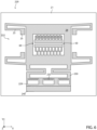
- FIG. 5 shows a further embodiment of the present MEMS device, indicated here by 220.
- the MEMS device 220 has a general structure similar to that of the MEMS device 20 of Figure 1 ; consequently, elements in common are indicated by the same reference numerals and are not further described.
- the MEMS device 220 comprises the substrate 21, a movable structure 222 and the elastic support elements 23.
- the movable structure 222 is formed by the detection mass 28, a control mass 229 and one or more elastic coupling elements, here two elastic coupling elements 230.
- control mass 229 and the elastic coupling elements 230 are respectively equal to the first control mass 29A and the first elastic coupling elements 30A of the MEMS device 20.
- the MEMS device 220 further comprises a plurality of control electrodes 233 and a stopper 240, which are respectively equal to the first control electrodes 33A and the first stopper 40A of the MEMS device 20 of Figure 1 .
- the MEMS device 220 does not have the second control mass, the second elastic coupling elements, the second stopper and the second control electrodes.
- the MEMS device 220 is not symmetrical parallel to the first X axis.
- the operation of the MEMS device 220 is similar to the operation of the MEMS devices 20, 120 of Figures 1 and 3 and will therefore not be further described in detail.
- Figure 6 shows the MEMS device 220 in the high-band operating state, where the control electrodes 233 and the control mass 229 are in a pull-in condition.
- the equivalent elastic constant of the MEMS device 220 is a function of the elastic constant of the elastic support elements 23.
- the equivalent elastic constant of the MEMS device 220 is a function of the elastic constant of both the elastic support elements 23 and the elastic coupling elements 230.
- the MEMS device 220 has a high detection versatility and may detect both high and low acceleration values.
- the MEMS device 220 has a low die area occupation and may therefore have a low manufacturing cost.
- the elastic support elements, the anchoring regions, the stoppers, the elastic coupling elements, the through-cavities of the control masses, etc. may be different in number and shape from what has been described and illustrated herein.
- the elastic support elements and the elastic coupling elements may be flexures of different type, for example linear flexures.
- the detection structure 50 may comprise a different number of detection capacitors and/or the detection capacitors may be of different type, for example parallelplate capacitors.
- the MEMS device may be based on a detection principle other than the capacitive one.
- the detection structure 50 may be configured to detect a movement of the detection mass 28 according to a piezoelectric or piezoresistive detection principle.
- control electrodes may be used to control the MEMS device in a number of operating states greater than two.
- a voltage other than zero and lower than the pull-in voltage may be applied to the control electrodes, which allows the elastic constant of the elastic support elements and/or of the elastic coupling elements to be modified due to the known phenomenon of the electrostatic softening.
- voltages that are different from each other may be applied to the first and the second control electrodes, according to the specific application.
- the pull-in voltage may only be applied to the first control electrodes or to the second control electrodes.
- the present MEMS device may be a biaxial or triaxial accelerometer.
- the movable structure may be configured to move along one or more directions.
- the MEMS device may comprise multiple movable structures, suitably configured to each detect an acceleration along a respective axis.
- the MEMS device may be an inertial sensor other than an accelerometer, for example a gyroscope, or a MEMS sensor of a different type, configured to detect a physical quantity on the basis of a movement of a movable structure.
- an accelerometer for example a gyroscope
- MEMS sensor of a different type configured to detect a physical quantity on the basis of a movement of a movable structure.
Landscapes
- Physics & Mathematics (AREA)
- General Physics & Mathematics (AREA)
- Micromachines (AREA)
- Pressure Sensors (AREA)
Applications Claiming Priority (1)
| Application Number | Priority Date | Filing Date | Title |
|---|---|---|---|
| IT102022000022782A IT202200022782A1 (it) | 2022-11-04 | 2022-11-04 | Dispositivo mems avente prestazioni di rilevamento migliorate |
Publications (1)
| Publication Number | Publication Date |
|---|---|
| EP4365603A1 true EP4365603A1 (fr) | 2024-05-08 |
Family
ID=84829571
Family Applications (1)
| Application Number | Title | Priority Date | Filing Date |
|---|---|---|---|
| EP23204864.5A Pending EP4365603A1 (fr) | 2022-11-04 | 2023-10-20 | Dispositif mems ayant des performances de détection améliorées |
Country Status (3)
| Country | Link |
|---|---|
| US (1) | US20240151741A1 (fr) |
| EP (1) | EP4365603A1 (fr) |
| IT (1) | IT202200022782A1 (fr) |
Citations (2)
| Publication number | Priority date | Publication date | Assignee | Title |
|---|---|---|---|---|
| US5914553A (en) * | 1997-06-16 | 1999-06-22 | Cornell Research Foundation, Inc. | Multistable tunable micromechanical resonators |
| US20200400712A1 (en) * | 2019-06-20 | 2020-12-24 | Stmicroelectronics S.R.L. | Mems inertial sensor with high resistance to stiction |
Family Cites Families (1)
| Publication number | Priority date | Publication date | Assignee | Title |
|---|---|---|---|---|
| US9300227B2 (en) * | 2013-06-05 | 2016-03-29 | Silicon Laboratories Inc. | Monolithic body MEMS devices |
-
2022
- 2022-11-04 IT IT102022000022782A patent/IT202200022782A1/it unknown
-
2023
- 2023-10-20 EP EP23204864.5A patent/EP4365603A1/fr active Pending
- 2023-10-27 US US18/496,653 patent/US20240151741A1/en active Pending
Patent Citations (2)
| Publication number | Priority date | Publication date | Assignee | Title |
|---|---|---|---|---|
| US5914553A (en) * | 1997-06-16 | 1999-06-22 | Cornell Research Foundation, Inc. | Multistable tunable micromechanical resonators |
| US20200400712A1 (en) * | 2019-06-20 | 2020-12-24 | Stmicroelectronics S.R.L. | Mems inertial sensor with high resistance to stiction |
Also Published As
| Publication number | Publication date |
|---|---|
| US20240151741A1 (en) | 2024-05-09 |
| IT202200022782A1 (it) | 2024-05-04 |
Similar Documents
| Publication | Publication Date | Title |
|---|---|---|
| EP2462408B1 (fr) | Dispositifs capteur inertiel micro-usinés | |
| US8739626B2 (en) | Micromachined inertial sensor devices | |
| US6520017B1 (en) | Micromechanical spin angular acceleration sensor | |
| US10545167B2 (en) | Multiple-axis resonant accelerometers | |
| US7013730B2 (en) | Internally shock caged serpentine flexure for micro-machined accelerometer | |
| US8011247B2 (en) | Multistage proof-mass movement deceleration within MEMS structures | |
| CN107003333B9 (zh) | Mems 传感器和半导体封装 | |
| US20040112133A1 (en) | Methods and systems for decelerating proof mass movements within mems structures | |
| CN112114163B (zh) | 具有高耐粘滞性的mems惯性传感器 | |
| Mohammed et al. | An optimization technique for performance improvement of gap-changeable MEMS accelerometers | |
| EP3717868B1 (fr) | Capteur mems avec rejet de charge de dispositif d'ancrage décalé | |
| US10241129B1 (en) | MEMS piston-tube based capacitive accelerometer | |
| EP4365603A1 (fr) | Dispositif mems ayant des performances de détection améliorées | |
| Rödjegård et al. | A monolithic three-axis SOI-accelerometer with uniform sensitivity | |
| CN221764498U (zh) | Mems设备和电子设备 | |
| EP4582815A1 (fr) | Accéléromètre mems à haute robustesse mécanique | |
| JPH11295075A (ja) | 三次元角速度センサ | |
| Zhao et al. | Design of a Capacitive SOI Micromachined Accelerometer |
Legal Events
| Date | Code | Title | Description |
|---|---|---|---|
| PUAI | Public reference made under article 153(3) epc to a published international application that has entered the european phase |
Free format text: ORIGINAL CODE: 0009012 |
|
| STAA | Information on the status of an ep patent application or granted ep patent |
Free format text: STATUS: THE APPLICATION HAS BEEN PUBLISHED |
|
| AK | Designated contracting states |
Kind code of ref document: A1 Designated state(s): AL AT BE BG CH CY CZ DE DK EE ES FI FR GB GR HR HU IE IS IT LI LT LU LV MC ME MK MT NL NO PL PT RO RS SE SI SK SM TR |
|
| STAA | Information on the status of an ep patent application or granted ep patent |
Free format text: STATUS: REQUEST FOR EXAMINATION WAS MADE |
|
| 17P | Request for examination filed |
Effective date: 20241107 |
|
| RBV | Designated contracting states (corrected) |
Designated state(s): AL AT BE BG CH CY CZ DE DK EE ES FI FR GB GR HR HU IE IS IT LI LT LU LV MC ME MK MT NL NO PL PT RO RS SE SI SK SM TR |