EP4366016A1 - Batterie secondaire à électrolyte non aqueux - Google Patents
Batterie secondaire à électrolyte non aqueux Download PDFInfo
- Publication number
- EP4366016A1 EP4366016A1 EP22832739.1A EP22832739A EP4366016A1 EP 4366016 A1 EP4366016 A1 EP 4366016A1 EP 22832739 A EP22832739 A EP 22832739A EP 4366016 A1 EP4366016 A1 EP 4366016A1
- Authority
- EP
- European Patent Office
- Prior art keywords
- carbon particles
- half region
- secondary battery
- negative electrode
- aqueous electrolyte
- Prior art date
- Legal status (The legal status is an assumption and is not a legal conclusion. Google has not performed a legal analysis and makes no representation as to the accuracy of the status listed.)
- Pending
Links
Images

Classifications
-
- H—ELECTRICITY
- H01—ELECTRIC ELEMENTS
- H01M—PROCESSES OR MEANS, e.g. BATTERIES, FOR THE DIRECT CONVERSION OF CHEMICAL ENERGY INTO ELECTRICAL ENERGY
- H01M4/00—Electrodes
- H01M4/02—Electrodes composed of, or comprising, active material
- H01M4/13—Electrodes for accumulators with non-aqueous electrolyte, e.g. for lithium-accumulators; Processes of manufacture thereof
-
- H—ELECTRICITY
- H01—ELECTRIC ELEMENTS
- H01M—PROCESSES OR MEANS, e.g. BATTERIES, FOR THE DIRECT CONVERSION OF CHEMICAL ENERGY INTO ELECTRICAL ENERGY
- H01M4/00—Electrodes
- H01M4/02—Electrodes composed of, or comprising, active material
- H01M4/36—Selection of substances as active materials, active masses, active liquids
- H01M4/58—Selection of substances as active materials, active masses, active liquids of inorganic compounds other than oxides or hydroxides, e.g. sulfides, selenides, tellurides, halogenides or LiCoFy; of polyanionic structures, e.g. phosphates, silicates or borates
- H01M4/583—Carbonaceous material, e.g. graphite-intercalation compounds or CFx
- H01M4/587—Carbonaceous material, e.g. graphite-intercalation compounds or CFx for inserting or intercalating light metals
-
- H—ELECTRICITY
- H01—ELECTRIC ELEMENTS
- H01M—PROCESSES OR MEANS, e.g. BATTERIES, FOR THE DIRECT CONVERSION OF CHEMICAL ENERGY INTO ELECTRICAL ENERGY
- H01M10/00—Secondary cells; Manufacture thereof
- H01M10/05—Accumulators with non-aqueous electrolyte
- H01M10/052—Li-accumulators
-
- H—ELECTRICITY
- H01—ELECTRIC ELEMENTS
- H01M—PROCESSES OR MEANS, e.g. BATTERIES, FOR THE DIRECT CONVERSION OF CHEMICAL ENERGY INTO ELECTRICAL ENERGY
- H01M10/00—Secondary cells; Manufacture thereof
- H01M10/05—Accumulators with non-aqueous electrolyte
- H01M10/052—Li-accumulators
- H01M10/0525—Rocking-chair batteries, i.e. batteries with lithium insertion or intercalation in both electrodes; Lithium-ion batteries
-
- H—ELECTRICITY
- H01—ELECTRIC ELEMENTS
- H01M—PROCESSES OR MEANS, e.g. BATTERIES, FOR THE DIRECT CONVERSION OF CHEMICAL ENERGY INTO ELECTRICAL ENERGY
- H01M10/00—Secondary cells; Manufacture thereof
- H01M10/05—Accumulators with non-aqueous electrolyte
- H01M10/058—Construction or manufacture
- H01M10/0587—Construction or manufacture of accumulators having only wound construction elements, i.e. wound positive electrodes, wound negative electrodes and wound separators
-
- H—ELECTRICITY
- H01—ELECTRIC ELEMENTS
- H01M—PROCESSES OR MEANS, e.g. BATTERIES, FOR THE DIRECT CONVERSION OF CHEMICAL ENERGY INTO ELECTRICAL ENERGY
- H01M4/00—Electrodes
- H01M4/02—Electrodes composed of, or comprising, active material
- H01M4/13—Electrodes for accumulators with non-aqueous electrolyte, e.g. for lithium-accumulators; Processes of manufacture thereof
- H01M4/133—Electrodes based on carbonaceous material, e.g. graphite-intercalation compounds or CFx
-
- H—ELECTRICITY
- H01—ELECTRIC ELEMENTS
- H01M—PROCESSES OR MEANS, e.g. BATTERIES, FOR THE DIRECT CONVERSION OF CHEMICAL ENERGY INTO ELECTRICAL ENERGY
- H01M4/00—Electrodes
- H01M4/02—Electrodes composed of, or comprising, active material
- H01M4/36—Selection of substances as active materials, active masses, active liquids
-
- H—ELECTRICITY
- H01—ELECTRIC ELEMENTS
- H01M—PROCESSES OR MEANS, e.g. BATTERIES, FOR THE DIRECT CONVERSION OF CHEMICAL ENERGY INTO ELECTRICAL ENERGY
- H01M50/00—Constructional details or processes of manufacture of the non-active parts of electrochemical cells other than fuel cells, e.g. hybrid cells
- H01M50/10—Primary casings; Jackets or wrappings
- H01M50/102—Primary casings; Jackets or wrappings characterised by their shape or physical structure
- H01M50/107—Primary casings; Jackets or wrappings characterised by their shape or physical structure having curved cross-section, e.g. round or elliptic
-
- H—ELECTRICITY
- H01—ELECTRIC ELEMENTS
- H01M—PROCESSES OR MEANS, e.g. BATTERIES, FOR THE DIRECT CONVERSION OF CHEMICAL ENERGY INTO ELECTRICAL ENERGY
- H01M4/00—Electrodes
- H01M4/02—Electrodes composed of, or comprising, active material
- H01M2004/021—Physical characteristics, e.g. porosity, surface area
-
- H—ELECTRICITY
- H01—ELECTRIC ELEMENTS
- H01M—PROCESSES OR MEANS, e.g. BATTERIES, FOR THE DIRECT CONVERSION OF CHEMICAL ENERGY INTO ELECTRICAL ENERGY
- H01M2300/00—Electrolytes
- H01M2300/0017—Non-aqueous electrolytes
-
- Y—GENERAL TAGGING OF NEW TECHNOLOGICAL DEVELOPMENTS; GENERAL TAGGING OF CROSS-SECTIONAL TECHNOLOGIES SPANNING OVER SEVERAL SECTIONS OF THE IPC; TECHNICAL SUBJECTS COVERED BY FORMER USPC CROSS-REFERENCE ART COLLECTIONS [XRACs] AND DIGESTS
- Y02—TECHNOLOGIES OR APPLICATIONS FOR MITIGATION OR ADAPTATION AGAINST CLIMATE CHANGE
- Y02E—REDUCTION OF GREENHOUSE GAS [GHG] EMISSIONS, RELATED TO ENERGY GENERATION, TRANSMISSION OR DISTRIBUTION
- Y02E60/00—Enabling technologies; Technologies with a potential or indirect contribution to GHG emissions mitigation
- Y02E60/10—Energy storage using batteries
Definitions
- the present disclosure relates to a non-aqueous electrolyte secondary battery.
- a non-aqueous electrolyte secondary battery which includes a positive electrode, a negative electrode, and a non-aqueous electrolyte and performs charge and discharge by moving lithium ions and the like between the positive electrode and the negative electrode is widely used.
- Patent Literature 1 discloses a cylindrical battery in which a mixture layer on a positive electrode lead side (sealing assembly side) has a high interparticle porosity
- Patent Literature 2 discloses a cylindrical battery in which a mixture layer on a negative electrode lead side (can bottom side) has a high interparticle porosity
- Patent Literature 3 discloses a secondary battery in which an electrode density in both end region in a width direction of a negative electrode is higher than an electrode density in a central region in the width direction of the negative electrode
- Patent Literature 4 discloses a secondary battery in which an amount of pores per unit area of a positive electrode in a positive electrode mixture layer existing between adjacent positive electrode current collectors and negative electrode current collectors is larger in the central region than in the end region in a width direction of the positive electrode.
- An object of the present disclosure is to provide a non-aqueous electrolyte secondary battery capable of improving charge-discharge cycle characteristics.
- a non-aqueous electrolyte secondary battery is a non-aqueous electrolyte secondary battery including: an electrode assembly in which a positive electrode and a negative electrode face each other with a separator interposed therebetween; and a battery case accommodating the electrode assembly, in which the negative electrode has a negative electrode mixture layer containing first carbon particles and second carbon particles having an internal porosity smaller than that of the first carbon particles, when the non-aqueous electrolyte secondary battery is used in a fixed state, and the electrode assembly in the fixed state is equally divided into an upper half region and a lower half region with respect to a vertical direction, the second carbon particles are contained more in the upper half region than in the lower half region.
- a non-aqueous electrolyte secondary battery is a non-aqueous electrolyte secondary battery including: an electrode assembly in which a positive electrode and a negative electrode face each other with a separator interposed therebetween; an exterior can having a bottomed cylindrical shape for accommodating the electrode assembly; and a sealing assembly for closing an opening of the exterior can, in which the negative electrode has a negative electrode mixture layer containing first carbon particles and second carbon particles having an internal porosity smaller than that of the first carbon particles, and when the electrode assembly is equally divided into a half region on a sealing assembly side and a half region on a bottom portion side of the exterior can with respect to an insertion direction into the exterior can, the second carbon particles are contained more in the half region on the sealing assembly side than in the half region on the bottom portion side of the exterior can.
- a non-aqueous electrolyte secondary battery is a non-aqueous electrolyte secondary battery including: an electrode assembly in which a positive electrode and a negative electrode face each other with a separator interposed therebetween; an exterior can having a bottomed cylindrical shape for accommodating the electrode assembly; and a sealing assembly for closing an opening of the exterior can, in which the negative electrode has a negative electrode mixture layer containing first carbon particles and second carbon particles having an internal porosity smaller than that of the first carbon particles, and when the electrode assembly is equally divided into a half region on a sealing assembly side and a half region on a bottom portion side of the exterior can with respect to an insertion direction into the exterior can, the second carbon particles are contained more in the half region on the bottom portion side of the exterior can than in the half region on the sealing assembly side.
- charge-discharge cycle characteristics can be improved.
- a non-aqueous electrolyte secondary battery of the present disclosure is not limited to the embodiment described below.
- the drawings referred to in the description of the embodiment are schematically illustrated.
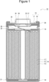
- FIG. 1 is a cross-sectional view of a non-aqueous electrolyte secondary battery as an example of the embodiment.
- a non-aqueous electrolyte secondary battery 10 illustrated in FIG. 1 includes a wound electrode assembly 14 formed by winding a positive electrode 11 and a negative electrode 12 with a separator 13 interposed therebetween, a non-aqueous electrolytic solution, insulating plates 18 and 19 respectively disposed above and below the electrode assembly 14, and a battery case 15 that accommodates the above-described members.
- the battery case 15 includes an exterior can 16 and a sealing assembly 17 that closes an opening of the exterior can 16.
- the wound electrode assembly 14 another form of electrode assembly such as a stacked electrode assembly formed by alternately stacking positive electrodes and negative electrodes with a separator interposed therebetween may be applied.
- the battery case 15 include a bottomed cylindrical exterior can having a cylindrical shape, a rectangular shape, a coin shape, a button shape, or the like, and a pouch exterior package formed by laminating a resin sheet and a metal sheet.
- the exterior can 16 is, for example, a bottomed cylindrical metal case.
- a gasket 28 is provided between the exterior can 16 and the sealing assembly 17 to ensure sealability of the inside of the battery.
- the exterior can 16 has, for example, a projecting portion 22 supporting the sealing assembly 17, and a part of a side face of the exterior can 16 projects inward to form the projecting portion 22.
- the projecting portion 22 is preferably formed in an annular shape along the circumferential direction of the exterior can 16, and supports the sealing assembly 17 on the upper face thereof.
- the sealing assembly 17 has a structure in which a filter 23, a lower vent member 24, an insulating member 25, an upper vent member 26, and a cap 27 are stacked in this order from the electrode assembly 14 side.
- Each member constituting the sealing assembly 17 has, for example, a disk shape or a ring shape, and each member except for the insulating member 25 is electrically connected to each other.
- the lower vent member 24 and the upper vent member 26 are connected to each other at the central portions of respective members, and the insulating member 25 is interposed between peripheral parts of respective members.
- the lower vent member 24 deforms so as to push up the upper vent member 26 toward the cap 27 and breaks, and a current path between the lower vent member 24 and the upper vent member 26 is cut off, for example.
- the upper vent member 26 breaks, and the gas is discharged from an opening of the cap 27.
- a positive electrode lead 20 attached to the positive electrode 11 extends to the sealing assembly 17 side through a through hole of the insulating plate 18, and a negative electrode lead 21 attached to the negative electrode 12 extends to the bottom portion side of the exterior can 16 through the outside of the insulating plate 19.
- the positive electrode lead 20 is connected to a lower face of the filter 23 which is a bottom plate of the sealing assembly 17 by welding or the like, and the cap 27 which is a top plate of the sealing assembly 17 electrically connected to the filter 23 serves as a positive electrode terminal.
- the negative electrode lead 21 is connected to the inner face of the bottom of the exterior can 16 by welding or the like, and the exterior can 16 serves as a negative electrode terminal.
- the sealing assembly 17 is the upper face of the battery case 15, the face of the exterior can 16 facing the sealing assembly 17 is the bottom face of the battery case 15, and the side face connecting the upper face and the bottom face is the side face of the battery case 15.
- a direction from the bottom face to the upper face of the battery case 15 is defined as a height direction of the non-aqueous electrolyte secondary battery 10.
- the positive electrode 11 includes a positive electrode current collector and a positive electrode mixture layer provided on the positive electrode current collector.
- a foil of a metal which is stable in the potential range of the positive electrode 11, such as aluminum, a film in which the metal is disposed on a surface layer thereof, or the like can be used for the positive electrode current collector.
- the positive electrode mixture layer contains a positive electrode active material, and optionally contains an additive such as a binder or a conductive agent.
- the positive electrode 11 is produced, for example, by applying a positive electrode mixture slurry containing a positive electrode active material, a binder, a conductive agent, and the like onto the positive electrode current collector, drying the slurry to form the positive electrode mixture layer, and then rolling the positive electrode mixture layer with a rolling roller or the like.
- Examples of the positive electrode active material include lithium-metal composite oxides containing transition metal elements such as Co, Mn, and Ni.
- Examples of the lithium-metal composite oxide include Li x CoO 2 , Li x NiO 2 , Li x MnO 2 , Li X Co y Ni 1-y O 2 , Li x Co y M 1-y O z , Li x Ni 1-y M y O z , Li x Mn 2 O 4 , Li x Mn 2-y M y O 4 , LiMPO 4 , and Li 2 MPO 4 F (M; at least one of Na, Mg, Sc, Y, Mn, Fe, Co, Ni, Cu, Zn, Al, Cr, Pb, Sb, and B, 0 ⁇ x ⁇ 1.2, 0 ⁇ y ⁇ 0.9, 2.0 ⁇ z ⁇ 2.3).
- the positive electrode active material preferably contains a lithium-nickel composite oxide such as Li x NiO 2 , Li x Co y Ni 1-y O 2 , or Li x Ni 1-y M y O z (M; at least one of Na, Mg, Sc, Y, Mn, Fe, Co, Ni, Cu, Zn, Al, Cr, Pb, Sb, and B, 0 ⁇ x ⁇ 1.2, 0 ⁇ y ⁇ 0.9, 2.0 ⁇ z ⁇ 2.3) from the viewpoint of achieving increase in the capacity of the non-aqueous electrolyte secondary battery.
- a lithium-nickel composite oxide such as Li x NiO 2 , Li x Co y Ni 1-y O 2 , or Li x Ni 1-y M y O z (M; at least one of Na, Mg, Sc, Y, Mn, Fe, Co, Ni, Cu, Zn, Al, Cr, Pb, Sb, and B, 0 ⁇ x ⁇ 1.2, 0
- fluorine-based resins such as polytetrafluoroethylene (PTFE) and polyvinylidene fluoride (PVDF), polyacrylonitrile (PAN), polyimide (PI), acrylic resins, polyolefin-based resins, styrene butadiene rubber (SBR), nitrile rubber
- NBR carboxymethyl cellulose
- PAA polyacrylic acid
- PVA polyvinyl alcohol
- the content of the binder in the positive electrode mixture layer is, for example, preferably 0.5 mass% to 10 mass%, and more preferably 1 mass% to 5 mass%.
- Examples of the conductive agent include carbon particles such as carbon black (CB), acetylene black (AB), Ketjenblack, carbon nanotube (CNT), and graphite. These may be independently used, or two or more thereof may be used in combination.
- the negative electrode 12 includes a negative electrode current collector and a negative electrode mixture layer provided on the negative electrode current collector.
- a foil of a metal which is stable within the potential range of the negative electrode, such as copper, a film in which the metal is disposed on a surface layer thereof, or the like is used for the negative electrode current collector.
- the negative electrode mixture layer contains a negative electrode active material, and optionally contains an additive such as a binder or a conductive agent.
- binder examples include fluorine-based resins such as polytetrafluoroethylene (PTFE) and polyvinylidene fluoride (PVDF), polyacrylonitrile (PAN), polyimide (PI), acrylic resins, polyolefin-based resins, styrene butadiene rubber (SBR), nitrile rubber (NBR), carboxymethyl cellulose (CMC) or a salt thereof, polyacrylic acid (PAA) or a salt thereof, polyvinyl alcohol (PVA), and the like. These may be independently used, or two or more thereof may be used in combination.
- the content of the binder in the negative electrode mixture layer is, for example, preferably 0.5 mass% to 10 mass%, and more preferably 1 mass% to 5 mass%.
- Examples of the conductive agent include carbon particles such as carbon black (CB), acetylene black (AB), Ketjenblack, carbon nanotube (CNT), and graphite. These may be independently used, or two or more thereof may be used in combination.
- the negative electrode active material contained in the negative electrode mixture layer contains a plurality of carbon particles having different internal porosities.
- FIG. 2 is a cross-sectional view illustrating an example of carbon particles used as a negative electrode active material.
- the carbon particle 30 in a cross-sectional view of the carbon particle 30, the carbon particle 30 has a closed void 34 (hereinafter, the internal void 34) that is not connected from the inside of the particle to the particle surface, and a void 36 (hereinafter, the external void 36) that is connected from the inside of the particle to the particle surface.
- the carbon particles 30 used as the negative electrode active material of the present embodiment include first carbon particles and second carbon particles having a lower internal porosity than the first carbon particles.
- the internal porosity of the carbon particle is a two-dimensional value obtained from a ratio of an area of the internal voids 34 of the carbon particle to the cross-sectional area of the carbon particle.
- the internal porosity of the carbon particles is determined by the following procedure.
- the internal porosity of the first carbon particles is, for example, preferably greater than or equal to 8% and less than or equal to 20%, more preferably greater than or equal to 10% and less than or equal to 18%, and still more preferably greater than or equal to 12% and less than or equal to 16% from the viewpoint of improving the charge-discharge cycle characteristics.
- the internal porosity of the second carbon particles only needs to be smaller than the internal porosity of the first carbon particles, but is preferably less than or equal to 5%, more preferably greater than or equal to 1% and less than or equal to 5%, and still more preferably greater than or equal to 3% and less than or equal to 5% from the viewpoint of improving the charge-discharge cycle characteristics.
- the first carbon particle and the second carbon particle are produced, for example, as follows.
- coke (precursor) as a main raw material is pulverized into a predetermined size, and the pulverized coke is aggregated with a binder, and then the coke is fired at a temperature of 2600°C or higher to be graphitized in a state of being further pressure-molded into a block shape.
- the block-shaped molded assembly after graphitization is pulverized and sieved to obtain carbon particles having a desired size.
- the internal porosity can be adjusted to 8% to 20% by the amount of a volatile component added to the block-shaped molded assembly.
- the binder can be used as the volatile component.
- pitch is exemplified.
- coke (precursor) as a main raw material is pulverized into a predetermined size, and fired at a temperature of 2600°C or higher to be graphitized in a state where the pulverized coke is aggregated with a binder, and then sieved to obtain carbon particles having a desired size.
- the internal porosity can be adjusted to 5% or less depending on the particle diameter of the precursor after pulverization, the particle diameter of the precursor in an aggregated state, and the like.
- the average particle diameter (median diameter D50) of the pulverized precursor is preferably in the range of 12 ⁇ m to 20 ⁇ m. When the internal porosity is reduced to 5% or less, it is preferable to increase the particle diameter of the precursor after pulverization.
- the first carbon particles and the second carbon particles used in the present embodiment are preferably graphite such as natural graphite and artificial graphite, but may be a carbon material other than graphite. In the case of graphite, artificial graphite is preferable from the viewpoint of ease of adjustment of the internal porosity and the like.
- the interplanar spacing (d 002 ) between (002) planes of the first carbon particle and the second carbon particle used in the present embodiment as measured by a wide angle X-ray diffraction method is, for example, preferably greater than or equal to 0.3354 nm, more preferably greater than or equal to 0.3357 nm, and preferably less than 0.340 nm, more preferably less than or equal to 0.338 nm.
- the crystallite sizes (Lc(002)) of the first carbon particle and the second carbon particle used in the present embodiment determined by an X-ray diffraction method are, for example, preferably greater than or equal to 5 nm, more preferably greater than or equal to 10 nm, and preferably less than or equal to 300 nm, more preferably less than or equal to 200 nm.
- the interplanar spacing (d 002 ) and the crystallite size (Lc(002)) satisfy the above ranges, the battery capacity of the non-aqueous electrolyte secondary battery tends to be larger than when the above ranges are not satisfied.
- the negative electrode active material may contain a material capable of reversibly occluding and releasing lithium ions, for example, a metal to be alloyed with lithium such as silicon (Si) or tin (Sn), an alloy containing a metal element such as Si or Sn, a composite oxide, or the like.
- a metal to be alloyed with lithium such as silicon (Si) or tin (Sn)
- an alloy containing a metal element such as Si or Sn
- a composite oxide or the like.
- FIG. 3 is a side view illustrating a state in which the non-aqueous electrolyte secondary battery illustrated in FIG. 1 is fixed.
- the non-aqueous electrolyte secondary battery of the present embodiment is desirably used as an installed type or stationary power source installed indoors or outdoors, or a power source installed in a movable object such as an electric vehicle.
- the non-aqueous electrolyte secondary battery 10 used as such a power source is installed and used in a fixed state on a fixing portion 38 such as a mounting table, a case, or the like.
- the phrase "used in a fixed state” means that the orientation of the non-aqueous electrolyte secondary battery 10 is not significantly changed after the non-aqueous electrolyte secondary battery 10 is installed in the fixing portion 38 and started to be used.
- a non-aqueous electrolyte secondary battery used as a power source of a mobile phone is not included in the case of being used in a fixed state because it is placed in any orientation with use of the mobile phone.
- an arrow Z indicates the vertical direction (gravity direction). That is, the non-aqueous electrolyte secondary battery 10 illustrated in FIG. 3 is provided to stand along the vertical direction. More specifically, the non-aqueous electrolyte secondary battery 10 illustrated in FIG. 3 is installed such that the bottom of the battery case 15 is in contact with the fixing portion 38, and the height direction of the non-aqueous electrolyte secondary battery 10 is along the vertical direction.
- FIG. 4 is a perspective view of a wound electrode assembly used in the non-aqueous electrolyte secondary battery of FIG. 3 .
- a region A of the electrode assembly 14 illustrated in FIG. 4 is a region corresponding to an upper half region 10a when the electrode assembly 14 accommodated in the non-aqueous electrolyte secondary battery 10 illustrated in FIG. 3 is divided into two equal parts in the vertical direction.
- a region B of the electrode assembly 14 illustrated in FIG. 4 is a region corresponding to a lower half region 10b when the electrode assembly 14 accommodated in the non-aqueous electrolyte secondary battery 10 illustrated in FIG. 3 is divided into two equal parts in the vertical direction.
- the second carbon particles contained in the negative electrode mixture layer are contained more in the region A (that is, the upper half region 10a illustrated in FIG. 3 ) shown in FIG. 4 than in the region B (that is, the lower half region 10billustrated in FIG. 3 ) shown in FIG. 4 . Since the height direction of the non-aqueous electrolyte secondary battery 10 illustrated in FIG. 3 is along the vertical direction, the vertical direction can be rephrased as the height direction of the non-aqueous electrolyte secondary battery 10.
- the second carbon particles contained in the negative electrode mixture layer are contained more in the upper half region than in the lower half region.
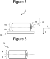
- FIG. 5 is a side view illustrating another example of a state in which the non-aqueous electrolyte secondary battery illustrated in FIG. 1 is fixed.
- an arrow Z indicates the vertical direction (gravity direction)
- an arrow Y indicates the direction (horizontal direction) orthogonal to the vertical direction.
- the non-aqueous electrolyte secondary battery 10 illustrated in FIG. 5 is installed such that the side face of the battery case 15 is in contact with the fixing portion 38, and the height direction of the non-aqueous electrolyte secondary battery 10 is along the direction (horizontal direction) orthogonal to the vertical direction.
- FIG. 6 is a perspective view of a wound electrode assembly used in the non-aqueous electrolyte secondary battery of FIG. 5 .
- a region A of the electrode assembly 14 illustrated in FIG. 6 is a region corresponding to an upper half region 10a when the electrode assembly 14 accommodated in the non-aqueous electrolyte secondary battery 10 illustrated in FIG. 5 is equally divided with respect to the vertical direction.
- a region B of the electrode assembly 14 illustrated in FIG. 6 is a region corresponding to a lower half region 10b when the electrode assembly 14 accommodated in the non-aqueous electrolyte secondary battery 10 illustrated in FIG. 5 is equally divided with respect to the vertical direction.
- the second carbon particles contained in the negative electrode mixture layer are contained more in the region A (that is, the upper half region 10a illustrated in FIG. 5 ) shown in FIG. 6 than in the region B (that is, the lower half region 10b illustrated in FIG. 5 ) shown in FIG. 6 .
- the non-aqueous electrolytic solution in the battery case 15 is unevenly distributed in the lower part in the vertical direction by gravity, and the non-aqueous electrolytic solution is easily depleted in the upper part in the vertical direction.
- charge-discharge cycle characteristics are deteriorated.
- carbon particles having a small internal porosity are hard and difficult to be crushed, a large number of relatively large voids are likely to be formed between carbon particles in the negative electrode mixture layer when the negative electrode 12 is manufactured.
- the non-aqueous electrolytic solution is retained in relatively large inter-particle voids formed in the negative electrode mixture layer in a large number in the upper half region 10a, so that retention of the non-aqueous electrolytic solution on the upper side in the vertical direction is improved.
- the non-aqueous electrolytic solution is suppressed from being unevenly distributed in the lower part in the vertical direction, and the charge-discharge cycle characteristics can be improved accordingly.
- a non-aqueous electrolyte secondary battery including a bottomed cylindrical battery case having a cylindrical shape and a wound electrode assembly has been described as an example.
- the same effect can be obtained even in the case of a non-aqueous electrolyte secondary battery including a bottomed cylindrical battery case having a rectangular shape, a stacked electrode assembly, or the like.
- the first carbon particles having a larger internal porosity than the second carbon particles are disposed more in the lower half region 10b than in the upper half region 10a. Since the carbon particles having a large internal porosity are soft and easily crushed, voids between the carbon particles in the negative electrode mixture layer are reduced when the negative electrode 12 is manufactured, and relatively large voids are reduced. Therefore, by disposing more first carbon particles having a larger internal porosity than the second carbon particles in the lower half region 10b than in the upper half region 10a, the non-aqueous electrolytic solution is less likely to be excessively retained in the negative electrode mixture layer in the lower half region 10b. As a result, the non-aqueous electrolytic solution is further suppressed from being unevenly distributed in the lower part in the vertical direction, and the charge-discharge cycle characteristics can be further improved accordingly.
- the second carbon particles may be contained more in the upper half region 10a than in the lower half region 10b, but for example, from the viewpoint of further improving the charge-discharge cycle characteristics, the ratio of the second carbon particles contained in the upper half region 10a to the second carbon particles contained in the lower half region 10b is preferably from 60:40 to 100:0 in mass ratio. In addition, from the viewpoint of further improving the charge-discharge cycle characteristics, the ratio of the first carbon particles and the second carbon particles in the upper half region 10a is preferably 70:30 to 0: 100 in mass ratio. In addition, from the viewpoint of further improving the charge-discharge cycle characteristics, the ratio of the first carbon particles and the second carbon particles in the lower half region 10b is preferably 80:20 to 100:0 in mass ratio.
- the non-aqueous electrolyte secondary battery 10 illustrated in FIG. 3 is fixed such that the bottom of the exterior can 16 is in contact with the fixing portion 38.
- the electrode assembly 14 is equally divided into a half region on the sealing assembly 17 side and a half region on the bottom portion side of the exterior can 16 with respect to the insertion direction into the exterior can 16
- the second carbon particles having an internal porosity smaller than that of the first carbon particles are contained more in the half region on the sealing assembly 17 side than in the half region on the bottom portion side of the exterior can 16.
- the first carbon particles having a larger internal porosity than the second carbon particles are preferably contained more in the half region on the bottom portion side of the exterior can 16 than in the half region of the sealing assembly 17 side.
- the non-aqueous electrolyte secondary battery 10 can be fixed such that the sealing assembly 17 is in contact with the fixing portion 38 instead of the bottom of the exterior can 16.
- the electrode assembly 14 is equally divided into the half region on the sealing assembly 17 side and the half region on the bottom portion side of the exterior can 16 with respect to the insertion direction into the exterior can 16, the second carbon particles having an internal porosity smaller than that of the first carbon particles are contained more in the half region on the bottom portion side of the exterior can 16 than in the half region on the sealing assembly 17 side.
- the first carbon particles having a larger internal porosity than the second carbon particles are preferably contained more in the half region of the sealing assembly 17 side than in the half region on the bottom portion side of the exterior can 16. This improves the charge-discharge cycle characteristics of the non-aqueous electrolyte secondary battery 10.
- the internal porosity, the content ratio, and the like of each carbon particle may be the same as described above.
- a negative electrode active material containing first carbon particles (second carbon particles as necessary) and a binder are mixed together with a solvent to prepare a slurry B for the lower half region 10b.
- the negative electrode active material containing the second carbon particles (the first carbon particles as necessary) and the binder are mixed together with a solvent to prepare a slurry A for the upper half region 10a.
- the slurries A and B are applied so as to be along the longitudinal direction of the negative electrode current collector, and be adjacent to each other in the width direction orthogonal to the longitudinal direction.
- the slurries A and B are alternately applied in a predetermined length along the longitudinal direction of the negative electrode current collector.
- the applied slurry is then dried, and the coated film (negative electrode mixture layer) is rolled to form a negative electrode according to the present embodiment.
- the second carbon particles can be disposed more in the half region on the sealing assembly side than in the half region on the bottom portion side of the exterior can, or can be disposed more in the half region on the bottom side portion of the exterior can than in the half region on the sealing assembly side.
- a porous sheet having ion permeability and insulation properties is used as the separator 13, for example.
- the porous sheet include a fine porous thin film, a woven fabric, and a nonwoven fabric.
- olefin-based resin such as polyethylene or polypropylene, cellulose, or the like is suitable.
- the separator 13 may be a stack having a cellulose fiber layer and a fiber layer of thermoplastic resin such as olefin-based resin.
- the separator 13 may be a multilayer separator having a polyethylene layer and a polypropylene layer, and a separator having a surface coated with a material such as aramid-based resin or ceramic may be used.
- the non-aqueous electrolytic solution contains a non-aqueous solvent and an electrolyte salt dissolved in the non-aqueous solvent.
- the non-aqueous solvent examples include esters, ethers, nitriles such as acetonitrile, amides such as dimethylformamide, and mixed solvents of two or more types thereof.
- the non-aqueous solvent may contain a halogen-substituted product in which at least a part of hydrogen in these solvents is substituted with a halogen atom such as fluorine.
- esters examples include cyclic carbonic acid esters such as ethylene carbonate (EC), propylene carbonate (PC), and butylene carbonate; chain carbonic acid esters such as dimethyl carbonate (DMC), ethyl methyl carbonate (EMC), diethyl carbonate (DEC), methyl propyl carbonate, ethyl propyl carbonate, and methyl isopropyl carbonate; cyclic carboxylic acid esters such as ⁇ -butyrolactone and ⁇ -valerolactone; and chain carboxylic acid esters such as methyl acetate, ethyl acetate, propyl acetate, methyl propionate (MP), and ethyl propionate.
- cyclic carbonic acid esters such as ethylene carbonate (EC), propylene carbonate (PC), and butylene carbonate
- chain carbonic acid esters such as dimethyl carbonate (DMC), ethyl methyl carbonate (EMC), diethyl carbonate
- ethers examples include cyclic ethers such as 1,3-dioxolane, 4-methyl-1,3-dioxolane, tetrahydrofuran, 2-methyltetrahydrofuran, propylene oxide, 1,2-butylene oxide, 1,3-dioxane, 1,4-dioxane, 1,3,5-trioxane, furan, 2-methylfuran, 1,8-cineol, and crown ether; and chain ethers such as 1,2-dimethoxyethane, diethyl ether, dipropyl ether, diisopropyl ether, dibutyl ether, dihexyl ether, ethyl vinyl ether, butyl vinyl ether, methyl phenyl ether, ethyl phenyl ether, butyl phenyl ether, pentyl phenyl ether, methoxytoluene, benzyl ethyl ether, dipheny
- a fluorinated cyclic carbonic acid ester such as fluoroethylene carbonate (FEC), a fluorinated chain carbonic acid ester, a fluorinated chain carboxylic acid ester such as methyl fluoropropionate (FMP), or the like.
- the electrolyte salt is preferably a lithium salt.
- the lithium salt include LiBF 4 , LiClO 4 , LiPF 6 , LiAsF 6 , LiSbF 6 , LiAlCl 4 , LiSCN, LiCF 3 SO 3 , LiCF 3 CO 2 , Li(P(C 2 O 4 )F 4 ), LiPF 6-x (C n F 2n+1 ) x (1 ⁇ x ⁇ 6, n is 1 or 2), LiB 10 Cl 10 , LiCl, LiBr, LiI, chloroborane lithium, lower aliphatic lithium carboxylate, borates such as Li 2 B 4 O 7 and Li(B(C 2 O 4 )F 2 ), and imide salts such as LiN(SO 2 CF 3 ) 2 and LiN(C 1 F 2l+1 SO 2 )(C m F 2m+1 SO 2 ) ⁇ l and m are each an integer of 1 or more ⁇ .
- lithium salts may be independently used, or two or more thereof may be used in combination.
- LiPF 6 is preferably used from the viewpoint of ion conductivity, electrochemical stability, and the like.
- concentration of the lithium salt is preferably 0.8 to 1.8 mol per 1 L of the solvent.
- the dried coating film was compressed using a roller and then cut into a predetermined plate size to prepare a positive electrode in which a positive electrode mixture layer was formed on both surfaces of the positive electrode current collector.
- a positive electrode exposed portion where the positive electrode mixture layer did not exist and the surface of the positive electrode current collector was exposed was provided at a substantially central portion in the longitudinal direction of the positive electrode, and an aluminum positive electrode lead was welded to the positive electrode exposed portion.
- Coke was pulverized until the average particle diameter (median diameter D50) reached 15 ⁇ m.
- Pitch as a binder was added to the pulverized coke, and the coke was aggregated until the average particle diameter (median diameter D50) reached 17 ⁇ m.
- This aggregate was fired at a temperature of 2800°C to be graphitized, and then sieved using a 250 mesh sieve to obtain carbon particles A having an average particle diameter (median diameter D50) of 23 ⁇ m and an internal porosity of 1%.
- Coke was pulverized until the average particle diameter (median diameter D50) reached 15 ⁇ m, pitch as a binder was added to the pulverized coke to agglomerate, and then a block-shaped molded assembly having a density of 1.6 g/cm 3 to 1.9 g/cm 3 was produced at an isotropic pressure.
- the block-shaped molded assembly was fired at a temperature of 2800°C to be graphitized.
- the graphitized block-shaped molded assembly was pulverized, and sieved using a 250 mesh sieve to obtain carbon particles B having an average particle diameter (median diameter D50) of 23 ⁇ m and an internal porosity of 8%.
- 100 parts by mass of the carbon particles A, 1 part by mass of carboxymethyl cellulose (CMC), 1 part by mass of styrene butadiene rubber (SBR), and an appropriate amount of water were mixed to prepare a first negative electrode mixture slurry.
- 100 parts by mass of the carbon particles B, 1 part by mass of carboxymethyl cellulose (CMC), 1 part by mass of styrene butadiene rubber (SBR), and an appropriate amount of water were mixed to prepare a second negative electrode mixture slurry.
- the first negative electrode mixture slurry and the second negative electrode mixture slurry were applied in a stripe shape to both surfaces of a strip-shaped negative electrode current collector made of a copper foil so as to be adjacent to each other along the longitudinal direction of the copper foil and in the width direction orthogonal to the longitudinal direction. Thereafter, the coating film was dried, and the dried coating film was compressed using a roller, and then cut into a predetermined plate size to prepare a negative electrode in which a negative electrode mixture layer was formed on the both surfaces of the negative electrode current collector. A negative electrode exposed portion where the negative electrode mixture layer did not exist and the surface of the negative electrode current collector was exposed was provided at the starting end portion, and a negative electrode lead made of nickel/copper was welded to the negative electrode exposed portion.
- LiPF 6 was dissolved in a mixed solvent of ethylene carbonate (EC), dimethyl carbonate (DMC), and diethyl carbonate (DEC) to prepare a non-aqueous electrolytic solution.
- EC ethylene carbonate
- DMC dimethyl carbonate
- DEC diethyl carbonate
- Carbon particles C were obtained in the same manner as the carbon particles A except that the addition amount of pitch was increased to set the internal porosity to 5%.
- a non-aqueous electrolyte secondary battery was produced in the same manner as in Example 1 except that the carbon material C was used as the carbon material used in the first negative electrode mixture slurry.
- Carbon particles D were obtained in the same manner as the carbon particles B except that the addition amount of pitch was increased to set the internal porosity to 15%.
- a non-aqueous electrolyte secondary battery was produced in the same manner as in Example 1 except that the carbon material C was used as the carbon material used in the first negative electrode mixture slurry and the carbon material D was used as the carbon material used in the second negative electrode mixture slurry.
- Carbon particles E were obtained in the same manner as the carbon particles B except that the addition amount of pitch was increased to set the internal porosity to 20%.
- a non-aqueous electrolyte secondary battery was produced in the same manner as in Example 1 except that the carbon material C was used as the carbon material used in the first negative electrode mixture slurry and the carbon material E was used as the carbon material used in the second negative electrode mixture slurry.
- a non-aqueous electrolyte secondary battery was produced in the same manner as in Example 1 except that the carbon material B was used as the carbon material used in the first negative electrode mixture slurry and the carbon material A was used as the carbon material used in the second negative electrode mixture slurry.
- a non-aqueous electrolyte secondary battery was produced in the same manner as in Example 1 except that a negative electrode mixture layer was formed using only the first negative electrode mixture slurry of Example 2.
- a non-aqueous electrolyte secondary battery was produced in the same manner as in Example 1 except that a negative electrode mixture layer was formed using only the second negative electrode mixture slurry of Example 1.
- a non-aqueous electrolyte secondary battery was produced in the same manner as in Comparative Example 2 except that a mixture of the carbon material B and the carbon material C (mass ratio 1: 1) was used instead of the carbon material C.
- Table 1 summarizes the results of the charge-discharge cycle characteristics of Examples 1 to 4 and Comparative Examples 1 to 4.
- carbon particle (Internal Porosity) capacity retention rate upper half region lower half region Example 1 carbon particle A (1%) carbon particle B (8%) 82%
- Example 2 carbon particle C (5%) carbon particle B (8%) 80%
- Example 3 carbon particle C (5%) carbon particle D (15%) 82%
- Example 4 carbon particle C (5%) carbon particle E (20%) 83% Comparative Example 1 carbon particle B (8%) carbon particle A (1%) 62% Comparative Example 2 carbon particle C (5%) 68% Comparative Example 3 carbon particle B (8%) 73% Comparative Example 4 carbon particle B + carbon particle C (8% + 5%) 71%
Landscapes
- Chemical & Material Sciences (AREA)
- Chemical Kinetics & Catalysis (AREA)
- Electrochemistry (AREA)
- General Chemical & Material Sciences (AREA)
- Engineering & Computer Science (AREA)
- Materials Engineering (AREA)
- Manufacturing & Machinery (AREA)
- Inorganic Chemistry (AREA)
- Secondary Cells (AREA)
- Battery Electrode And Active Subsutance (AREA)
Applications Claiming Priority (2)
| Application Number | Priority Date | Filing Date | Title |
|---|---|---|---|
| JP2021106777 | 2021-06-28 | ||
| PCT/JP2022/022964 WO2023276582A1 (fr) | 2021-06-28 | 2022-06-07 | Batterie secondaire à électrolyte non aqueux |
Publications (2)
| Publication Number | Publication Date |
|---|---|
| EP4366016A1 true EP4366016A1 (fr) | 2024-05-08 |
| EP4366016A4 EP4366016A4 (fr) | 2025-06-18 |
Family
ID=84691337
Family Applications (1)
| Application Number | Title | Priority Date | Filing Date |
|---|---|---|---|
| EP22832739.1A Pending EP4366016A4 (fr) | 2021-06-28 | 2022-06-07 | Batterie secondaire à électrolyte non aqueux |
Country Status (5)
| Country | Link |
|---|---|
| US (1) | US20240290975A1 (fr) |
| EP (1) | EP4366016A4 (fr) |
| JP (1) | JPWO2023276582A1 (fr) |
| CN (1) | CN117480652A (fr) |
| WO (1) | WO2023276582A1 (fr) |
Families Citing this family (1)
| Publication number | Priority date | Publication date | Assignee | Title |
|---|---|---|---|---|
| JP7551586B2 (ja) * | 2021-09-15 | 2024-09-17 | 株式会社東芝 | 二次電池、電池パック、車両及び定置用電源 |
Family Cites Families (9)
| Publication number | Priority date | Publication date | Assignee | Title |
|---|---|---|---|---|
| JP4649113B2 (ja) | 2004-01-20 | 2011-03-09 | 株式会社東芝 | 非水電解質二次電池 |
| JP2007172878A (ja) | 2005-12-19 | 2007-07-05 | Gs Yuasa Corporation:Kk | 電池およびその製造方法 |
| JP2007172881A (ja) | 2005-12-19 | 2007-07-05 | Gs Yuasa Corporation:Kk | 電池およびその製造方法 |
| JP2007329077A (ja) | 2006-06-09 | 2007-12-20 | Matsushita Electric Ind Co Ltd | 非水電解質二次電池およびその製造方法 |
| JP2018137187A (ja) * | 2017-02-23 | 2018-08-30 | パナソニックIpマネジメント株式会社 | リチウムイオン二次電池およびその製造方法 |
| US12126013B2 (en) * | 2018-06-15 | 2024-10-22 | Panasonic Energy Co., Ltd. | Non-aqueous electrolyte secondary cell |
| CN118888753A (zh) * | 2018-06-15 | 2024-11-01 | 松下知识产权经营株式会社 | 非水电解质二次电池 |
| CN114762164B (zh) * | 2019-11-29 | 2025-09-02 | 三洋电机株式会社 | 非水电解质二次电池、及非水电解质二次电池的制造方法 |
| CN111540910A (zh) * | 2020-05-22 | 2020-08-14 | 江苏塔菲尔新能源科技股份有限公司 | 极片、电芯及电池 |
-
2022
- 2022-06-07 CN CN202280042324.4A patent/CN117480652A/zh active Pending
- 2022-06-07 WO PCT/JP2022/022964 patent/WO2023276582A1/fr not_active Ceased
- 2022-06-07 US US18/572,305 patent/US20240290975A1/en active Pending
- 2022-06-07 JP JP2023531743A patent/JPWO2023276582A1/ja active Pending
- 2022-06-07 EP EP22832739.1A patent/EP4366016A4/fr active Pending
Also Published As
| Publication number | Publication date |
|---|---|
| JPWO2023276582A1 (fr) | 2023-01-05 |
| CN117480652A (zh) | 2024-01-30 |
| US20240290975A1 (en) | 2024-08-29 |
| WO2023276582A1 (fr) | 2023-01-05 |
| EP4366016A4 (fr) | 2025-06-18 |
Similar Documents
| Publication | Publication Date | Title |
|---|---|---|
| CN112292773B (zh) | 非水电解质二次电池 | |
| CN113474914B (zh) | 非水电解质二次电池 | |
| CN114793478B (zh) | 非水电解质二次电池用负极、及非水电解质二次电池 | |
| CN112292772B (zh) | 非水电解质二次电池 | |
| JP7233013B2 (ja) | 非水電解質二次電池 | |
| CN114762167B (zh) | 非水电解液二次电池 | |
| CN114762166B (zh) | 非水电解液二次电池 | |
| JP2019040701A (ja) | 非水電解質二次電池 | |
| EP4224561A1 (fr) | Électrode négative pour batteries secondaires et batterie secondaire | |
| CN114730862B (zh) | 非水电解质二次电池 | |
| CN114762163B (zh) | 非水电解质二次电池 | |
| CN113169295B (zh) | 非水电解质二次电池用负极及非水电解质二次电池 | |
| CN114830401B (zh) | 非水电解质二次电池 | |
| EP4366016A1 (fr) | Batterie secondaire à électrolyte non aqueux | |
| US20250038207A1 (en) | Non-aqueous electrolyte secondary battery | |
| CN114730854B (zh) | 非水电解质二次电池用负极、非水电解质二次电池、及非水电解质二次电池用负极的制造方法 | |
| EP4366026A1 (fr) | Batterie secondaire à électrolyte non aqueux | |
| US20250372625A1 (en) | Negative electrode for nonaqueous electrolyte secondary batteries, and nonaqueous electrolyte secondary battery | |
| EP4239709A1 (fr) | Batterie rechargeable à électrolyte non aqueux | |
| EP4254541A1 (fr) | Électrode positive pour batterie secondaire à électrolyte non aqueux et batterie secondaire à électrolyte non aqueux |
Legal Events
| Date | Code | Title | Description |
|---|---|---|---|
| STAA | Information on the status of an ep patent application or granted ep patent |
Free format text: STATUS: THE INTERNATIONAL PUBLICATION HAS BEEN MADE |
|
| PUAI | Public reference made under article 153(3) epc to a published international application that has entered the european phase |
Free format text: ORIGINAL CODE: 0009012 |
|
| STAA | Information on the status of an ep patent application or granted ep patent |
Free format text: STATUS: REQUEST FOR EXAMINATION WAS MADE |
|
| 17P | Request for examination filed |
Effective date: 20231213 |
|
| AK | Designated contracting states |
Kind code of ref document: A1 Designated state(s): AL AT BE BG CH CY CZ DE DK EE ES FI FR GB GR HR HU IE IS IT LI LT LU LV MC MK MT NL NO PL PT RO RS SE SI SK SM TR |
|
| DAV | Request for validation of the european patent (deleted) | ||
| DAX | Request for extension of the european patent (deleted) | ||
| REG | Reference to a national code |
Ref country code: DE Ref legal event code: R079 Free format text: PREVIOUS MAIN CLASS: H01M0010052000 Ipc: H01M0004130000 |
|
| A4 | Supplementary search report drawn up and despatched |
Effective date: 20250516 |
|
| RIC1 | Information provided on ipc code assigned before grant |
Ipc: H01M 4/02 20060101ALI20250512BHEP Ipc: H01M 50/107 20210101ALI20250512BHEP Ipc: H01M 10/0525 20100101ALI20250512BHEP Ipc: H01M 4/133 20100101ALI20250512BHEP Ipc: H01M 4/587 20100101ALI20250512BHEP Ipc: H01M 4/36 20060101ALI20250512BHEP Ipc: H01M 10/052 20100101ALI20250512BHEP Ipc: H01M 4/13 20100101AFI20250512BHEP |