EP4366177A2 - Système photovoltaïque, procédé de regroupement d'unités photovoltaïques, dispositif informatique et support de stockage - Google Patents
Système photovoltaïque, procédé de regroupement d'unités photovoltaïques, dispositif informatique et support de stockage Download PDFInfo
- Publication number
- EP4366177A2 EP4366177A2 EP23218925.8A EP23218925A EP4366177A2 EP 4366177 A2 EP4366177 A2 EP 4366177A2 EP 23218925 A EP23218925 A EP 23218925A EP 4366177 A2 EP4366177 A2 EP 4366177A2
- Authority
- EP
- European Patent Office
- Prior art keywords
- photovoltaic
- controller
- power carrier
- carrier signal
- photovoltaic unit
- Prior art date
- Legal status (The legal status is an assumption and is not a legal conclusion. Google has not performed a legal analysis and makes no representation as to the accuracy of the status listed.)
- Granted
Links
Images

Classifications
-
- H—ELECTRICITY
- H02—GENERATION; CONVERSION OR DISTRIBUTION OF ELECTRIC POWER
- H02S—GENERATION OF ELECTRIC POWER BY CONVERSION OF INFRARED RADIATION, VISIBLE LIGHT OR ULTRAVIOLET LIGHT, e.g. USING PHOTOVOLTAIC [PV] MODULES
- H02S50/00—Monitoring or testing of PV systems, e.g. load balancing or fault identification
- H02S50/10—Testing of PV devices, e.g. of PV modules or single PV cells
-
- H—ELECTRICITY
- H04—ELECTRIC COMMUNICATION TECHNIQUE
- H04B—TRANSMISSION
- H04B3/00—Line transmission systems
- H04B3/02—Details
- H04B3/46—Monitoring; Testing
- H04B3/48—Testing attenuation
-
- H—ELECTRICITY
- H02—GENERATION; CONVERSION OR DISTRIBUTION OF ELECTRIC POWER
- H02S—GENERATION OF ELECTRIC POWER BY CONVERSION OF INFRARED RADIATION, VISIBLE LIGHT OR ULTRAVIOLET LIGHT, e.g. USING PHOTOVOLTAIC [PV] MODULES
- H02S40/00—Components or accessories in combination with PV modules, not provided for in groups H02S10/00 - H02S30/00
- H02S40/30—Electrical components
-
- H—ELECTRICITY
- H02—GENERATION; CONVERSION OR DISTRIBUTION OF ELECTRIC POWER
- H02J—ELECTRIC POWER NETWORKS; CIRCUIT ARRANGEMENTS OR SYSTEMS FOR SUPPLYING OR DISTRIBUTING ELECTRIC POWER; SYSTEMS FOR STORING ELECTRIC ENERGY
- H02J1/00—Circuit arrangements for DC mains or DC distribution networks
- H02J1/08—Three-wire DC power distribution systems; Systems having more than three wires
- H02J1/084—Three-wire DC power distribution systems; Systems having more than three wires for selectively connecting the load or loads to one or several among a plurality of power lines or power sources
-
- H—ELECTRICITY
- H02—GENERATION; CONVERSION OR DISTRIBUTION OF ELECTRIC POWER
- H02J—ELECTRIC POWER NETWORKS; CIRCUIT ARRANGEMENTS OR SYSTEMS FOR SUPPLYING OR DISTRIBUTING ELECTRIC POWER; SYSTEMS FOR STORING ELECTRIC ENERGY
- H02J13/00—Circuit arrangements for providing remote monitoring or remote control of equipment in a power distribution network
- H02J13/13—Circuit arrangements for providing remote monitoring or remote control of equipment in a power distribution network characterised by the transmission of data to equipment in the power network
- H02J13/1311—Circuit arrangements for providing remote monitoring or remote control of equipment in a power distribution network characterised by the transmission of data to equipment in the power network using the power network as support for the transmission
-
- H—ELECTRICITY
- H02—GENERATION; CONVERSION OR DISTRIBUTION OF ELECTRIC POWER
- H02S—GENERATION OF ELECTRIC POWER BY CONVERSION OF INFRARED RADIATION, VISIBLE LIGHT OR ULTRAVIOLET LIGHT, e.g. USING PHOTOVOLTAIC [PV] MODULES
- H02S40/00—Components or accessories in combination with PV modules, not provided for in groups H02S10/00 - H02S30/00
- H02S40/30—Electrical components
- H02S40/32—Electrical components comprising DC/AC inverter means associated with the PV module itself, e.g. AC modules
-
- H—ELECTRICITY
- H02—GENERATION; CONVERSION OR DISTRIBUTION OF ELECTRIC POWER
- H02S—GENERATION OF ELECTRIC POWER BY CONVERSION OF INFRARED RADIATION, VISIBLE LIGHT OR ULTRAVIOLET LIGHT, e.g. USING PHOTOVOLTAIC [PV] MODULES
- H02S40/00—Components or accessories in combination with PV modules, not provided for in groups H02S10/00 - H02S30/00
- H02S40/30—Electrical components
- H02S40/36—Electrical components characterised by special electrical interconnection means between two or more PV modules, e.g. electrical module-to-module connection
-
- H—ELECTRICITY
- H02—GENERATION; CONVERSION OR DISTRIBUTION OF ELECTRIC POWER
- H02S—GENERATION OF ELECTRIC POWER BY CONVERSION OF INFRARED RADIATION, VISIBLE LIGHT OR ULTRAVIOLET LIGHT, e.g. USING PHOTOVOLTAIC [PV] MODULES
- H02S50/00—Monitoring or testing of PV systems, e.g. load balancing or fault identification
-
- H—ELECTRICITY
- H04—ELECTRIC COMMUNICATION TECHNIQUE
- H04B—TRANSMISSION
- H04B3/00—Line transmission systems
- H04B3/54—Systems for transmission via power distribution lines
-
- H—ELECTRICITY
- H02—GENERATION; CONVERSION OR DISTRIBUTION OF ELECTRIC POWER
- H02J—ELECTRIC POWER NETWORKS; CIRCUIT ARRANGEMENTS OR SYSTEMS FOR SUPPLYING OR DISTRIBUTING ELECTRIC POWER; SYSTEMS FOR STORING ELECTRIC ENERGY
- H02J2101/00—Supply or distribution of decentralised, dispersed or local electric power generation
- H02J2101/20—Dispersed power generation using renewable energy sources
- H02J2101/22—Solar energy
- H02J2101/24—Photovoltaics
-
- Y—GENERAL TAGGING OF NEW TECHNOLOGICAL DEVELOPMENTS; GENERAL TAGGING OF CROSS-SECTIONAL TECHNOLOGIES SPANNING OVER SEVERAL SECTIONS OF THE IPC; TECHNICAL SUBJECTS COVERED BY FORMER USPC CROSS-REFERENCE ART COLLECTIONS [XRACs] AND DIGESTS
- Y02—TECHNOLOGIES OR APPLICATIONS FOR MITIGATION OR ADAPTATION AGAINST CLIMATE CHANGE
- Y02E—REDUCTION OF GREENHOUSE GAS [GHG] EMISSIONS, RELATED TO ENERGY GENERATION, TRANSMISSION OR DISTRIBUTION
- Y02E40/00—Technologies for an efficient electrical power generation, transmission or distribution
- Y02E40/70—Smart grids as climate change mitigation technology in the energy generation sector
-
- Y—GENERAL TAGGING OF NEW TECHNOLOGICAL DEVELOPMENTS; GENERAL TAGGING OF CROSS-SECTIONAL TECHNOLOGIES SPANNING OVER SEVERAL SECTIONS OF THE IPC; TECHNICAL SUBJECTS COVERED BY FORMER USPC CROSS-REFERENCE ART COLLECTIONS [XRACs] AND DIGESTS
- Y04—INFORMATION OR COMMUNICATION TECHNOLOGIES HAVING AN IMPACT ON OTHER TECHNOLOGY AREAS
- Y04S—SYSTEMS INTEGRATING TECHNOLOGIES RELATED TO POWER NETWORK OPERATION, COMMUNICATION OR INFORMATION TECHNOLOGIES FOR IMPROVING THE ELECTRICAL POWER GENERATION, TRANSMISSION, DISTRIBUTION, MANAGEMENT OR USAGE, i.e. SMART GRIDS
- Y04S10/00—Systems supporting electrical power generation, transmission or distribution
- Y04S10/12—Monitoring or controlling equipment for energy generation units, e.g. distributed energy generation [DER] or load-side generation
- Y04S10/123—Monitoring or controlling equipment for energy generation units, e.g. distributed energy generation [DER] or load-side generation the energy generation units being or involving renewable energy sources
Definitions
- This application relates to the field of photovoltaic technologies, and in particular, to a photovoltaic system, a photovoltaic unit grouping method, a computing device, and a storage medium.
- a photovoltaic system is configured to convert radiant energy of sunlight into electrical energy.
- the photovoltaic system includes an inverter and a plurality of photovoltaic units.
- the photovoltaic unit includes a controller, several photovoltaic modules, and the like.
- the controller is configured to regulate at least one of an output voltage and an output current of the photovoltaic module.
- the controller is configured to regulate a voltage of a direct current that is output by the photovoltaic module.
- the plurality of photovoltaic units may be divided into a plurality of photovoltaic unit groups based on a deployment mode of the photovoltaic system.
- information used to represent the deployment mode of the photovoltaic system further needs to be input to the inverter.
- information about photovoltaic units included in each photovoltaic unit group is input to the inverter, so that the inverter manages the photovoltaic units in different photovoltaic unit groups based on the information.
- a deployment mode of a photovoltaic system is usually determined manually, and then serial numbers (serial numbers) of controllers in photovoltaic units included in each photovoltaic unit group are manually input to an inverter.
- serial numbers serial numbers
- a process of determining the photovoltaic units included in each photovoltaic unit group and inputting the serial numbers in the photovoltaic units included in each photovoltaic unit group to the inverter is referred to as a photovoltaic unit grouping process.
- this application provides a photovoltaic system.
- the photovoltaic system includes an inverter and a plurality of photovoltaic units connected to the inverter.
- Each photovoltaic unit includes a controller and one or more photovoltaic modules connected to the controller.
- the photovoltaic module is configured to convert radiant energy of sunlight into a direct current.
- the controller is configured to regulate an output status of the one or more photovoltaic modules.
- the inverter is configured to convert the direct current that is output by the photovoltaic unit into an alternating current and output the alternating current.
- the controller in each photovoltaic unit is further configured to obtain a power carrier signal sent by a controller in another photovoltaic unit of the plurality of photovoltaic units, determine an attenuation reference factor of the power carrier signal based on the obtained power carrier signal, and send the attenuation reference factor to the inverter.
- the inverter is further configured to determine, based on the attenuation reference factor, an attenuation degree of the power carrier signal obtained by the controller in each photovoltaic unit, and group the plurality of photovoltaic units based on the attenuation degree of the power carrier signal obtained by each photovoltaic unit.
- the power carrier signal carries identification information of the controller that sends the power carrier signal, and the attenuation reference factor is used to reflect an attenuation degree of signal attenuation of the power carrier signal in a process of being transmitted, to the controller in the photovoltaic unit, from the controller that is in the another photovoltaic unit and that is indicated by the identification information in the power carrier signal.
- An attenuation reference factor of each power carrier signal transmitted between controllers in different photovoltaic units in the photovoltaic system is obtained, and the attenuation degree of the power carrier signal obtained by the controller in each photovoltaic unit is determined based on the attenuation reference factor.
- the plurality of photovoltaic units are grouped based on the attenuation degree of the power carrier signal obtained by each photovoltaic unit. Compared with a related technology, this can implement automatic grouping of the photovoltaic units, and can effectively improve efficiency in grouping the photovoltaic units and improve grouping accuracy, thereby improving operation and maintenance efficiency of the photovoltaic system.
- a power carrier signal transmitted between controllers in a plurality of photovoltaic units in a same photovoltaic unit group has a relatively small attenuation degree. Therefore, when the inverter is configured to group the plurality of photovoltaic units based on the attenuation degree of the power carrier signal obtained by each photovoltaic unit, the inverter is specifically configured to: when an attenuation degree of a power carrier signal that is obtained by a controller in a photovoltaic unit and that is sent by a controller in another photovoltaic unit is less than or equal to a reference threshold, determine that the photovoltaic unit and the another photovoltaic unit belong to a same photovoltaic unit group.
- the inverter when the inverter is configured to group the plurality of photovoltaic units based on the attenuation degree of the power carrier signal obtained by each photovoltaic unit, the inverter is further specifically configured to: sort attenuation degrees of power carrier signals that are obtained by controllers in a plurality of photovoltaic units and that are sent by a controller in a same another photovoltaic unit, or sort attenuation degrees of power carrier signals that are obtained by a controller in a same photovoltaic unit and that are sent by controllers in a plurality of other photovoltaic units; and determine the reference threshold based on a distribution status presented by the plurality of attenuation degrees after the sorting.
- Attenuation degrees corresponding to controllers in different photovoltaic units are sorted, and the reference threshold is determined based on a result of the sorting.
- the reference threshold can be dynamically determined based on an actual deployment mode of the photovoltaic units in the photovoltaic system, thereby making the reference threshold more recognizable in grouping and improving accuracy in grouping the photovoltaic units based on the reference threshold.
- the attenuation reference factor includes one or more of the following: a signal strength, and a line impedance for transmitting the power carrier signal.
- the power carrier signal that is obtained by the controller in the photovoltaic unit and that is sent by the controller in the another photovoltaic unit includes at least one of the following: a power carrier signal that is sent by the controller in the another photovoltaic unit to the inverter and that is obtained through listening by the controller in the photovoltaic unit; a power carrier signal broadcast by the controller in the another photovoltaic unit; and a power carrier signal that is sent by the controller in the another photovoltaic unit to the controller in the photovoltaic unit.
- frequency bands used by different photovoltaic units for sending signals may be the same or different.
- a frequency band used for sending a signal may be a frequency band used by a photovoltaic unit for sending a service signal with the inverter, for example, may be 75 kilohertz (kHz) to 145 kHz.
- the frequency band may be a frequency band other than the frequency band used for sending a service signal, for example, may be 280 kHz to 300 kHz. This is not specifically limited in this embodiment of this application.
- a sequence in which the plurality of other photovoltaic units send signals successively may be determined based on an actual need. For example, a logical address may be allocated in advance to each photovoltaic unit in the photovoltaic system. In this case, the plurality of other photovoltaic units may send signals in sequence based on the logical addresses of the photovoltaic units in ascending order of the logical addresses.
- this application provides a photovoltaic unit grouping method.
- the method is applied to a photovoltaic system.
- the photovoltaic system includes an inverter and a plurality of photovoltaic units connected to the inverter.
- the photovoltaic unit includes a controller and one or more photovoltaic modules connected to the controller, and the controller is configured to regulate an output status of the one or more photovoltaic modules.
- the method includes: obtaining an attenuation reference factor of each power carrier signal transmitted between controllers in different photovoltaic units in the photovoltaic system, where the power carrier signal carries identification information of a controller that sends the power carrier signal, and the attenuation reference factor is used to reflect an attenuation degree of signal attenuation of the power carrier signal in a process of being transmitted, to a controller in a photovoltaic unit, from the controller that is in another photovoltaic unit and that is indicated by the identification information in the power carrier signal; determining, based on the attenuation reference factor, an attenuation degree of a power carrier signal obtained by the controller in each photovoltaic unit; and grouping the plurality of photovoltaic units based on the attenuation degree of the power carrier signal obtained by each photovoltaic unit.
- the grouping the plurality of photovoltaic units based on the attenuation degree of the power carrier signal obtained by each photovoltaic unit includes: when an attenuation degree of a power carrier signal that is obtained by a controller in a photovoltaic unit and that is sent by a controller in another photovoltaic unit is less than or equal to a reference threshold, determining that the photovoltaic unit and the another photovoltaic unit belong to a same photovoltaic unit group.
- the grouping the plurality of photovoltaic units based on the attenuation degree of the power carrier signal obtained by each photovoltaic unit further includes: sorting attenuation degrees of power carrier signals that are obtained by controllers in a plurality of photovoltaic units and that are sent by a controller in a same another photovoltaic unit, or sorting attenuation degrees of power carrier signals that are obtained by a controller in a same photovoltaic unit and that are sent by controllers in a plurality of other photovoltaic units; and determining the reference threshold based on a distribution status presented by the plurality of attenuation degrees after the sorting.
- the attenuation reference factor includes one or more of the following: a signal strength, and a line impedance for transmitting the power carrier signal.
- the power carrier signal that is obtained by the controller in the photovoltaic unit and that is sent by the controller in the another photovoltaic unit includes at least one of the following: a power carrier signal that is sent by the controller in the another photovoltaic unit to the inverter and that is obtained through listening by the controller in the photovoltaic unit; a power carrier signal broadcast by the controller in the another photovoltaic unit; and a power carrier signal that is sent by the controller in the another photovoltaic unit to the controller in the photovoltaic unit.
- the photovoltaic unit grouping apparatus may include: an obtaining module, configured to obtain an attenuation reference factor of each power carrier signal transmitted between controllers in different photovoltaic units in a photovoltaic system, where the power carrier signal carries identification information of a controller that sends the power carrier signal, and the attenuation reference factor is used to reflect an attenuation degree of signal attenuation of the power carrier signal in a process of being transmitted, to a controller in a photovoltaic unit, from the controller that is in another photovoltaic unit and that is indicated by the identification information in the power carrier signal; a determining module, configured to determine, based on the attenuation reference factor, an attenuation degree of a power carrier signal obtained by a controller in each photovoltaic unit; and a grouping module, configured to group a plurality of photovoltaic units based on the attenuation degree of the power carrier signal obtained by each photovolt
- the grouping module is specifically configured to: when an attenuation degree of a power carrier signal that is obtained by a controller in a photovoltaic unit and that is sent by a controller in another photovoltaic unit is less than or equal to a reference threshold, determine that the photovoltaic unit and the another photovoltaic unit belong to a same photovoltaic unit group.
- the grouping module is further specifically configured to sort attenuation degrees of power carrier signals that are obtained by controllers in a plurality of photovoltaic units and that are sent by a controller in a same another photovoltaic unit, or sort attenuation degrees of power carrier signals that are obtained by a controller in a same photovoltaic unit and that are sent by controllers in a plurality of other photovoltaic units; and determine the reference threshold based on a distribution status presented by the plurality of attenuation degrees after the sorting.
- the attenuation reference factor includes one or more of the following: a signal strength, and a line impedance for transmitting the power carrier signal.
- the power carrier signal that is obtained by the controller in the photovoltaic unit and that is sent by the controller in the another photovoltaic unit includes at least one of the following: a power carrier signal that is sent by the controller in the another photovoltaic unit to the inverter and that is obtained through listening by the controller in the photovoltaic unit; a power carrier signal broadcast by the controller in the another photovoltaic unit; and a power carrier signal that is sent by the controller in the another photovoltaic unit to the controller in the photovoltaic unit.
- this application provides a computing device, including a processor and a memory.
- the memory stores a computer program.
- the processor executes the computer program, the computing device implements the photovoltaic unit grouping method according to the second aspect.
- this application provides a storage medium.
- the photovoltaic unit grouping method according to the second aspect is implemented.
- this application provides a computer program product.
- the computer program product runs on a computing device, the computing device is enabled to perform the photovoltaic unit grouping method according to the second aspect.
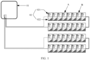
- FIG. 1 is a schematic diagram of a photovoltaic system according to an embodiment of this application.
- the photovoltaic system is configured to convert radiant energy of sunlight into electrical energy.
- the photovoltaic system may include an inverter 01 and a plurality of photovoltaic units 02 connected to the inverter 01.
- the inverter 01 is configured to convert a direct current output by the photovoltaic unit 02 into an alternating current and output the alternating current.
- Each photovoltaic unit 02 includes a controller 021 and one or more photovoltaic modules (also referred to as photovoltaic panels) 022 connected to the controller 021.
- the photovoltaic module 022 is configured to convert radiant energy of sunlight into a direct current.
- the controller 021 is configured to regulate an output status of the one or more photovoltaic modules 022.
- the photovoltaic module 022 may be a photovoltaic (photovoltaic, PV) cell or a photovoltaic panel.
- the controller 021 may have one or more of the following functions: adjusting an output power of the photovoltaic module 022 (in this case, the controller may also be referred to as an optimizer), controlling the photovoltaic module 022 to start or stop output (in this case, the controller may also be referred to as a shutdown module), and monitoring an output status of the photovoltaic module 022 (in this case, the controller may also be referred to as a monitor).
- the controller 021 may regulate a voltage amplitude, a current amplitude, and the like of the direct current output by the photovoltaic module 022, to enable an output power of the photovoltaic module 022 to reach a maximum power, thereby improving utilization of the photovoltaic module 022.
- the controller 021 in each photovoltaic unit 02 is connected to the inverter 01, and each photovoltaic module 022 is connected to the controller 021.
- the controller 021 and the inverter 01 may be connected by using a power line.
- power line communication power line communication, PLC
- PLC power line communication
- the inverter 01 may be referred to as a PLC host, which is also referred to as a central coordinator (central coordinator, CCO); and the controller 021 may be referred to as a PLC slave, which is also referred to as a station (station, STA).
- a connection mentioned in this embodiment of this application may include a direct connection, an indirect connection, or other implementations. This is not specifically limited in this embodiment of this application.
- the photovoltaic unit 02 may further include a shutdown module (not illustrated in FIG. 1 ).
- the shutdown module is configured to connect or disconnect a connection between an output end of the photovoltaic module 022 and the inverter 01.
- the plurality of photovoltaic units 02 of the photovoltaic system may be divided into a plurality of photovoltaic unit groups based on a deployment mode of the photovoltaic system.
- a plurality of photovoltaic units 02 in a same photovoltaic unit group are connected in series to form a direct-current high voltage string.
- the direct-current high voltage string is connected to the inverter 01.
- the inverter 01 is configured to convert a direct current output by the photovoltaic unit 02 into an alternating current and output the alternating current to a power grid.
- information used to represent the deployment mode of the photovoltaic system further needs to be input to the inverter 01.
- information about photovoltaic units 02 included in each photovoltaic unit group is input to the inverter 01, so that the inverter 01 manages the photovoltaic units 02 by photovoltaic unit group based on the information.
- a deployment mode of a photovoltaic system is usually determined manually, and serial numbers of controllers in photovoltaic units included in each photovoltaic unit group are manually input to an inverter.
- this grouping manner is relatively low in efficiency and is prone to errors.
- the controller 021 in each photovoltaic unit 02 is further configured to obtain a power carrier signal sent by a controller 021 in another photovoltaic unit 02 of the plurality of photovoltaic units 02, determine an attenuation reference factor of the power carrier signal based on the obtained power carrier signal, and send the attenuation reference factor to the inverter 01.
- the inverter 01 is further configured to determine, based on the attenuation reference factor, an attenuation degree of the power carrier signal obtained by the controller 021 in each photovoltaic unit 02, and group the plurality of photovoltaic units 02 based on the attenuation degree of the power carrier signal obtained by each photovoltaic unit 02.
- the power carrier signal carries identification information of the controller 021 that sends the power carrier signal, and the attenuation reference factor is used to reflect an attenuation degree of signal attenuation of the power carrier signal in a process of being transmitted, to the controller 021 in the photovoltaic unit 02, from the controller 021 that is in the another photovoltaic unit 02 and that is indicated by the identification information in the power carrier signal.
- the photovoltaic system can implement automatic grouping of the photovoltaic units 02. Compared with the related technology, this can effectively improve efficiency in grouping the photovoltaic units 02 and improve grouping accuracy.
- the inverter 01 when the inverter 01 is configured to group the plurality of photovoltaic units 02 based on the attenuation degree of the power carrier signal obtained by each photovoltaic unit 02, the inverter 01 is specifically configured to: when an attenuation degree of a power carrier signal that is obtained by a controller 021 in a photovoltaic unit 02 and that is sent by a controller 021 in another photovoltaic unit 02 is less than or equal to a reference threshold, determine that the photovoltaic unit 02 and the another photovoltaic unit 02 belong to a same photovoltaic unit group.
- the reference threshold may be specified based on a factor such as actual experience, or may be dynamically determined based on an actual deployment status of the photovoltaic units 02.
- the inverter 01 is further specifically configured to: sort attenuation degrees of power carrier signals that are obtained by controllers 021 in a plurality of photovoltaic units 02 and that are sent by a controller 021 in a same another photovoltaic unit 02, or sort attenuation degrees of power carrier signals that are obtained by a controller 021 in a same photovoltaic unit 02 and that are sent by controllers 021 in a plurality of other photovoltaic units 02; and determine the reference threshold based on a distribution status presented by the plurality of attenuation degrees after the sorting.
- Attenuation degrees corresponding to a plurality of other photovoltaic units 02 are sorted, and the reference threshold is determined based on a result of the sorting.
- the reference threshold can be dynamically determined based on an actual deployment mode of the photovoltaic units 02 in the photovoltaic system, thereby making the reference threshold more recognizable in grouping and improving accuracy in grouping the photovoltaic units 02 based on the reference threshold.
- the attenuation reference factor includes one or more of the following: a signal strength, and a line impedance for transmitting the power carrier signal.
- the power carrier signal that is obtained by a controller 021 in a photovoltaic unit 02 and that is sent by a controller 021 in another photovoltaic unit 02 includes at least one of the following: a power carrier signal that is sent by the controller 021 in the another photovoltaic unit 02 to the inverter 01 and that is obtained through listening by the photovoltaic unit 02; a power carrier signal broadcast by the another photovoltaic unit 02; and a power carrier signal that is sent by the another photovoltaic unit 02 to the photovoltaic unit 02.
- frequency bands used by different photovoltaic units 02 for sending signals may be the same or different.
- a frequency band used for sending a signal may be a frequency band used by a photovoltaic unit 02 for sending a service signal with the inverter 01, for example, may be 75 kilohertz (kHz) to 145 kHz.
- the frequency band may be a frequency band other than the frequency band used for sending a service signal, for example, may be 280 kHz to 300 kHz. This is not specifically limited in this embodiment of this application.
- a sequence in which the plurality of other photovoltaic units 02 send signals successively may be determined based on an actual need. For example, a logical address may be allocated in advance to each photovoltaic unit 02 in the photovoltaic system. In this case, the plurality of other photovoltaic units 02 may send signals in sequence based on the logical addresses of the photovoltaic units 02 in ascending order of the logical addresses.
- the operation of the inverter 01 for determining, based on the attenuation reference factor, the attenuation degree of the power carrier signal obtained by the controller 021 in each photovoltaic unit 02, and grouping the plurality of photovoltaic units 02 based on the attenuation degree of the power carrier signal obtained by each photovoltaic unit 02 may alternatively be performed by any controller 021 in the photovoltaic system.
- a controller 021 in another photovoltaic unit 02 may send an attenuation reference factor of a power carrier signal obtained by the controller 021 to the any controller 021, so that the any controller 021 groups the plurality of photovoltaic units 02 in the photovoltaic system based on the attenuation reference factor.
- the implementation process in the foregoing embodiment in which the inverter 01 groups the photovoltaic units 02 based on attenuation degrees of power carrier signals transmitted between different photovoltaic units 02 is merely an example of an implementation process of a method for grouping photovoltaic units 02 that is provided in the embodiments of this application, but does not exclude that the method for grouping photovoltaic units 02 that is provided in the embodiments of this application has other implementations.
- an execution body of the method for grouping photovoltaic units 02 may alternatively be a controller 021 in a photovoltaic unit 02.
- the controller 021 may obtain attenuation degrees of power carrier signals transmitted between the controller 021 and controllers 021 in other photovoltaic units 02, sort the plurality of attenuation degrees, and then determine, based on a result of the sorting, a photovoltaic unit group to which the photovoltaic unit 02 belongs.
- the controller 021 may obtain an attenuation degree of a power carrier signal transmitted between a controller 021 in another photovoltaic unit 02 and a controller 021 in each of a plurality of other photovoltaic units 02; and then determine, in combination with a result of sorting a plurality of attenuation degrees corresponding to the another photovoltaic unit 02, a photovoltaic unit group to which the photovoltaic unit 02 and the another photovoltaic unit 02 belong.
- a plurality of photovoltaic units 02 in each photovoltaic unit group are connected in series.
- an attenuation degree of a power carrier signal received by one of the two photovoltaic units 02 from the other photovoltaic unit 02 increases.
- the some photovoltaic units 02 may be photovoltaic units 02, in each photovoltaic unit group, located relatively near to a photovoltaic unit connected in series at a middlemost position between a plurality of photovoltaic units 02 in the photovoltaic unit group.
- obtained attenuation degrees of power carrier signals between different photovoltaic units 02 in a same photovoltaic unit group have better aggregation, and obtained attenuation degrees of power carrier signals between photovoltaic units 02 in different photovoltaic unit groups have better dispersion.
- grouping accuracy can be further improved. For example, as shown in FIG. 1 , compared with performing the foregoing grouping process on a photovoltaic unit 02A, performing the foregoing grouping process on a photovoltaic unit 02B can further improve grouping accuracy.
- FIG. 2 is a flowchart of a photovoltaic unit grouping method according to an embodiment of this application. As shown in FIG. 2 , the method may include the following steps.
- Step 201 A controller in a photovoltaic unit obtains a power carrier signal sent by a controller in another photovoltaic unit in a plurality of photovoltaic units.
- controller in the photovoltaic unit may obtain the power carrier signal sent by the controller in the another photovoltaic unit.
- This embodiment of this application is described by using the following several possible implementations as examples.
- the controller in the photovoltaic unit has a function of listening to a power carrier signal.
- the power carrier signal that is obtained by the controller in the photovoltaic unit and that is sent by the controller in the another photovoltaic unit may be a power carrier signal that is sent by the controller in the another photovoltaic unit to another component (for example, an inverter or a controller in a photovoltaic unit different from the another photovoltaic unit) and that is obtained through listening by the controller in the photovoltaic unit.
- the controller in the photovoltaic unit and controllers in a plurality of other photovoltaic units are all connected to the inverter.
- the power carrier signal that is obtained by the controller in the photovoltaic unit and that is sent by the controller in the another photovoltaic unit may be a power carrier signal that is sent by the controller in the another photovoltaic unit to the inverter and that is obtained through listening by the controller in the photovoltaic unit.
- controllers in photovoltaic units each may transmit a power carrier signal to a power line in sequence in a broadcast manner.
- the power carrier signal that is obtained by the controller in the photovoltaic unit and that is sent by the controller in the another photovoltaic unit may be a power carrier signal broadcast by the controller in the another photovoltaic unit.
- the controller in the another photovoltaic unit may directly or indirectly send a power carrier signal to the controller in the photovoltaic unit.
- the power carrier signal that is obtained by the controller in the photovoltaic unit and that is sent by the controller in the another photovoltaic unit may be a power carrier signal sent by the controller in the another photovoltaic unit to the controller in the photovoltaic unit.
- the power carrier signal may carry identification information of the controller that sends the power carrier signal, so that a receive end of the power carrier signal can determine a transmit end of the power carrier signal based on the identification information.
- the identification information of the controller may include one or more of the following: a logical address of the controller, a media access control MAC address of the controller, and a serial number of the controller.
- the logical address of the controller may be allocated to the controller in advance and is used to uniquely identify an address of the controller in the photovoltaic system. For example, when the photovoltaic system includes 100 photovoltaic modules, the inverter may allocate logical addresses to controllers in the 100 photovoltaic modules in advance. The logical addresses of the controllers in the 100 photovoltaic modules may be respectively 1 to 100.
- controllers in all photovoltaic units participating in grouping can send power carrier signals in sequence. Before sending a power carrier signal, a controller in each photovoltaic unit can obtain a power carrier signal sent by a controller, in a photovoltaic unit, that is sending the power carrier signal.
- frequency bands used by controllers in different photovoltaic units for sending power carrier signals may be the same or different.
- a frequency band used for sending a power carrier signal may be a frequency band used by a controller in a photovoltaic unit for sending a service signal with the inverter, for example, may be 75 kilohertz (kHz) to 145 kHz.
- the frequency band may be a frequency band other than the frequency band used for sending a service signal, for example, may be 280 kHz to 300 kHz. This is not specifically limited in this embodiment of this application.
- a sequence in which controllers in the plurality of photovoltaic units in the photovoltaic system send power carrier signals successively may be determined based on an actual need. For example, a logical address may be allocated in advance to each controller in the photovoltaic system. In this case, the controllers in the plurality of photovoltaic units may send power carrier signals in sequence based on the logical addresses of the controllers in ascending order of the logical addresses.
- Step 202 The controller in the photovoltaic unit determines an attenuation reference factor of the power carrier signal based on the obtained power carrier signal, and sends the attenuation reference factor to the inverter.
- the controller in the photovoltaic unit may determine the attenuation reference factor of the power carrier signal based on the obtained power carrier signal, and send the attenuation reference factor of the power carrier signal to the inverter, so that the inverter groups the plurality of photovoltaic units in the photovoltaic system based on the attenuation reference factor of the power carrier signal.
- the attenuation reference factor of the power carrier signal is used to reflect an attenuation degree of signal attenuation of the power carrier signal in a process of being transmitted, to the controller that is in the photovoltaic unit and that obtains the power carrier signal, from the controller that is in the another photovoltaic unit and that is indicated by the identification information carried in the power carrier signal.
- the attenuation reference factor may include one or more of the following: a signal strength, and a line impedance for transmitting the power carrier signal. The following describes an implementation for obtaining the attenuation reference factor.
- the attenuation reference factor of the obtained power carrier signal may be a received strength of the power carrier signal.
- the received strength may be represented by using a received signal strength indicator (received signal strength indicator, RSSI).
- RSSI received signal strength indicator
- a signal receiving impedor for receiving a signal is disposed in the controller.
- the power carrier signal makes the signal receiving impedor generate a voltage drop and a current, and the received strength of the power carrier signal can be determined based on at least one of the voltage drop and the current. Therefore, the received strength of the power carrier signal can be represented by using at least one of the voltage drop and the current.
- a line impedance between the controller that sends the power carrier signal and the controller that receives the power carrier signal is determined by a connection line between the controller that sends the power carrier signal and the controller that receives the power carrier signal.
- a connection manner between components basically does not change. Therefore, after the deployment of the photovoltaic system is completed, statistics about line impedances between controllers are collected, and each controller stores line impedances between the controller and other controllers.
- the line impedance can be queried in either of the two controllers, to obtain the line impedance between the two controllers.
- an attenuation reference factor may be a line impedance of the power line for transmitting the power carrier signal between the different controllers.
- an input voltage of a controller for receiving a power carrier signal, an output voltage of a controller for sending the power carrier signal, and a current on a power line between the two controllers may be separately obtained; then, a voltage difference between the input voltage and the output voltage is obtained; and a line impedance between the two controllers is determined based on a quotient between the voltage difference and the current on the power line. The quotient between the voltage difference and the current on the power line is the line impedance between the two controllers.
- Step 203 The inverter determines, based on the attenuation reference factor, an attenuation degree of a power carrier signal obtained by a controller in each photovoltaic unit.
- the attenuation reference factor is a signal strength (received strength)
- a received strength and a transmitted strength of the power carrier signal may be separately obtained, and a difference between the transmitted strength and the received strength is determined as the attenuation degree of the power carrier signal.
- the inverter, the controller in the photovoltaic unit, and the controller in the another photovoltaic unit may agree on the transmitted strength of the power carrier signal in advance. In this way, after obtaining the received strength of the power carrier signal, the inverter can determine the attenuation degree of the power carrier signal based on the received strength and the agreed transmitted strength.
- the power carrier signal sent by the controller may carry the transmitted strength of the power carrier signal.
- the controller in the photovoltaic unit sends the attenuation reference factor of the power carrier signal to the inverter
- the controller may further extract the transmitted strength of the power carrier signal from the power carrier signal, and send the transmitted strength of the power carrier signal to the inverter, so that the inverter determines the attenuation degree of the power carrier signal based on the received strength and the transmitted strength.
- the attenuation reference factor is a line impedance for transmitting the power carrier signal
- the power carrier signal is transmitted between two controllers by using a power line
- the power carrier signal consumes energy on a power line between the two controllers, causing the power carrier signal to attenuate in a transmission process. Therefore, a line impedance between the two controllers can be used to represent the attenuation degree of the power carrier signal transmitted between the two controllers.
- the attenuation degree of the power carrier signal transmitted between the two controllers may be determined based on the signal strength and the line impedance. For example, a difference between a transmitted strength and a received strength of the power carrier signal transmitted between the two controllers may be obtained, and the line impedance for transmitting the power carrier signal is obtained. Then, a weighted sum of the difference and the line impedance is determined as the attenuation degree of the power carrier signal transmitted between the two controllers.
- Step 204 The inverter sorts attenuation degrees of power carrier signals that are obtained by controllers in a plurality of photovoltaic units and that are sent by a controller in a same another photovoltaic unit, or sorts attenuation degrees of power carrier signals that are obtained by a controller in a same photovoltaic unit and that are sent by controllers in a plurality of other photovoltaic units.
- Controllers in a plurality of photovoltaic units in a same photovoltaic unit group are connected to each other. Therefore, when two photovoltaic units are located in a same photovoltaic unit group, a power carrier signal sent by a controller in one of the two photovoltaic units may be transmitted to a controller in the other one of the two photovoltaic units through a power line between the two photovoltaic units, so that an attenuation degree of the power carrier signal received by the controller in the other photovoltaic unit is relatively small.
- the power carrier signal not only needs to be transmitted through a power line, but also needs to undergo secondary coupling or distributed parameter coupling (for example, mutual inductance coupling) of the inverter. Therefore, when two photovoltaic units are located in different photovoltaic unit groups, an attenuation degree of a power carrier signal transmitted between controllers in the two photovoltaic units is relatively large.
- Attenuation degrees of power carrier signals transmitted between controllers in different pairs of photovoltaic units are also different.
- a difference in attenuation degrees of power carrier signals transmitted between controllers in a same photovoltaic unit group is far smaller than that in attenuation degrees of power carrier signals transmitted between controllers in different photovoltaic unit groups. Therefore, it can be learned that attenuation degrees of power carrier signals transmitted between different controllers in a same photovoltaic unit group present a relatively aggregated distribution status and that attenuation degrees of power carrier signals transmitted between controllers in different photovoltaic unit groups present a relatively dispersed distribution status.
- the inverter may sort the attenuation degrees corresponding to the controllers in different photovoltaic units; and determine, based on a distribution status presented by the plurality of attenuation degrees after the sorting, a reference threshold for distinguishing whether the photovoltaic unit and the another photovoltaic unit are located in a same photovoltaic unit group.
- the plurality of attenuation degrees may be sorted in descending or ascending order of the attenuation degrees. This is not specifically limited in this embodiment of this application.
- the attenuation degrees corresponding to the controllers in different photovoltaic units are sorted, and the reference threshold is determined based on a result of the sorting.
- the reference threshold can be dynamically determined based on an actual deployment mode of the photovoltaic units in the photovoltaic system, thereby making the reference threshold more recognizable in grouping and improving accuracy in grouping the photovoltaic units based on the reference threshold.
- Step 205 The inverter determines the reference threshold based on a distribution status presented by the plurality of attenuation degrees after the sorting.
- the reference threshold may be determined based on the distribution status presented by the plurality of attenuation degrees after the sorting, so that a photovoltaic unit group to which the photovoltaic unit belongs is determined based on the reference threshold in a subsequent grouping process.
- clustering analysis may be performed on the attenuation degrees after the sorting, to obtain a plurality of clustered groups. Each clustered group includes at least one attenuation degree.
- the reference threshold is determined based on an attenuation degree in a clustered group with a smallest average value of attenuation degrees (which is referred to as a smallest clustered group) and an attenuation degree in a second smallest clustered group, where the second smallest clustered group is a clustered group whose average value of attenuation degrees has a smallest difference with the average value of attenuation degrees in the smallest clustered group.
- the average value of attenuation degrees in the smallest clustered group and that in the second smallest clustered group may be separately determined first, and an average value of the two average values is determined as a reference threshold for distinguishing between attenuation degrees in the two clustered groups.
- the reference threshold may be an adjusted value obtained by adjusting the average value of the two average values based on a pre-specified policy.
- the pre-specified policy may be determined based on an application requirement. For example, a value that is 1.3 times the average value of the two average values may be determined as the reference threshold. This is not specifically limited in this embodiment of this application.
- the reference threshold may be a weighted average value of a largest attenuation degree in the smallest clustered group and a smallest attenuation degree in the second smallest clustered group.
- Attenuation degrees in a clustered group meet the following: For any attenuation degree in any clustered group, the clustered group has one or more other attenuation degrees whose difference with the any attenuation degree is less than a first difference threshold, and a difference between two attenuation degrees located in two different clustered groups is greater than a second difference threshold.
- a value of the first difference threshold and a value of the second difference threshold may be determined based on an application requirement, and the value of the first preset difference threshold and the value of the second difference threshold may be equal or unequal. This is not specifically limited in this embodiment of this application.
- the photovoltaic system usually has a plurality of photovoltaic units, in a grouping process, attenuation degrees in a process in which a plurality of photovoltaic units separately transmit power carrier signals to a plurality of other photovoltaic units are usually obtained first.
- the attenuation degrees in the process in which the plurality of photovoltaic units transmit the power carrier signals to the plurality of other photovoltaic units may be separately sorted.
- the reference threshold is determined in combination with a result of sorting corresponding to the plurality of photovoltaic units.
- the plurality results of sorting may be analyzed by using a big data technology, to determine the reference threshold for distinguishing between different photovoltaic unit groups.
- reference threshold may alternatively be pre-specified, for example, based on an empirical value. This is not specifically limited in this embodiment of this application.
- Step 206 The inverter groups the plurality of photovoltaic units based on the attenuation degree of the power carrier signal obtained by each photovoltaic unit and the reference threshold.
- Attenuation degrees of power carrier signals transmitted between controllers in a plurality of photovoltaic units in a same photovoltaic unit group are relatively small. Therefore, when an attenuation degree of a power carrier signal that is obtained by a controller in a photovoltaic unit and that is sent by a controller in another photovoltaic unit is less than or equal to the reference threshold, it can be determined that the photovoltaic unit and the another photovoltaic unit belong to a same photovoltaic unit group.
- each photovoltaic unit group may have an identifier, and the controller in each photovoltaic unit has identification information.
- the information about the photovoltaic units included in the photovoltaic unit groups is recorded, a plurality of photovoltaic units included in a photovoltaic unit group indicated by an identifier may be recorded, and each photovoltaic unit is indicated by the identification information of the controller in the photovoltaic unit.
- the foregoing manner of determining photovoltaic unit groups based on the reference threshold is a possible implementation of determining photovoltaic unit groups, but does not exclude that there may further be other grouping implementations.
- an attenuation value in the clustered group that has the smallest average value is an attenuation degree of a power carrier signal transmitted between controllers in photovoltaic units belonging to a same photovoltaic unit group.
- photovoltaic units corresponding to the attenuation degrees in the clustered group belong to the same photovoltaic unit group.
- the implementation process in the foregoing embodiment in which the inverter groups the photovoltaic units based on attenuation degrees of power carrier signals transmitted between different photovoltaic units is merely an example of an implementation process of the photovoltaic unit grouping method provided in this embodiment of this application, but does not exclude that the photovoltaic unit grouping method provided in this embodiment of this application has other implementations.
- an execution body of the photovoltaic unit grouping method may alternatively be a controller in a photovoltaic unit.
- the controller may obtain attenuation degrees of power carrier signals transmitted between the controller and controllers in other photovoltaic units, sort the plurality of attenuation degrees, and then determine, based on a result of the sorting, a photovoltaic unit group to which the photovoltaic unit belongs.
- the controller may obtain an attenuation degree of a power carrier signal transmitted between a controller in another photovoltaic unit and a controller in each of a plurality of other photovoltaic units; and then determine, in combination with a result of sorting the plurality of attenuation degrees corresponding to the another photovoltaic unit, a photovoltaic unit group to which the photovoltaic unit and the another photovoltaic unit belong.
- the foregoing step 201 to step 206 may be performed on each photovoltaic unit, or the foregoing step 201 to step 206 may be performed on some of the plurality of photovoltaic units, provided that grouping of the plurality of photovoltaic units in the photovoltaic system can be implemented.
- a plurality of photovoltaic units in each photovoltaic unit group are connected in series.
- an attenuation degree of a power carrier signal received by one of the two photovoltaic units from the other photovoltaic unit increases.
- the some photovoltaic units may be photovoltaic units, in each photovoltaic unit group, located relatively near to a photovoltaic unit connected in series at a middlemost position between a plurality of photovoltaic units in the photovoltaic unit group.
- grouping accuracy can be further improved. For example, as shown in FIG. 1 , compared with performing the foregoing step 201 to step 206 on a photovoltaic unit A, performing the foregoing step 201 to step 206 on a photovoltaic unit B can further improve grouping accuracy.
- this embodiment of this application provides a photovoltaic unit grouping method.
- an attenuation reference factor of each power carrier signal transmitted between controllers in different photovoltaic units in the photovoltaic system is obtained, and the attenuation degree of the power carrier signal obtained by the controller in each photovoltaic unit is determined based on the attenuation reference factor.
- the plurality of photovoltaic units are grouped based on the attenuation degree of the power carrier signal obtained by each photovoltaic unit.
- this can implement automatic grouping of the photovoltaic units, and can effectively improve efficiency in grouping the photovoltaic units and improve grouping accuracy, thereby improving operation and maintenance efficiency of the photovoltaic system.
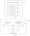
- the photovoltaic unit grouping apparatus 30 may include:
- the grouping module 303 is specifically configured to: when an attenuation degree of a power carrier signal that is obtained by a controller in a photovoltaic unit and that is sent by a controller in another photovoltaic unit is less than or equal to a reference threshold, determine that the photovoltaic unit and the another photovoltaic unit belong to a same photovoltaic unit group.
- the grouping module 303 is further specifically configured to sort attenuation degrees of power carrier signals that are obtained by controllers in a plurality of photovoltaic units and that are sent by a controller in a same another photovoltaic unit, or sort attenuation degrees of power carrier signals that are obtained by a controller in a same photovoltaic unit and that are sent by controllers in a plurality of other photovoltaic units; and determine the reference threshold based on a distribution status presented by the plurality of attenuation degrees after the sorting.
- the attenuation reference factor includes one or more of the following: a signal strength, and a line impedance for transmitting the power carrier signal.
- the power carrier signal that is obtained by the controller in the photovoltaic unit and that is sent by the controller in the another photovoltaic unit includes at least one of the following: a power carrier signal that is sent by the controller in the another photovoltaic unit to the inverter and that is obtained through listening by the controller in the photovoltaic unit; a power carrier signal broadcast by the controller in the another photovoltaic unit; and a power carrier signal that is sent by the controller in the another photovoltaic unit to the controller in the photovoltaic unit.
- this embodiment of this application provides a photovoltaic unit grouping apparatus.
- the obtaining module obtains the attenuation reference factor of each power carrier signal transmitted between the controllers in different photovoltaic units in the photovoltaic system.
- the determining module determines, based on the attenuation reference factor, the attenuation degree of the power carrier signal obtained by the controller in each photovoltaic unit.
- the grouping module groups the plurality of photovoltaic units based on the attenuation degree of the power carrier signal obtained by each photovoltaic unit. Compared with a related technology, this can implement automatic grouping of the photovoltaic units, and can effectively improve efficiency in grouping the photovoltaic units and improve grouping accuracy, thereby improving operation and maintenance efficiency of the photovoltaic system.
- the computing device 400 includes a processor 410, a communications interface 420, and a memory 430.
- the processor 410, the communications interface 420, and the memory 430 are connected to each other by using a bus 440.
- the bus 440 may be classified into an address bus, a data bus, a control bus, and the like. For ease of representation, only one thick line is used to represent the bus in FIG. 4 , but this does not mean that there is only one bus or only one type of bus.
- the memory 430 may include a volatile memory (volatile memory), for example, a random-access memory (random-access memory, RAM).
- the memory 430 may also include a non-volatile memory (non-volatile memory), for example, a flash memory (flash memory), a hard disk drive (hard disk drive, HDD), or a solid-state drive (solid-state drive, SSD).
- the memory 430 may further include a combination of the foregoing types of memories.
- the processor 410 may be a hardware chip and is configured to complete the photovoltaic unit grouping method provided in the embodiments of this application.
- the hardware chip may be an application-specific integrated circuit (application-specific integrated circuit, ASIC), a programmable logic device (programmable logic device, PLD), or a combination thereof.
- the PLD may be a complex programmable logic device (complex programmable logic device, CPLD), a field-programmable gate array (field-programmable gate array, FPGA), generic array logic (generic array logic, GAL), or any combination thereof.
- the processor 410 may be a general-purpose processor, for example, a central processing unit (central processing unit, CPU), a network processor (network processor, NP), or a combination of a CPU and an NP.
- the memory 430 is configured to store program instructions.
- the processor 410 calls the program instructions stored in the memory 430, and can perform one or more steps in the photovoltaic unit grouping method provided in the embodiments of this application or some optional implementations thereof, to enable the computing device 400 to implement the photovoltaic unit grouping method provided in the foregoing method embodiment.
- the processor 410 calls the program instructions stored in the memory 420 to enable the computing device 400 to perform the following steps: obtaining an attenuation reference factor of each power carrier signal transmitted between controllers in different photovoltaic units in a photovoltaic system, and determining an attenuation degree of a power carrier signal obtained by a controller in each photovoltaic unit based on the attenuation reference factor; and grouping a plurality of photovoltaic units based on the attenuation degree of the power carrier signal obtained by each photovoltaic unit.
- the computing device 400 executes computer instructions in the memory 420 to perform the steps, correspondingly refer to corresponding descriptions in the foregoing method embodiment.
- the communications interface 430 may be any one or any combination of the following components with a network access function: a network interface (for example, an Ethernet interface) or a wireless network interface card.
- Embodiment 1 A photovoltaic system, wherein the photovoltaic system comprises an inverter and a plurality of photovoltaic units connected to the inverter, each photovoltaic unit comprises a controller and one or more photovoltaic modules connected to the controller, the photovoltaic module is configured to convert radiant energy of sunlight into a direct current, the controller is configured to regulate an output status of the one or more photovoltaic modules, and the inverter is configured to convert a direct current output by the photovoltaic unit into an alternating current and output the alternating current;
- Embodiment 2 The photovoltaic system according to embodiment 1, wherein when the inverter is configured to group the plurality of photovoltaic units based on the attenuation degree of the power carrier signal obtained by each photovoltaic unit, the inverter is specifically configured to: when an attenuation degree of a power carrier signal that is obtained by a controller in a photovoltaic unit and that is sent by a controller in another photovoltaic unit is less than or equal to a reference threshold, determine that the photovoltaic unit and the another photovoltaic unit belong to a same photovoltaic unit group.
- Embodiment 3 The photovoltaic system according to embodiment 2, wherein when the inverter is configured to group the plurality of photovoltaic units based on the attenuation degree of the power carrier signal obtained by each photovoltaic unit, the inverter is further specifically configured to:
- Embodiment 4 The photovoltaic system according to any one of embodiments 1 to 3, wherein the attenuation reference factor comprises one or more of the following: a signal strength, and a line impedance for transmitting the power carrier signal.
- Embodiment 5 The photovoltaic system according to any one of embodiments 1 to 4, wherein the power carrier signal that is obtained by the controller in the photovoltaic unit and that is sent by the controller in the another photovoltaic unit comprises at least one of the following:
- Embodiment 6 A photovoltaic unit grouping method, wherein the method is applied to a photovoltaic system, the photovoltaic system comprises an inverter and a plurality of photovoltaic units connected to the inverter, the photovoltaic unit comprises a controller and one or more photovoltaic modules connected to the controller, the controller is configured to regulate an output status of the one or more photovoltaic modules, and the method comprises:
- Embodiment 7 The method according to embodiment 6, wherein the grouping the plurality of photovoltaic units based on the attenuation degree of the power carrier signal obtained by each photovoltaic unit comprises: when an attenuation degree of a power carrier signal that is obtained by a controller in a photovoltaic unit and that is sent by a controller in another photovoltaic unit is less than or equal to a reference threshold, determining that the photovoltaic unit and the another photovoltaic unit belong to a same photovoltaic unit group.
- Embodiment 8 The method according to embodiment 7, wherein the grouping the plurality of photovoltaic units based on the attenuation degree of the power carrier signal obtained by each photovoltaic unit further comprises:
- Embodiment 9 The method according to any one of embodiments 6 to 8, wherein the attenuation reference factor comprises one or more of the following: a signal strength, and a line impedance for transmitting the power carrier signal.
- Embodiment 10 The method according to any one of embodiments 6 to 9, wherein the power carrier signal that is obtained by the controller in the photovoltaic unit and that is sent by the controller in the another photovoltaic unit comprises at least one of the following:
- An embodiment of this application further provides a computer-readable storage medium.
- the computer-readable storage medium may be a non-transitory readable storage medium.
- the computer is configured to perform the photovoltaic unit grouping method provided in this application.
- the computer-readable storage medium includes but is not limited to a volatile memory, for example, a random-access memory, or a nonvolatile memory, such as a flash memory, a hard disk drive (hard disk drive, HDD), and a solid-state drive (solid-state drive, SSD).
- This application further provides a computer program product.
- the computer program product includes computer instructions.
- the computing device executes the photovoltaic unit grouping method provided in this application.
- the program may be stored in a computer-readable storage medium.
- the storage medium may be a read-only memory, a magnetic disk, an optical disc, or the like.
Landscapes
- Engineering & Computer Science (AREA)
- Computer Networks & Wireless Communication (AREA)
- Signal Processing (AREA)
- Power Engineering (AREA)
- Supply And Distribution Of Alternating Current (AREA)
- Remote Monitoring And Control Of Power-Distribution Networks (AREA)
- Control Of Electrical Variables (AREA)
Applications Claiming Priority (3)
| Application Number | Priority Date | Filing Date | Title |
|---|---|---|---|
| CN202010186543.2A CN111404480B (zh) | 2020-03-17 | 2020-03-17 | 光伏系统、光伏单元的分组方法、计算设备及存储介质 |
| PCT/CN2021/080077 WO2021185140A1 (fr) | 2020-03-17 | 2021-03-10 | Système photovoltaïque et procédé de regroupement d'unités photovoltaïques |
| EP21770824.7A EP4060895B1 (fr) | 2020-03-17 | 2021-03-10 | Système photovoltaïque et procédé de regroupement d'unités photovoltaïques |
Related Parent Applications (2)
| Application Number | Title | Priority Date | Filing Date |
|---|---|---|---|
| EP21770824.7A Division EP4060895B1 (fr) | 2020-03-17 | 2021-03-10 | Système photovoltaïque et procédé de regroupement d'unités photovoltaïques |
| EP21770824.7A Division-Into EP4060895B1 (fr) | 2020-03-17 | 2021-03-10 | Système photovoltaïque et procédé de regroupement d'unités photovoltaïques |
Publications (4)
| Publication Number | Publication Date |
|---|---|
| EP4366177A2 true EP4366177A2 (fr) | 2024-05-08 |
| EP4366177A3 EP4366177A3 (fr) | 2024-08-28 |
| EP4366177B1 EP4366177B1 (fr) | 2025-09-24 |
| EP4366177C0 EP4366177C0 (fr) | 2025-09-24 |
Family
ID=71430867
Family Applications (2)
| Application Number | Title | Priority Date | Filing Date |
|---|---|---|---|
| EP23218925.8A Active EP4366177B1 (fr) | 2020-03-17 | 2021-03-10 | Système photovoltaïque, procédé de regroupement d'unités photovoltaïques, dispositif informatique et support de stockage |
| EP21770824.7A Active EP4060895B1 (fr) | 2020-03-17 | 2021-03-10 | Système photovoltaïque et procédé de regroupement d'unités photovoltaïques |
Family Applications After (1)
| Application Number | Title | Priority Date | Filing Date |
|---|---|---|---|
| EP21770824.7A Active EP4060895B1 (fr) | 2020-03-17 | 2021-03-10 | Système photovoltaïque et procédé de regroupement d'unités photovoltaïques |
Country Status (7)
| Country | Link |
|---|---|
| US (1) | US12132444B2 (fr) |
| EP (2) | EP4366177B1 (fr) |
| JP (1) | JP7360556B2 (fr) |
| CN (1) | CN111404480B (fr) |
| AU (1) | AU2021237435A1 (fr) |
| ES (1) | ES2985631T3 (fr) |
| WO (1) | WO2021185140A1 (fr) |
Families Citing this family (12)
| Publication number | Priority date | Publication date | Assignee | Title |
|---|---|---|---|---|
| CN111404480B (zh) | 2020-03-17 | 2021-09-14 | 华为技术有限公司 | 光伏系统、光伏单元的分组方法、计算设备及存储介质 |
| CN114094933B (zh) * | 2020-08-24 | 2024-07-30 | 丰郅(上海)新能源科技有限公司 | 支持光伏组件快速关断的关断装置及光伏组件的关断方法 |
| CN116264545B (zh) * | 2022-06-21 | 2023-10-27 | 中兴通讯股份有限公司 | 光伏系统的配置方法、集中管理单元及存储介质 |
| CN115036946B (zh) * | 2022-06-27 | 2026-04-07 | 云南电网有限责任公司电力科学研究院 | 低压台区分相输出功率调节系统、调节方法及存储介质 |
| CN115134333B (zh) * | 2022-09-01 | 2022-12-02 | 广东邦盛新能源科技发展有限公司 | 一种基于光伏发电的快速组网方法、系统及云平台 |
| CN115378052B (zh) * | 2022-10-19 | 2023-03-24 | 杭州禾迈电力电子股份有限公司 | 光伏设备分组方法、管理模块、光伏设备、系统及介质 |
| CN219875200U (zh) * | 2023-02-09 | 2023-10-20 | 华为数字能源技术有限公司 | 一种采用电力线通信的光伏电站 |
| CN116388678A (zh) * | 2023-03-20 | 2023-07-04 | 杭州禾迈电力电子股份有限公司 | 光伏设备的分组方法、分组装置、分组系统及信号注入端 |
| CN118677482A (zh) * | 2023-03-20 | 2024-09-20 | 杭州禾迈电力电子股份有限公司 | 用于确定光伏设备的位置信息的装置、方法及存储介质 |
| CN116505973B (zh) * | 2023-03-29 | 2025-08-22 | 华为数字能源技术有限公司 | 电力线载波通信系统、光伏控制器和子阵控制器 |
| KR20250158350A (ko) * | 2024-04-30 | 2025-11-06 | 한화솔루션 주식회사 | 태양광 발전 시스템의 통신 신호를 제어하는 방법 및 장치 |
| CN118713547B (zh) * | 2024-08-12 | 2025-04-18 | 苏州门海微电子科技有限公司 | 一种光伏系统、光伏组串识别方法、电子设备及存储介质 |
Family Cites Families (14)
| Publication number | Priority date | Publication date | Assignee | Title |
|---|---|---|---|---|
| US9184312B2 (en) * | 2008-07-08 | 2015-11-10 | Mitsubishi Electric Corporation | Solar power generation device |
| US20100198424A1 (en) * | 2009-01-30 | 2010-08-05 | Toru Takehara | Method for reconfigurably connecting photovoltaic panels in a photovoltaic array |
| US8391811B2 (en) * | 2009-12-30 | 2013-03-05 | Triquint Semiconductor, Inc. | Input-power overload-protection circuit |
| CN105471628B (zh) * | 2015-11-17 | 2019-05-31 | 小米科技有限责任公司 | 智能设备分组系统、方法及装置 |
| JP6672010B2 (ja) * | 2016-02-25 | 2020-03-25 | オムロン株式会社 | 電力連携制御システム、電力連携制御方法および電力連携制御プログラム |
| US10599113B2 (en) * | 2016-03-03 | 2020-03-24 | Solaredge Technologies Ltd. | Apparatus and method for determining an order of power devices in power generation systems |
| CN105932964B (zh) * | 2016-05-20 | 2018-03-09 | 华为技术有限公司 | 一种光伏组件检测装置及电力系统 |
| CN109391223B (zh) * | 2017-08-02 | 2020-11-03 | 丰郅(上海)新能源科技有限公司 | 可分时段收发数据的光伏发电系统及其收发数据的方法 |
| CN108494642B (zh) * | 2018-03-29 | 2020-12-11 | 北京小米移动软件有限公司 | 智能设备分组方法、装置、系统及智能设备 |
| CN109194686A (zh) * | 2018-10-15 | 2019-01-11 | 深圳华海通讯股份有限公司 | 一种电力载波通信系统 |
| EP3667902B1 (fr) * | 2018-12-12 | 2026-02-25 | Solaredge Technologies Ltd. | Appareil et procédé permettant de déterminer un ordre de dispositifs de puissance dans des systèmes de production de puissance |
| US11172423B2 (en) * | 2018-12-31 | 2021-11-09 | Itron, Inc. | Solar-powered access point for load balancing network traffic across backhaul networks |
| CN210007670U (zh) * | 2019-05-23 | 2020-01-31 | 台达电子企业管理(上海)有限公司 | 光伏功率优化系统 |
| CN111404480B (zh) * | 2020-03-17 | 2021-09-14 | 华为技术有限公司 | 光伏系统、光伏单元的分组方法、计算设备及存储介质 |
-
2020
- 2020-03-17 CN CN202010186543.2A patent/CN111404480B/zh active Active
-
2021
- 2021-03-10 EP EP23218925.8A patent/EP4366177B1/fr active Active
- 2021-03-10 JP JP2022543023A patent/JP7360556B2/ja active Active
- 2021-03-10 AU AU2021237435A patent/AU2021237435A1/en active Pending
- 2021-03-10 WO PCT/CN2021/080077 patent/WO2021185140A1/fr not_active Ceased
- 2021-03-10 EP EP21770824.7A patent/EP4060895B1/fr active Active
- 2021-03-10 ES ES21770824T patent/ES2985631T3/es active Active
-
2022
- 2022-08-09 US US17/883,744 patent/US12132444B2/en active Active
Also Published As
| Publication number | Publication date |
|---|---|
| WO2021185140A1 (fr) | 2021-09-23 |
| ES2985631T3 (es) | 2024-11-06 |
| JP7360556B2 (ja) | 2023-10-12 |
| US12132444B2 (en) | 2024-10-29 |
| EP4366177A3 (fr) | 2024-08-28 |
| CN111404480B (zh) | 2021-09-14 |
| EP4366177B1 (fr) | 2025-09-24 |
| CN111404480A (zh) | 2020-07-10 |
| EP4060895B1 (fr) | 2024-06-19 |
| JP2023510369A (ja) | 2023-03-13 |
| US20220393642A1 (en) | 2022-12-08 |
| AU2021237435A1 (en) | 2022-07-14 |
| EP4060895A1 (fr) | 2022-09-21 |
| EP4060895A4 (fr) | 2023-01-11 |
| EP4366177C0 (fr) | 2025-09-24 |
Similar Documents
| Publication | Publication Date | Title |
|---|---|---|
| US12132444B2 (en) | Photovoltaic system, photovoltaic unit grouping method, computing device, and storage medium | |
| US11342755B2 (en) | Physical address determining method, apparatus, and device, and storage medium | |
| US11632077B2 (en) | Fault point position determining method and apparatus and photovoltaic system | |
| US11539239B2 (en) | Method and apparatus for obtaining location information of controller | |
| EP4641423A1 (fr) | Procédé, appareil et système de génération de diagramme de disposition pour système de génération d'énergie photovoltaïque, et support de stockage | |
| CN1838011A (zh) | 基于can总线的分布式控制网络智能管理装置及管理方法 | |
| CN112203315B (zh) | 一种铁塔基站异常检测方法及设备 | |
| CN118713547B (zh) | 一种光伏系统、光伏组串识别方法、电子设备及存储介质 | |
| EP4024920A1 (fr) | Procédé, appareil, dispositif et système de détection des sources d'interférences , et support de stockage | |
| CN115905089B (zh) | 基于rs485的混接通信方法、数据采集器及系统 | |
| CN104933124A (zh) | 互联网大数据处理系统 | |
| CN209057227U (zh) | 一种物联网卡批量检测装置 | |
| CN209765325U (zh) | 一种工业互联网控制采集系统 | |
| CN203480509U (zh) | 一种串联供电装置的基于控制模块的串行通讯架构 | |
| CN112787396B (zh) | 源网荷精准控制系统中终端自动精准识别系统及方法 | |
| CN118828644A (zh) | 基站能效异常检测方法、装置、检测设备及可读存储介质 | |
| CN112583727B (zh) | 一种数据采集方法和设备 | |
| CN105005498A (zh) | 互联网信息处理平台 | |
| CN118890005A (zh) | 光伏系统、新增单元组串识别方法、存储介质及电子设备 | |
| CN121771241A (zh) | 组件控制器的自组网方法及相关设备 | |
| CN105022292A (zh) | 因特网数据处理系统 | |
| CN110649887A (zh) | 一种光伏发电管理方法 | |
| CN110971269A (zh) | 应用于配电故障指示系统的无线跳频自组网方法 | |
| CN121771239A (zh) | 组件控制器的自组网方法及相关设备 |
Legal Events
| Date | Code | Title | Description |
|---|---|---|---|
| PUAI | Public reference made under article 153(3) epc to a published international application that has entered the european phase |
Free format text: ORIGINAL CODE: 0009012 |
|
| STAA | Information on the status of an ep patent application or granted ep patent |
Free format text: STATUS: REQUEST FOR EXAMINATION WAS MADE |
|
| 17P | Request for examination filed |
Effective date: 20240131 |
|
| AC | Divisional application: reference to earlier application |
Ref document number: 4060895 Country of ref document: EP Kind code of ref document: P |
|
| AK | Designated contracting states |
Kind code of ref document: A2 Designated state(s): AL AT BE BG CH CY CZ DE DK EE ES FI FR GB GR HR HU IE IS IT LI LT LU LV MC MK MT NL NO PL PT RO RS SE SI SK SM TR |
|
| REG | Reference to a national code |
Ref country code: DE Ref legal event code: R079 Free format text: PREVIOUS MAIN CLASS: H04B0003480000 Ipc: H02J0001080000 Ref country code: DE Ref legal event code: R079 Ref document number: 602021039359 Country of ref document: DE Free format text: PREVIOUS MAIN CLASS: H04B0003480000 Ipc: H02J0001080000 |
|
| PUAL | Search report despatched |
Free format text: ORIGINAL CODE: 0009013 |
|
| AK | Designated contracting states |
Kind code of ref document: A3 Designated state(s): AL AT BE BG CH CY CZ DE DK EE ES FI FR GB GR HR HU IE IS IT LI LT LU LV MC MK MT NL NO PL PT RO RS SE SI SK SM TR |
|
| RIC1 | Information provided on ipc code assigned before grant |
Ipc: H04B 3/54 20060101ALN20240725BHEP Ipc: H04B 3/48 20150101ALI20240725BHEP Ipc: H02S 50/00 20140101ALI20240725BHEP Ipc: H02J 13/00 20060101ALI20240725BHEP Ipc: H02J 1/08 20060101AFI20240725BHEP |
|
| GRAP | Despatch of communication of intention to grant a patent |
Free format text: ORIGINAL CODE: EPIDOSNIGR1 |
|
| STAA | Information on the status of an ep patent application or granted ep patent |
Free format text: STATUS: GRANT OF PATENT IS INTENDED |
|
| RIC1 | Information provided on ipc code assigned before grant |
Ipc: H04B 3/54 20060101ALN20250509BHEP Ipc: H04B 3/48 20150101ALI20250509BHEP Ipc: H02S 50/00 20140101ALI20250509BHEP Ipc: H02J 13/00 20060101ALI20250509BHEP Ipc: H02J 1/08 20060101AFI20250509BHEP |
|
| INTG | Intention to grant announced |
Effective date: 20250526 |
|
| GRAS | Grant fee paid |
Free format text: ORIGINAL CODE: EPIDOSNIGR3 |
|
| GRAA | (expected) grant |
Free format text: ORIGINAL CODE: 0009210 |
|
| STAA | Information on the status of an ep patent application or granted ep patent |
Free format text: STATUS: THE PATENT HAS BEEN GRANTED |
|
| AC | Divisional application: reference to earlier application |
Ref document number: 4060895 Country of ref document: EP Kind code of ref document: P |
|
| AK | Designated contracting states |
Kind code of ref document: B1 Designated state(s): AL AT BE BG CH CY CZ DE DK EE ES FI FR GB GR HR HU IE IS IT LI LT LU LV MC MK MT NL NO PL PT RO RS SE SI SK SM TR |
|
| REG | Reference to a national code |
Ref country code: GB Ref legal event code: FG4D |
|
| REG | Reference to a national code |
Ref country code: CH Ref legal event code: EP |
|
| REG | Reference to a national code |
Ref country code: DE Ref legal event code: R096 Ref document number: 602021039359 Country of ref document: DE |
|
| REG | Reference to a national code |
Ref country code: IE Ref legal event code: FG4D |
|
| U01 | Request for unitary effect filed |
Effective date: 20250924 |
|
| U07 | Unitary effect registered |
Designated state(s): AT BE BG DE DK EE FI FR IT LT LU LV MT NL PT RO SE SI Effective date: 20251001 |
|
| PG25 | Lapsed in a contracting state [announced via postgrant information from national office to epo] |
Ref country code: NO Free format text: LAPSE BECAUSE OF FAILURE TO SUBMIT A TRANSLATION OF THE DESCRIPTION OR TO PAY THE FEE WITHIN THE PRESCRIBED TIME-LIMIT Effective date: 20251224 |
|
| PG25 | Lapsed in a contracting state [announced via postgrant information from national office to epo] |
Ref country code: HR Free format text: LAPSE BECAUSE OF FAILURE TO SUBMIT A TRANSLATION OF THE DESCRIPTION OR TO PAY THE FEE WITHIN THE PRESCRIBED TIME-LIMIT Effective date: 20250924 |
|
| PG25 | Lapsed in a contracting state [announced via postgrant information from national office to epo] |
Ref country code: GR Free format text: LAPSE BECAUSE OF FAILURE TO SUBMIT A TRANSLATION OF THE DESCRIPTION OR TO PAY THE FEE WITHIN THE PRESCRIBED TIME-LIMIT Effective date: 20251225 |
|
| PG25 | Lapsed in a contracting state [announced via postgrant information from national office to epo] |
Ref country code: RS Free format text: LAPSE BECAUSE OF FAILURE TO SUBMIT A TRANSLATION OF THE DESCRIPTION OR TO PAY THE FEE WITHIN THE PRESCRIBED TIME-LIMIT Effective date: 20251224 |
|
| PG25 | Lapsed in a contracting state [announced via postgrant information from national office to epo] |
Ref country code: SM Free format text: LAPSE BECAUSE OF FAILURE TO SUBMIT A TRANSLATION OF THE DESCRIPTION OR TO PAY THE FEE WITHIN THE PRESCRIBED TIME-LIMIT Effective date: 20250924 |
|
| PG25 | Lapsed in a contracting state [announced via postgrant information from national office to epo] |
Ref country code: ES Free format text: LAPSE BECAUSE OF FAILURE TO SUBMIT A TRANSLATION OF THE DESCRIPTION OR TO PAY THE FEE WITHIN THE PRESCRIBED TIME-LIMIT Effective date: 20250924 |
|
| PG25 | Lapsed in a contracting state [announced via postgrant information from national office to epo] |
Ref country code: IS Free format text: LAPSE BECAUSE OF FAILURE TO SUBMIT A TRANSLATION OF THE DESCRIPTION OR TO PAY THE FEE WITHIN THE PRESCRIBED TIME-LIMIT Effective date: 20260124 |
|
| PG25 | Lapsed in a contracting state [announced via postgrant information from national office to epo] |
Ref country code: CZ Free format text: LAPSE BECAUSE OF FAILURE TO SUBMIT A TRANSLATION OF THE DESCRIPTION OR TO PAY THE FEE WITHIN THE PRESCRIBED TIME-LIMIT Effective date: 20250924 |
|
| PG25 | Lapsed in a contracting state [announced via postgrant information from national office to epo] |
Ref country code: PL Free format text: LAPSE BECAUSE OF FAILURE TO SUBMIT A TRANSLATION OF THE DESCRIPTION OR TO PAY THE FEE WITHIN THE PRESCRIBED TIME-LIMIT Effective date: 20250924 |
|
| PG25 | Lapsed in a contracting state [announced via postgrant information from national office to epo] |
Ref country code: SK Free format text: LAPSE BECAUSE OF FAILURE TO SUBMIT A TRANSLATION OF THE DESCRIPTION OR TO PAY THE FEE WITHIN THE PRESCRIBED TIME-LIMIT Effective date: 20250924 |