EP4366186A1 - Verfahren zur rückkopplung von kanalstatusinformationen und kommunikationsvorrichtung - Google Patents
Verfahren zur rückkopplung von kanalstatusinformationen und kommunikationsvorrichtung Download PDFInfo
- Publication number
- EP4366186A1 EP4366186A1 EP22851803.1A EP22851803A EP4366186A1 EP 4366186 A1 EP4366186 A1 EP 4366186A1 EP 22851803 A EP22851803 A EP 22851803A EP 4366186 A1 EP4366186 A1 EP 4366186A1
- Authority
- EP
- European Patent Office
- Prior art keywords
- csi
- channel
- antenna port
- pieces
- antenna ports
- Prior art date
- Legal status (The legal status is an assumption and is not a legal conclusion. Google has not performed a legal analysis and makes no representation as to the accuracy of the status listed.)
- Pending
Links
- 238000000034 method Methods 0.000 title claims abstract description 98
- 238000004891 communication Methods 0.000 title claims abstract description 70
- 239000011159 matrix material Substances 0.000 claims abstract description 100
- 239000013598 vector Substances 0.000 claims abstract description 94
- 238000005259 measurement Methods 0.000 claims abstract description 42
- 238000004590 computer program Methods 0.000 claims description 15
- 230000006870 function Effects 0.000 description 85
- 230000005540 biological transmission Effects 0.000 description 18
- 238000010586 diagram Methods 0.000 description 16
- 238000012545 processing Methods 0.000 description 11
- 230000011664 signaling Effects 0.000 description 11
- 238000001228 spectrum Methods 0.000 description 10
- 238000005516 engineering process Methods 0.000 description 8
- 208000037918 transfusion-transmitted disease Diseases 0.000 description 8
- 238000013507 mapping Methods 0.000 description 6
- AFEHBIGDWIGTEH-AQRCPPRCSA-N semax Chemical compound C([C@H](NC(=O)[C@H](CCC(O)=O)NC(=O)[C@@H](N)CCSC)C(=O)N[C@@H](CC=1C=CC=CC=1)C(=O)N1[C@@H](CCC1)C(=O)NCC(=O)N1[C@@H](CCC1)C(O)=O)C1=CNC=N1 AFEHBIGDWIGTEH-AQRCPPRCSA-N 0.000 description 6
- 230000009286 beneficial effect Effects 0.000 description 5
- 230000003595 spectral effect Effects 0.000 description 4
- 238000010295 mobile communication Methods 0.000 description 3
- 230000006978 adaptation Effects 0.000 description 2
- 230000003321 amplification Effects 0.000 description 2
- 238000003199 nucleic acid amplification method Methods 0.000 description 2
- 230000000737 periodic effect Effects 0.000 description 2
- 235000019527 sweetened beverage Nutrition 0.000 description 2
- 102100022734 Acyl carrier protein, mitochondrial Human genes 0.000 description 1
- 101000678845 Homo sapiens Acyl carrier protein, mitochondrial Proteins 0.000 description 1
- 230000003044 adaptive effect Effects 0.000 description 1
- 230000003190 augmentative effect Effects 0.000 description 1
- 238000004422 calculation algorithm Methods 0.000 description 1
- 238000004364 calculation method Methods 0.000 description 1
- 238000013500 data storage Methods 0.000 description 1
- 238000013461 design Methods 0.000 description 1
- 230000000694 effects Effects 0.000 description 1
- 230000003287 optical effect Effects 0.000 description 1
- 239000004065 semiconductor Substances 0.000 description 1
- 238000007493 shaping process Methods 0.000 description 1
- XLYOFNOQVPJJNP-UHFFFAOYSA-N water Substances O XLYOFNOQVPJJNP-UHFFFAOYSA-N 0.000 description 1
Images




Classifications
-
- H—ELECTRICITY
- H04—ELECTRIC COMMUNICATION TECHNIQUE
- H04B—TRANSMISSION
- H04B7/00—Radio transmission systems, i.e. using radiation field
- H04B7/02—Diversity systems; Multi-antenna system, i.e. transmission or reception using multiple antennas
- H04B7/04—Diversity systems; Multi-antenna system, i.e. transmission or reception using multiple antennas using two or more spaced independent antennas
- H04B7/06—Diversity systems; Multi-antenna system, i.e. transmission or reception using multiple antennas using two or more spaced independent antennas at the transmitting station
- H04B7/0613—Diversity systems; Multi-antenna system, i.e. transmission or reception using multiple antennas using two or more spaced independent antennas at the transmitting station using simultaneous transmission
- H04B7/0615—Diversity systems; Multi-antenna system, i.e. transmission or reception using multiple antennas using two or more spaced independent antennas at the transmitting station using simultaneous transmission of weighted versions of same signal
- H04B7/0619—Diversity systems; Multi-antenna system, i.e. transmission or reception using multiple antennas using two or more spaced independent antennas at the transmitting station using simultaneous transmission of weighted versions of same signal using feedback from receiving side
- H04B7/0621—Feedback content
- H04B7/0626—Channel coefficients, e.g. channel state information [CSI]
-
- H—ELECTRICITY
- H04—ELECTRIC COMMUNICATION TECHNIQUE
- H04B—TRANSMISSION
- H04B7/00—Radio transmission systems, i.e. using radiation field
- H04B7/02—Diversity systems; Multi-antenna system, i.e. transmission or reception using multiple antennas
- H04B7/04—Diversity systems; Multi-antenna system, i.e. transmission or reception using multiple antennas using two or more spaced independent antennas
- H04B7/0413—MIMO systems
- H04B7/0456—Selection of precoding matrices or codebooks, e.g. using matrices antenna weighting
- H04B7/0478—Special codebook structures directed to feedback optimisation
-
- H—ELECTRICITY
- H04—ELECTRIC COMMUNICATION TECHNIQUE
- H04B—TRANSMISSION
- H04B7/00—Radio transmission systems, i.e. using radiation field
- H04B7/02—Diversity systems; Multi-antenna system, i.e. transmission or reception using multiple antennas
- H04B7/04—Diversity systems; Multi-antenna system, i.e. transmission or reception using multiple antennas using two or more spaced independent antennas
- H04B7/06—Diversity systems; Multi-antenna system, i.e. transmission or reception using multiple antennas using two or more spaced independent antennas at the transmitting station
- H04B7/0686—Hybrid systems, i.e. switching and simultaneous transmission
- H04B7/0691—Hybrid systems, i.e. switching and simultaneous transmission using subgroups of transmit antennas
-
- H—ELECTRICITY
- H04—ELECTRIC COMMUNICATION TECHNIQUE
- H04L—TRANSMISSION OF DIGITAL INFORMATION, e.g. TELEGRAPHIC COMMUNICATION
- H04L1/00—Arrangements for detecting or preventing errors in the information received
- H04L1/02—Arrangements for detecting or preventing errors in the information received by diversity reception
- H04L1/06—Arrangements for detecting or preventing errors in the information received by diversity reception using space diversity
-
- H—ELECTRICITY
- H04—ELECTRIC COMMUNICATION TECHNIQUE
- H04L—TRANSMISSION OF DIGITAL INFORMATION, e.g. TELEGRAPHIC COMMUNICATION
- H04L5/00—Arrangements affording multiple use of the transmission path
-
- H—ELECTRICITY
- H04—ELECTRIC COMMUNICATION TECHNIQUE
- H04L—TRANSMISSION OF DIGITAL INFORMATION, e.g. TELEGRAPHIC COMMUNICATION
- H04L5/00—Arrangements affording multiple use of the transmission path
- H04L5/003—Arrangements for allocating sub-channels of the transmission path
- H04L5/0053—Allocation of signalling, i.e. of overhead other than pilot signals
- H04L5/0057—Physical resource allocation for CQI
-
- H—ELECTRICITY
- H04—ELECTRIC COMMUNICATION TECHNIQUE
- H04W—WIRELESS COMMUNICATION NETWORKS
- H04W24/00—Supervisory, monitoring or testing arrangements
- H04W24/10—Scheduling measurement reports ; Arrangements for measurement reports
Definitions
- This application relates to the field of communication technologies, and in particular, to a channel state information feedback method and a communication apparatus.
- a multiple-input multiple-output (multiple-input multiple-output, MIMO) technology is outstanding because the technology can use limited spectrum resources to greatly improve transmission reliability and increase a transmission capacity.
- the MIMO technology is mainly implemented in digital domain, and includes digital domain precoding and digital domain beamforming.
- one antenna element may correspond to one digital channel.
- the digital channel may include a whole set of processing components including a digital-to-analog converter/analog-to-digital converter (digital-to-analog converter/analog-to-digital converter, DAC/ADC), a filter (filter), and a power amplifier (power amplifier, PA).
- a frequency of a radio frequency signal is excessively high, and a quantity of antenna elements that can be deployed on a base station side is excessively large, for example, 1024 or 2048.
- an extremely high frequency of the radio frequency signal and an extremely large available bandwidth cause increasingly high costs of the components such as the DAC/ADC, the filter, and the PA.
- one digital channel corresponds to a plurality of analog channels, and each analog channel corresponds to one or more antenna elements. In this way, a quantity of digital channels is reduced, to reduce deployment costs and reduce the size of the base station.
- the base station may shut down some transmit and receive channels (for example, digital channels or analog channels) to reduce power consumption of components on these channels.
- the base station may use more time-frequency resources to ensure that an average transmission rate does not decrease, to ensure data transmission performance.
- the transmit and receive channel is associated with some antenna elements, and the transmit and receive channel is represented as an antenna port in a protocol. Therefore, channel shutdown is also referred to as "antenna port shutdown” or “antenna shutdown” for short.
- channel shutdown used in the product is semi-static. To be specific, a channel shutdown pattern (pattern) is selected based on a traffic volume prediction within a time period, and service transmission is performed based on the channel shutdown pattern.
- TTI transmission time interval
- service arrival fluctuates.
- a traffic volume in some TTIs is large.
- shutdown of an excessively large quantity of channels limits a transmission rate.
- a traffic volume in other TTIs is small.
- an energy saving gain cannot be maximized due to shutdown of an excessively small quantity of channels. Therefore, an on-demand and dynamic channel shutdown solution is proposed for each TTI.
- Dynamic channel shutdown is also called on-demand channel shutdown.
- a core idea of dynamic channel shutdown is that in each TTI, the base station maximizes, on a premise of ensuring a service transmission requirement, a channel shutdown proportion based on a traffic volume to be transmitted in the TTI, to obtain a maximum instantaneous energy saving gain without affecting user experience.
- traffic volumes in different TTIs are different, expected channel shutdown patterns are also different. Therefore, the base station cannot send a downlink pilot signal (namely, a downlink reference signal) in advance based on the channel shutdown pattern to enable UE to measure and feed back channel state information (channel state information, CSI) in the channel shutdown pattern.
- CSI channel state information
- a base station predefines several antenna channel patterns, and then sends a downlink pilot signal in each channel shutdown pattern in advance, and a terminal device measures and reports CSI respectively corresponding to a plurality of downlink pilot signals.
- the base station may separately send the downlink pilot signals in a slot 0 based on five channel shutdown patterns, and the terminal device measures and reports the CSI respectively corresponding to the plurality of downlink pilot signals in the slot 0.
- a network device may select, from CSI corresponding to the five channel shutdown patterns in a slot 1 to a slot 10, CSI corresponding to a corresponding channel shutdown pattern for data transmission. It is clear that, this causes a problem that overheads of the downlink pilot signals increase linearly.
- Embodiments of this application provide a channel state information feedback method and a communication apparatus, to determine more pieces of CSI in a channel shutdown pattern based on limited downlink pilot signal overheads.
- this application provides a channel state information feedback method.
- An example in which a terminal device performs the method is used.
- the method includes: The terminal device receives reference signal configuration information from a network device, where the reference signal configuration information is used for configuring N 1 reference signals, N 1 is a positive integer, the N 1 reference signals correspond to N antenna ports, and N is an integer greater than 1; obtains K 1 first channel vectors based on K 1 combination matrices and measurement results of the N 1 reference signals on the N antenna ports, where an i th combination matrix in the K 1 combination matrices is used for combining the N antenna ports into M i antenna ports, an i th first channel vector in the K 1 first channel vectors is a channel vector on the M i antenna ports, M i is less than or equal to N , M i is a positive integer, K 1 is a positive integer, and 1 ⁇ i ⁇ K 1 ; obtains K 1 pieces of channel state information CSI based on the K 1 first channel vectors; and
- the N antenna ports may correspond to N analog channel subarrays.
- One digital channel corresponds to a plurality of analog channel subarrays, and one digital channel corresponds to one antenna port.
- One combination matrix is used for combining the N analog channel subarrays into a plurality of digital channels. Therefore, one combination matrix is in one-to-one correspondence with one analog channel shutdown pattern.
- CSI corresponding to a plurality of digital channels in an analog channel shutdown pattern may be obtained based on a combination matrix corresponding to the analog channel shutdown pattern and measurement results on all of the analog channel subarrays.
- the network device does not need to send a downlink reference signal in each analog channel shutdown pattern, but needs to send only one common downlink reference signal, and the terminal device can obtain more pieces of CSI in the analog channel shutdown pattern based on limited pilot overheads.
- the N antenna ports may correspond to N digital channels. After some digital channels are closed, corresponding antenna elements may be switched to remaining digital channels, so that a quantity of available antenna elements can be reserved to maintain a maximum antenna array gain.
- One combination matrix is used for combining the N digital channels. To be specific, the some digital channels are shut down and the corresponding antenna elements are switched to the remaining digital channels. Therefore, one combination matrix is in one-to-one correspondence with one digital channel shutdown pattern.
- CSI in a digital channel shutdown pattern may be obtained based on a combination matrix corresponding to the digital channel shutdown pattern and measurement results on all of the digital channels. It can be learned that, according to the method described in the first aspect, the network device does not need to send a downlink reference signal in each digital channel shutdown pattern, but needs to send only one common downlink reference signal, and the terminal device can obtain more pieces of CSI in the digital channel shutdown pattern based on limited pilot overheads.
- this application provides a channel state information feedback method.
- An example in which a network device performs the method is used.
- the method includes: The network device sends reference signal configuration information to a terminal device, where the reference signal configuration information is used for configuring N 1 reference signals, N 1 is a positive integer, the N 1 reference signals correspond to N antenna ports, and N is an integer greater than 1; sends the N 1 reference signals on the N antenna ports; and receives K 2 pieces of channel state information CSI in K 1 pieces of CSI from the terminal device, where K 2 is a positive integer less than or equal to K 1 , the K 1 pieces of CSI are obtained based on K 1 first channel vectors, the K 1 first channel vectors are obtained based on K 1 combination matrices and measurement results of the N 1 reference signals on the N antenna ports, an i th combination matrix in the K 1 combination matrices is used for combining the N antenna ports into M i antenna ports, an i th first channel vector in the K 1 first channel vectors is a channel
- the M i antenna ports correspond to M i digital channels
- the N antenna ports correspond to N analog channel subarrays
- M i is less than N .
- the M i antenna ports correspond to M i remaining activated digital channels in one digital channel shutdown pattern
- the N antenna ports correspond to all of the N digital channels
- M i is less than N.
- the K 1 pieces of CSI include CSI# j
- the CSI# j includes a precoding matrix indicator PMI
- the PMI is used for determining a precoding matrix, recommended by the terminal device, of the network device on M j antenna ports corresponding to CSI# j in CSI# j.
- the i th combination matrix is used for combining the N antenna ports into the M i antenna ports means that the i th combination matrix is used for combining second channel vectors into the first channel vector on the M i antenna ports, and the second channel vectors are channel vectors that are on the N antenna ports and that are obtained based on the measurement results on the N antenna ports.
- one combination matrix may be used for obtaining a channel vector in one channel shutdown pattern.
- the antenna ports are grouped, and different antenna port groups correspond to different time domain positions, so that when the network device sends the reference signal in the N 2 antenna port groups, analog channel subarray switching can be more easily implemented.
- N 2 N 1 ; or N 2 / N 1 is an integer greater than 1.
- one reference signal may correspond to one antenna port group, or a plurality of antenna port groups may correspond to one reference signal. This helps reduce reference signal overheads.
- the second channel vector is H 2
- the i th first channel vector is H 1 i
- H 1 i A i ⁇ H 2
- a i is the i th combination matrix
- a i [ a m,n ] 1 ⁇ m ⁇ M i ,1 ⁇ n ⁇ N
- a m,n is an element in an m th row and an n th column of the combination matrix A i
- a m,n represents a combination weight from an n th antenna port in the N antenna ports to an m th combined port in the M i antenna ports.
- a m,n is 1 or 0; or a m,n is 0 or a m , and a m is protocol-predefined or a m is configured by the network device.
- a m,n 1 and a m,n 2 exist in A i , a m,n 1 > 0, a m,n 2 > 0, and n 1 is not equal to n 2 .
- one combined antenna port needs to be obtained by combining at least two antenna ports in the N antenna ports.
- first indication information is received from the network device, where the first indication information indicates the K 1 combination matrices.
- the K 1 combination matrices are not fixed, and may be indicated by the network device. In this way, the terminal device can more flexibly determine CSI in different channel shutdown patterns.
- first indication information is sent to the terminal device, where the first indication information indicates the K 1 combination matrices.
- the K 1 combination matrices are not fixed, and may be indicated by the network device. In this way, the terminal device can more flexibly determine CSI in different channel shutdown patterns.
- the K 1 combination matrices are K 1 combination matrices in K combination matrices
- the first indication information indicates sequence numbers of the K 1 combination matrices in a set including the K combination matrices, where the K combination matrices are protocol-predefined or indicated by the network device by using second indication information, and K is an integer greater than or equal to K 1 .
- the network device may indicate a plurality of combination matrices to the terminal device in advance, and subsequently flexibly indicate, by using the first indication information and as required, a combination matrix to be used by the terminal device. Therefore, based on this possible implementation, flexibility of indicating the combination matrix by the network device can be improved.
- K 2 is equal to K 1 .
- the terminal device feeds back all of CSI determined by the terminal device.
- K 2 is less than K 1 , where
- the M i combined antenna ports are in one-to-one correspondence with the M i digital channels
- the N antenna ports are in one-to-one correspondence with the N analog channel subarrays
- one digital channel corresponds to one or more analog channel subarrays.
- this application provides a communication apparatus.
- the communication apparatus may be a terminal device, an apparatus in the terminal device, or an apparatus that can be used together with the terminal device.
- the communication apparatus may alternatively be a chip system.
- the communication apparatus may perform the method according to the first aspect.
- a function of the communication apparatus may be implemented by hardware, or may be implemented by hardware by executing corresponding software.
- the hardware or the software includes one or more units or modules corresponding to the function.
- the unit or the module may be software and/or hardware.
- this application provides a communication apparatus.
- the communication apparatus may be a network device, an apparatus in the network device, or an apparatus that can be used together with the network device.
- the communication apparatus may alternatively be a chip system.
- the communication apparatus may perform the method according to the second aspect.
- a function of the communication apparatus may be implemented by hardware, or may be implemented by hardware by executing corresponding software.
- the hardware or the software includes one or more units or modules corresponding to the function.
- the unit or the module may be software and/or hardware.
- this application provides a communication apparatus.
- the communication apparatus includes a processor and an interface circuit.
- the interface circuit is configured to: receive a signal from a communication apparatus other than the communication apparatus and transmit the signal to the processor, or send a signal from the processor to a communication apparatus other than the communication apparatus.
- the processor is configured to implement the method according to the first aspect or the second aspect by using a logic circuit or by executing code instructions.
- this application provides a computer-readable storage medium, where the storage medium stores a computer program or instructions, and when the computer program or the instructions are executed by a communication apparatus, the method according to the first aspect or the second aspect is implemented.
- this application provides a computer program product including instructions.
- the communication apparatus When a communication apparatus reads and executes the instructions, the communication apparatus is enabled to perform the method according to any one of the first aspect or the second aspect.
- this application provides a communication system, including the communication apparatus configured to perform the method according to the first aspect and the communication apparatus configured to perform the method according to the second aspect.
- This application mainly focuses on an antenna port of a downlink reference signal, for example, a channel state information-reference signal (CSI-reference signal, CSI-RS) antenna port.
- CSI-reference signal CSI-reference signal
- the base station enables the CSI-RS antenna port and the digital channel on the radio frequency unit to be in one-to-one correspondence.
- UE may obtain a channel matrix on each digital channel on the radio frequency unit by measuring a CSI-RS.
- the standard also supports sending a pre-coded CSI-RS (pre-coded CSI-RS).
- the radio frequency unit has 32 digital channels, but may send 16-port CSI-RSs.
- Each CSI-RS port corresponds to one logical port, and each logical port is associated with one mapping vector of 1 to 32 digital channels.
- the pre-coded CSI-RSs are mostly used in a scenario in which a base station end has learned of information about some or all of channels. For example, in a TDD system, the base station has obtained a channel matrix based on an SRS.
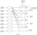
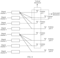
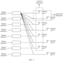
- one low-frequency sending apparatus includes eight digital channels that correspond to eight antenna ports, and may include the following four modes of digital channel shutdown and antenna switching.
- Mode 1 Shut down half of the channels in a vertical dimension, and switch the corresponding antennas to the remaining half of the channels in the vertical dimension, as shown in FIG. 4 .
- Mode 2 Shut down three-quarters of the channels in a vertical dimension, and switch the corresponding antennas to the remaining quarter of the channels in the vertical dimension, as shown in FIG. 5 .
- Mode 3 Shut down half of the channels in a vertical dimension and half of the channels in a horizontal dimension, and switch the corresponding antennas to the remaining quarter of the channels, as shown in FIG. 6 .
- Mode 4 Shut down three-quarters of the channels in a vertical dimension and half of the channels in a horizontal dimension, and switch the corresponding antennas to the remaining one-eighth of the channels, as shown in FIG. 7 .
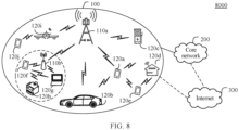
- FIG. 8 is a schematic diagram of an architecture of a communication system 8000 to which an embodiment of this application is applied.
- the communication system includes a radio access network 100 and a core network 200.
- the communication system 8000 may further include the Internet 300.
- the radio access network 100 may include at least one radio access network device (for example, 110a and 110b in FIG. 8 ), and may further include at least one terminal (for example, 120a to 120j in FIG. 8 ).
- the terminal is connected to the radio access network device in a wireless manner, and the radio access network device is connected to the core network in a wireless or wired manner.
- a core network device and the radio access network device may be independent and different physical devices; functions of the core network device and logical functions of the radio access network device are integrated into a same physical device; or some functions of the core network device and some functions of the radio access network device are integrated into one physical device.
- the wired or wireless manner may be used for connection between the terminals and between the radio access network devices.
- FIG. 8 is only a schematic diagram.
- the communication system may further include another network device, for example, may further include a wireless relay device and a wireless backhaul device, which are not shown in FIG. 8 .
- the radio access network device may be a base station (base station), an evolved NodeB (evolved NodeB, eNodeB), a transmission reception point (transmission reception point, TRP), a next generation NodeB (next generation NodeB, gNB) in a 5 th generation (5 th generation, 5G) mobile communication system, a next generation NodeB in a 6 th generation (6 th generation, 6G) mobile communication system, a base station in a future mobile communication system, an access node in a Wi-Fi system, or the like; or the radio access network device may be a module or unit that completes some functions of the base station, for example, may be a central unit (central unit, CU), or may be a distributed unit (distributed unit, DU).
- the CU herein completes functions of a radio resource control protocol and a packet data convergence protocol (packet data convergence protocol, PDCP) of the base station, and may further complete a function of a service data adaptation protocol (service data adaptation protocol, SDAP).
- the DU completes functions of a radio link control layer and a medium access control (medium access control, MAC) layer of the base station, and may further complete functions of some or all of physical layers.
- 3 rd generation partnership project 3 rd generation partnership project, 3GPP.
- the radio access network device may be a macro base station (for example, 110a in FIG. 8 ), or may be a micro base station or an indoor station (for example, 110b in FIG.
- the radio access network device may be referred to as a network device for short, and the base station is a specific example of the network device.
- the terminal may also be referred to as a terminal device, user equipment (user equipment, UE), a mobile station, a mobile terminal, or the like.
- the terminal may be widely applied to various scenarios such as device-to-device (device-to-device, D2D), vehicle-to-everything (vehicle-to-everything, V2X) communication, machine type communication (machine type communication, MTC), an internet of things (internet of things, IoT), virtual reality, augmented reality, industrial control, self-driving, telemedicine, a smart grid, smart furniture, smart working, smart wearing, smart transportation, and a smart city.
- D2D device-to-device
- V2X vehicle-to-everything
- MTC machine type communication
- IoT internet of things
- virtual reality augmented reality
- industrial control self-driving
- telemedicine a smart grid, smart furniture, smart working, smart wearing, smart transportation, and a smart city.
- the terminal may be a mobile phone, a tablet computer, a computer with a wireless transceiver function, a wearable device, a vehicle, an unmanned aerial vehicle, a helicopter, an airplane, a ship, a robot, a robot arm, a smart home device, or the like.
- a specific technology and a specific device form used by the terminal are not limited in embodiments of this application.
- the base station and the terminal may be located at a fixed position, or may be mobile.
- the base station and the terminal may be deployed on land, including an indoor or outdoor device, a handheld device, or a vehicle-mounted device, may be deployed on water, or may be deployed on an airplane, a balloon, or a satellite in air.
- Application scenarios of the base station and the terminal are not limited in embodiments of this application.
- Roles of the base station and the terminal may be relative.
- the helicopter or the unmanned aerial vehicle 120i in FIG. 8 may be configured as a mobile base station.
- the terminal 120i For the terminals 120j that access the radio access network 100 via 120i, the terminal 120i is a base station.
- the base station 110a 120i is a terminal.
- 110a and 120i communicate with each other by using a wireless air interface protocol.
- 110a and 120i may alternatively communicate with each other by using an interface protocol between base stations.
- 110a and 120i may also a base station. Therefore, both the base station and the terminal may be collectively referred to as communication apparatuses.
- 110a and 110b in FIG. 8 may be referred to as communication apparatuses having a base station function
- 120a to 120j in FIG. 8 may be referred to as communication apparatuses having a terminal function.
- Communication between the base station and the terminal, between the base stations, and between the terminals may be performed by using a licensed spectrum, or may be performed by using an unlicensed spectrum, or may be performed by using both the licensed spectrum and the unlicensed spectrum.
- Communication may be performed by using a spectrum below 6 gigahertz (gigahertz, GHz), or may be performed by using a spectrum above 6 GHz, or may be performed by using both the spectrum below 6 GHz and the spectrum above 6 GHz.
- a spectrum resource used for wireless communication is not limited in embodiments of this application.
- a function of the base station may alternatively be performed by a module (for example, a chip) in the base station, or may be performed by a control subsystem including the base station function.
- the control subsystem including the base station function herein may be a control center in the foregoing application scenarios such as the smart grid, the industrial control, the smart transportation, and the smart city.
- a function of the terminal may alternatively be performed by a module (for example, a chip or a modem) in the terminal, or may be performed by an apparatus including the terminal function.
- the base station sends a downlink signal or downlink information to the terminal, where the downlink information is carried on a downlink channel; and the terminal sends an uplink signal or uplink information to the base station, where the uplink information is carried on an uplink channel.
- the terminal needs to establish a wireless connection to a cell controlled by the base station.
- the cell that establishes the wireless connection to the terminal is referred to as a serving cell of the terminal.
- the terminal is further interfered by a signal from a neighboring cell.
- a radio frequency unit of the base station may use an HBF architecture or a full aperture architecture. If the base station uses the HBF architecture, the radio frequency unit may perform dynamic antenna shutdown at a granularity of an analog channel. If the base station uses the full aperture architecture, the radio frequency unit may perform dynamic antenna shutdown at a granularity of a digital channel.
- FIG. 9 is a schematic flowchart of a channel state information feedback method according to an embodiment of this application.
- the channel state information feedback method includes the following step 901 to step 905.
- the method shown in FIG. 9 may be performed by a terminal device and a network device, or the method shown in FIG. 9 may be performed by a chip in the terminal device and a chip in the network device.
- measurement results of one or more reference signals on a plurality of antenna ports correspond to one channel vector, namely, a channel vector corresponding to a plurality of transmit antenna ports on one receive antenna.
- it may be extended to a scenario of a plurality of receive antennas.
- Each receive antenna corresponds to one channel vector, and channel vectors on all of the receive antennas are sometimes referred to as channel matrices.
- An example in which the method is performed by the terminal device and the network device is used for description in FIG. 9 .
- the network device sends reference signal configuration information to the terminal device, where the reference signal configuration information is used for configuring N 1 reference signals, N 1 is a positive integer, the N 1 reference signals correspond to N antenna ports, and N is an integer greater than 1.
- the terminal device may receive the reference signal configuration information from the network device.
- the reference signal may be a CSI-RS or another downlink reference signal, for example, a synchronization signal/physical broadcast channel block (synchronization signal/physical broadcast channel block, SSB).
- the reference signal configuration information may be in channel state information report (CSI report) configuration information.
- CSI report channel state information report
- a radio frequency unit of the network device may use an HBF architecture.
- Analog channels associated with each digital channel are divided into one or more analog channel subarrays.
- One analog channel subarray includes one or more analog channels.
- the radio frequency unit of the network device has N analog channel subarrays in total.
- the N antenna ports are in one-to-one correspondence with the N analog channel subarrays. That an analog channel subarray corresponds to an antenna port indicates that a signal on the antenna port is sent by using the analog channel subarray.
- the radio frequency unit of the network device includes two digital channels.
- a digital channel 1 is associated with four analog channel subarrays, which are respectively an analog channel subarray 1 to an analog channel subarray 4.
- a digital channel 2 is associated with four analog channel subarrays, which are respectively an analog channel subarray 5 to an analog channel subarray 8.
- a plurality of antenna ports may be virtualized on one digital channel.
- the analog channel subarray 1 corresponds to an antenna port 1
- the analog channel subarray 2 corresponds to an antenna port 2
- ... and the analog channel subarray 8 corresponds to an antenna port 8.
- N 8
- the analog channel subarray 1 to the analog channel subarray 8 respectively correspond to the antenna port 1 to the antenna port 8.
- N 2 is 4.
- N 2 may be equal to a quantity of analog channel subarrays associated with one digital channel.
- the antenna port 1 and the antenna port 5 may be grouped into an antenna port group 1.
- the antenna port 2 and the antenna port 6 are grouped into an antenna port group 2.
- the antenna port 3 and the antenna port 7 are grouped into an antenna port group 3.
- the antenna port 4 and the antenna port 8 are grouped into an antenna port group 4.
- the antenna port group 1 to the antenna port group 4 respectively correspond to different time domain positions.
- each digital channel is sequentially mapped to four analog channel subarrays through time division switching.
- N 2 may be less than a quantity of analog channel subarrays associated with one digital channel. This is not limited in this embodiment of this application.
- the antenna ports are grouped, and different antenna port groups correspond to different time domain positions, so that when the network device sends the reference signals on the N antenna ports, analog channel subarray switching can be implemented more easily.
- N 2 and N 1 there are the following three relationships between N 2 and N 1 .
- a radio frequency unit of the network device may use a full aperture architecture.
- the radio frequency unit of the network device has N digital channels in total.
- the N antenna ports are in one-to-one correspondence with the N digital channels. For example, it is assumed that N is 8, and the digital channel 1 to the digital channel 8 in FIG. 4 to FIG. 7 respectively correspond to an antenna port 1 to an antenna port 8.
- the network device may further send indication information to the terminal device, where the indication information indicates to combine the N antenna ports.
- the terminal device may receive the indication information.
- the terminal device may subsequently perform port combination based on a combination matrix. Based on this possible implementation, the terminal device performs antenna port combination only when the network device indicates the terminal device to perform antenna port combination, and the terminal device does not combine the antenna ports by default. This is more flexible.
- the indication information and the reference signal configuration information may be included in a same piece of CSI report configuration information; or the indication information and the reference signal configuration information are not included in a same piece of CSI report configuration information, in other words, the indication information and the reference signal configuration information are separately sent.
- the network device sends the N 1 reference signals on the N antenna ports.
- the network device after sending the reference signal configuration information to the terminal device, the network device sends the N 1 reference signals on the N antenna ports.
- the terminal device may measure the N 1 reference signals sent on the N antenna ports.
- the terminal device determines K 1 first channel vectors based on K 1 combination matrices and measurement results of the N 1 reference signals on the N antenna ports, where an i th combination matrix in the K 1 combination matrices is used for combining the N antenna ports into M i antenna ports, an i th first channel vector in the K 1 first channel vectors is a channel vector on the M i antenna ports, M i is less than or equal to N , M i is a positive integer, K 1 is a positive integer, and 1 ⁇ i ⁇ K 1 .
- the terminal device after receiving the reference signal configuration information from the network device, determines the K 1 first channel vectors based on the K 1 combination matrices and the measurement results of the N 1 reference signals on the N antenna ports.
- the combination matrix may also be referred to as another name, for example, a port combination matrix, a channel combination matrix, a port mapping matrix, or a port mapping table.
- one combination matrix may correspond to one channel shutdown pattern.
- the M i antenna ports correspond to M i digital channels
- the N antenna ports correspond to N analog channel subarrays
- M i is less than N.
- K 1 is 2.
- a combination matrix 1 corresponds to a channel shutdown pattern 1
- a combination matrix 2 corresponds to a channel shutdown pattern 2.
- the channel shutdown pattern 1 is used to shut down the antenna port 1 and the antenna port 5 in FIG. 11
- the channel shutdown pattern 2 is used to shut down the antenna port 1 and the antenna port 8 in FIG. 11 .
- the combination matrix 1 is used for combining the antenna port 2 to the antenna port 4 into an antenna port A, and is used for combining the antenna port 6 to the antenna port 8 into an antenna port B.
- the combined antenna port A corresponds to a digital channel 1
- the combined antenna port B corresponds to a digital channel 2.
- the terminal device determines a first channel vector H 1,1 on the antenna port A and the antenna port B based on the combination matrix 1 and reference signal measurement results on the antenna port 1 to the antenna port 8.
- the terminal device may obtain CSI in the channel shutdown pattern 1 based on the first channel vector H 1,1 .
- the combination matrix 2 is used for combining the antenna port 2 to the antenna port 4 into an antenna port A, and is used for combining the antenna port 5 to the antenna port 7 into an antenna port B.
- the combined antenna port A corresponds to a digital channel 1
- the combined antenna port B corresponds to a digital channel 2.
- the terminal device determines a first channel vector H 1,2 on the antenna port A and the antenna port B based on the combination matrix 2 and reference signal measurement results on the antenna port 1 to the antenna port 8.
- the terminal device may obtain CSI in the channel shutdown pattern 2 based on the first channel vector H 1,2 .
- the M i antenna ports correspond to M i remaining activated digital channels in one digital channel shutdown pattern
- the N antenna ports correspond to all of the N digital channels
- M i is less than N.
- K 1 is 2.
- a combination matrix 1 corresponds to a channel shutdown pattern 3
- a combination matrix 2 corresponds to a channel shutdown pattern 4.
- the channel shutdown pattern 1 is the channel shutdown pattern shown in FIG. 4
- the channel shutdown pattern 2 is the channel shutdown pattern shown in FIG. 5 .
- the combination matrix 1 is used for combining the antenna port 1 and the antenna port 3 into an antenna port A, is used for combining the antenna port 2 and the antenna port 4 into an antenna port B, is used for combining the antenna port 5 and the antenna port 7 into an antenna port C, and is used for combining the antenna port 6 and the antenna port 8 into an antenna port D.
- the antenna port A corresponds to a digital channel 1
- the antenna port B corresponds to a digital channel 2
- the antenna port C corresponds to a digital channel 5
- the antenna port D corresponds to a digital channel 6.
- the terminal device determines a first channel vector H 1,1 on the antenna port A to the antenna port D based on the combination matrix 1 and reference signal measurement results on the antenna port 1 to the antenna port 8.
- the terminal device may obtain CSI in the channel shutdown pattern 1 based on the first channel vector H 1,1 .
- the combination matrix 2 is used for combining the antenna port 1, the antenna port 3, the antenna port 5, and the antenna port 7 into an antenna port A
- the combination matrix 2 is used for combining the antenna port 2, the antenna port 4, the antenna port 6, and the antenna port 8 into an antenna port B.
- the antenna port A corresponds to a digital channel 1
- the antenna port B corresponds to a digital channel 2.
- the terminal device determines a first channel vector H 1,2 on the antenna port A and the antenna port B based on the combination matrix 2 and reference signal measurement results on the antenna port 1 to the antenna port 8.
- the terminal device may obtain CSI in the channel shutdown pattern 2 based on the first channel vector H 1,2 .
- K 1 pieces of CSI include CSI# j, the CSI# j includes a precoding matrix indicator PMI, and the PMI is used for determining a precoding matrix, recommended by the terminal device, of the network device on M j antenna ports corresponding to the CSI# j in the CSI# j .
- quantities of combined antenna ports corresponding to different combination matrices may be the same or different.
- a m,n represents a combination weight from an n th antenna port in the N antenna ports to an m th combined port in the M i antenna ports.
- a m,n is 1 or 0. If a m,n is 0, it indicates that the n th antenna port does not participate in combination; or if a m,n is 1, it indicates that the n th antenna port participates in combination.
- a i 1 0 0 0 0 0 0 0 0 0 0 0 0 0 0 1 0 0 0 and it indicates that the terminal device considers that only the antenna port 1 and the antenna port 5 finally send data, and CSI of the two antenna ports needs to be measured.
- the terminal device considers that only the antenna port 1 and the antenna port 5 finally send data, and CSI of the two antenna ports needs to be measured.
- the terminal device considers that only the antenna port 1 and the antenna port 5 finally send data, and CSI of the two antenna ports needs to be measured.
- the terminal device considers that only the antenna port 1 and the antenna port 5 finally send data, and CSI of the two antenna ports needs to be measured.
- only the 1 st analog channel subarray is reserved for each digital channel, and other analog channel subarrays are shut down.
- the network device sends data through the two combined antenna ports. Therefore, the terminal device needs to measure CSI of the two combined antenna ports.
- the terminal device needs to measure CSI of the two combined antenna ports.
- only the 1 st analog channel subarray and the 2 nd analog channel subarray that correspond to each digital channel are reserved for the digital channel, and other analog channel subarrays are closed.
- the network device sends data through the two combined antenna ports. Therefore, the terminal device needs to measure CSI of the two combined antenna ports.
- the terminal device needs to measure CSI of the two combined antenna ports.
- only the 1 st analog channel subarray and the 3 rd analog channel subarray that correspond to each digital channel are reserved for the digital channel, and other analog channel subarrays are closed.
- a i 1 1 1 1 0 0 0 0 0 0 0 0 0 0 0 1 1 1 0 and it indicates that the 1 st antenna port, the 2 nd antenna port, and the 3 rd antenna port are combined into one antenna port, and the 5 th antenna port, the 6 th antenna port, and the 7 th antenna port are combined into one antenna port.
- the network device sends data through the two combined antenna ports. Therefore, the terminal device needs to measure CSI of the two combined antenna ports.
- the terminal device needs to measure CSI of the two combined antenna ports.
- only the 1 st analog channel sub array, the 2 nd analog channel sub array, and the 3 rd analog channel subarray that correspond to each digital channel are reserved for the digital channel, and the 4 th analog channel subarray is closed.
- a i 1 1 1 1 1 1 0 0 0 0 0 0 0 0 0 1 1 1 and it indicates that the 1 st antenna port, the 2 nd antenna port, the 3 rd antenna port, and the 4 th antenna port are combined into one antenna port, and the 5 th antenna port, the 6 th antenna port, the 7 th antenna port, and the 8 th antenna port are combined into one antenna port.
- the network device sends data through the two combined antenna ports. Therefore, the terminal device needs to measure CSI of the two combined antenna ports. In other words, in the HBF architecture shown in FIG. 11 , no analog channel subarrays are closed for each digital channel.
- a m,n is 0 or a m .
- a m,n 1 and a m,n 2 exist in A i , a m,n 1 > 0, a m,n 2 > 0, and n 1 is not equal to n 2.
- one combined antenna port needs to be obtained by combining at least two antenna ports in the N antenna ports.
- a i 1 1 0 0 0 0 0 0 0 0 0 0 0 1 1 0 0 and it indicates that the 1 st antenna port and the 2 nd antenna port are combined into an antenna port A, and the 5 th antenna port and the 6 th antenna port are combined into an antenna port B. That is, the antenna port A is obtained by combining two antenna ports, and the antenna port B is obtained by combining two antenna ports.
- a i 1 1 0 0 0 0 0 0 0 0 0 0 0 1 1 0 0 , and it indicates that the 1 st antenna port and the 2 nd antenna port are combined into an antenna port A, and the 5 th antenna port and the 6 th antenna port are combined into an antenna port B. That is, the antenna port A and the antenna port B are obtained by combining different antenna ports.
- that the i th combination matrix is used for combining the N antenna ports into the M i antenna ports means that the i th combination matrix is used for combining second channel vectors into the first channel vector on the M i antenna ports, and the second channel vectors are channel vectors that are on the N antenna ports and that are obtained based on the measurement results on the N antenna ports.
- one combination matrix may be used for obtaining a channel vector in one channel shutdown pattern.
- the second channel vector is H 2
- the i th combination matrix is A i
- the i th first channel vector is H 1, i
- H 1, i A i ⁇ H 2 .
- the combination matrix may further be represented in another method.
- the reference signal configuration information may carry grouping information of the N antenna ports.
- the N antenna ports are grouped into L groups.
- one antenna port belongs to a maximum of one group.
- the combination matrix may be represented as a combination of L combination patterns.
- An l th combination pattern is a combination vector, and is used for combining an l th group of antenna ports into one antenna port. In this way, a quantity of finally combined antenna ports is fixed to L .
- each combined antenna port herein can be obtained by combining only a corresponding group of antenna ports.
- an antenna port 1 to an antenna port 4 corresponding to an analog channel 1 to an analog channel 4 in FIG. 10 may be grouped into an antenna port group 1, and an antenna port 5 to an antenna port 8 corresponding to an analog channel 5 to an analog channel 8 may be grouped into an antenna port group 2.
- the combination matrix may be represented as a combination of two combination patterns.
- the 1 st combination pattern is used for combining the antenna port group 1 into one antenna port.
- the 2 nd combination pattern is used for combining the antenna port group 2 into one antenna port.
- the network device may further send first indication information to the terminal device, where the first indication information indicates the K 1 combination matrices.
- the terminal device may further receive the first indication information.
- the K 1 combination matrices are not fixed, and may be indicated by the network device. In this way, the terminal device can more flexibly determine CSI in different channel shutdown patterns.
- the K 1 combination matrices may be protocol pre-specified, and do not need to be indicated by the network device.
- the first indication information may be in medium access control-control element (medium access control-control element, MAC-CE) signaling or downlink control information (downlink control information, DCI) signaling.
- the first indication information may be in the CSI report configuration information.
- the K 1 combination matrices are a subset of K combination matrices
- the first indication information indicates sequence numbers of the K 1 combination matrices in a set including the K combination matrices, where the K combination matrices are protocol-predefined or indicated by the network device by using second indication information, and K is an integer greater than or equal to K 1 .
- the network device may indicate a plurality of combination matrices to the terminal device in advance, and subsequently flexibly indicate, by using the first indication information and as required, a combination matrix to be used by the terminal device. Therefore, in this optional manner, the first indication information may be in the MAC-CE signaling or the DCI signaling. In this way, flexibility of indicating the combination matrix by the network device can also be improved.
- the reference signal configuration information and the second indication information may be simultaneously sent.
- both the reference signal configuration information and the second indication information are included in the CSI report configuration information.
- one piece of CSI report configuration information includes the reference signal configuration information and the second indication information.
- the network device may indicate sequence numbers of four combination matrices to the terminal device by using one piece of MAC-CE signaling or one piece of DCI signaling.
- the second indication information may be in the reference signal configuration information.
- the second indication information may be included in information other than the CSI report configuration information and sent to the terminal device. This is not limited in this embodiment of this application.
- the terminal device obtains the K 1 pieces of CSI based on the K 1 first channel vectors.
- the CSI may include one or more of a CRI, an SSBRI, an RI, a PMI, a CQI, an LI, an L1-RSRP, and an L1-SINR.
- a CRI CRI
- SSBRI RI
- PMI CQI
- LI L1-RSRP
- L1-SINR L1-SINR
- the terminal device may perform one-shot measurement or smooth measurement on the reference signal to obtain the K 1 pieces of CSI.
- one-shot measurement or smooth measurement refer to the foregoing related descriptions. Details are not described herein again.
- the terminal device sends K 2 pieces of CSI in the K 1 pieces of CSI to the network device, where K 2 is a positive integer less than or equal to K 1 .
- the network device may receive the K 2 pieces of CSI in the K 1 pieces of CSI from the terminal device.
- the terminal device determines five first channel vectors based on five combination matrices, and determines five pieces of CSI based on the five first channel vectors.
- the terminal device may send the five pieces of CSI to the network device, or may send some of the five pieces of CSI to the network device.
- K 2 is equal to K 1 .
- the terminal device reports all of the CSI determined by the terminal device.
- K 2 is less than K 1 , and for the K 2 pieces of CSI, there are the following several cases.
- the K 2 pieces of CSI are K 2 pieces of CSI with a maximum utility function in the K 1 pieces of CSI, and K 2 is a positive integer.
- the network device may specify K 2 for the terminal device.
- the network device may specify, for the terminal device, a quantity of pieces of CSI to be reported, or K 2 may be protocol pre-specified.
- the terminal device may map each piece of CSI to a utility function U according to a specific rule, and select the K 2 pieces of CSI with the maximum utility function to report the CSI to the network device.
- correspondence between the CSI and the utility function U may be protocol-predefined, indicated by the network device, or implemented by the terminal device.
- the utility function U is spectral efficiency that can be obtained based on a given bit error rate, and is related to an RI and a CQI in the CSI.
- U RI*f(CQI), where f(CQI) represents single-stream transmission spectral efficiency corresponding to the CQI.
- the K 2 pieces of CSI are one or more pieces of CSI with a utility function whose fallback value is less than or equal to a first threshold in the K 1 pieces of CSI, where a fallback value of a utility function of first CSI is a ratio of a utility function of second CSI to the utility function of the first CSI, and the second CSI is CSI with a maximum utility function in the K 1 pieces of CSI.
- the terminal device may report the five pieces of CSI to the network device, or report some of the five pieces of CSI to the network device.
- the utility function of the CSI is related to an RI and a CQI in the CSI.
- K 2 may be determined by the terminal device, and the terminal device may report K 2 to the network device by using separate information, or K 2 may be protocol pre-specified.
- the first threshold may be indicated by the network device to the terminal device, or the first threshold may be protocol pre-specified.
- the K 2 pieces of CSI are CSI with a minimum utility function in CSI with a utility function whose fallback value is less than or equal to a first threshold in the K 1 pieces of CSI, where a fallback value of a utility function of first CSI is a ratio of a utility function of second CSI to the utility function of the first CSI, and the second CSI is CSI with a maximum utility function in the K 1 pieces of CSI.
- K 2 is equal to 1.
- the utility function of the CSI is related to an RI and a CQI in the CSI.
- the first threshold may be indicated by the network device to the terminal device, or the first threshold may be protocol pre-specified.
- the K 2 pieces of CSI are CSI with a maximum utility function in CSI with a utility function whose fallback value is greater than or equal to a second threshold in the K 1 pieces of CSI, where a fallback value of a utility function of first CSI is a ratio of a utility function of second CSI to the utility function of the first CSI, and the second CSI is CSI with a maximum utility function in the K 1 pieces of CSI.
- K 2 is equal to 1.
- the utility function of the CSI is related to an RI and a CQI in the CSI.
- the second threshold may be indicated by the network device to the terminal device, or the second threshold may be protocol pre-specified.
- the terminal device may further report numbers of combination matrices corresponding to the K 2 pieces of CSI, so that the network device can know that the reported CSI is CSI in which channel shutdown pattern.
- the terminal device may differentially report some feedback amounts in the K 2 pieces of CSI.
- the CQIs in the CSI may be differentially reported.
- a CQI in the 1 st piece of CSI (or CSI with a maximum utility function) is first reported, and then a difference between a CQI in the second piece of CSI (or CSI with the second largest utility function) and the CQI of the previous CSI is reported, and so on.
- the N antenna ports may correspond to the N analog channel subarrays.
- One digital channel corresponds to a plurality of analog channel subarrays, and one digital channel corresponds to one antenna port.
- One combination matrix is used for combining the N analog channel subarrays into a plurality of digital channels. Therefore, one combination matrix is in one-to-one correspondence with one analog channel shutdown pattern.
- CSI corresponding to a plurality of digital channels in an analog channel shutdown pattern may be obtained based on a combination matrix corresponding to the analog channel shutdown pattern and measurement results on all of the analog channel subarrays. It can be learned that, according to the method described in FIG.
- the network device does not need to send a downlink reference signal in each analog channel shutdown pattern, but needs to send only one common downlink reference signal, and the terminal device can obtain more pieces of CSI in the analog channel shutdown pattern based on limited pilot overheads.
- the N antenna ports may correspond to the N digital channels. After some digital channels are closed, corresponding antenna elements may be switched to remaining digital channels, so that a quantity of available antenna elements can be reserved to maintain a maximum antenna array gain.
- One combination matrix is used for combining the N digital channels. To be specific, the some digital channels are shut down and the corresponding antenna elements are switched to the remaining digital channels. Therefore, one combination matrix is in one-to-one correspondence with one digital channel shutdown pattern.
- CSI in a digital channel shutdown pattern may be obtained based on a combination matrix corresponding to the digital channel shutdown pattern and measurement results on all of the digital channels. It can be learned that, according to the method described in FIG. 9 , the network device does not need to send a downlink reference signal in each digital channel shutdown pattern, but needs to send only one common downlink reference signal, and the terminal device can obtain more pieces of CSI in the digital channel shutdown pattern based on limited pilot overheads.
- Example 1 Dynamic channel shutdown at a granularity of an analog channel in an HBF architecture
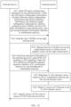
- FIG. 12 is a schematic flowchart of another channel state information feedback method according to an embodiment of this application. As shown in FIG. 12 , the channel state information feedback method includes the following step 1201 to step 1207.
- Anetwork device sends CSI report configuration information to a terminal device, where the CSI report configuration information includes reference signal configuration information and second indication information, the reference signal configuration information is used for configuring four CSI-RSs, the four CSI-RSs correspond to eight antenna ports, and the second indication information indicates K combination matrices.
- a radio frequency unit of the network device includes two digital channels, and analog channels associated with each digital channel are divided into four time-domain non-overlapping subarrays.
- analog channel shutdown patterns There are the following 15 types of analog channel shutdown patterns corresponding to a single digital channel: ⁇ 0001, 0010, 0100, 1000, 0011, 0101, 0110, 1001, 1010, 1100, 0111, 1110, 1111 ⁇ , where 1 indicates that a corresponding subarray is open, and 0 indicates that a corresponding subarray is closed.
- An antenna port 1 to an antenna port 8 respectively correspond to the analog channel subarray 1 to the analog channel subarray 8 in FIG. 11 .
- the eight antenna ports are grouped into four antenna port groups, each antenna port group includes two antenna ports, and each antenna port group corresponds to one CSI-RS. Different antenna port groups correspond to different time domain positions.
- An antenna port group 1 includes the antenna port 1 and the antenna port 5.
- An antenna port group 2 includes the antenna port 2 and the antenna port 6.
- An antenna port group 3 includes the antenna port 3 and the antenna port 7.
- An antenna port group 4 includes the antenna port 4 and the antenna port 8.
- the reference signal configuration information may alternatively be used for configuring only one CSI-RS, which corresponds to eight antenna ports.
- the reference signal configuration information is used for configuring four CSI-RSs is used for description.
- Case 1 Assuming that combination manners of digital ports are the same, there are 15 sets of combination matrices, which respectively correspond to the foregoing analog channel shutdown patterns.
- K is selected from the sets of combination matrices.
- the K combination matrices are all of combination matrices, or the K combination matrices are some of the 15 combination matrices, for example, a combination matrix corresponding to ⁇ 0001, 0010, 0011, 1100, 0111, 1110, 1111 ⁇ .
- the network device sends the four CSI-RSs on the eight antenna ports.
- the terminal device measures the four reference signals sent on the eight antenna ports, to obtain second channel vectors on the eight antenna ports.
- the network device sends first indication information to the terminal device by using MAC-CE signaling or DCI signaling, where the first indication information indicates sequence numbers of K 1 combination matrices in a set including the K combination matrices.
- K 1 may be equal to K , or K 1 may be less than K.
- the terminal device determines K 1 first channel vectors based on the K 1 combination matrices and the second channel vector.
- the network device may not send the first indication information, and the terminal device selects the K 1 combination matrices from the K combination matrices to calculate and report CSI.
- the network device sends the first indication information is used for description.
- K 1 is 2.
- a 1 indicates that the antenna port 1 and the antenna port 3 are combined into an antenna port A, and the antenna port 5 and the antenna port 7 are combined into an antenna port B.
- the network device sends data through the two combined antenna ports. Therefore, the terminal device needs to measure CSI of the two combined antenna ports.
- the terminal device needs to measure CSI of the two combined antenna ports.
- the terminal device needs to measure CSI of the two combined antenna ports.
- the 1 st analog channel subarray and the 3 rd analog channel subarray are reserved for each digital channel, and other analog channel subarrays are closed.
- a 2 indicates that the 1 st antenna port, the 2 nd antenna port, and the 3 rd antenna port are combined into one antenna port, and the 5 th antenna port, the 6 th antenna port, and the 7 th antenna port are combined into one antenna port.
- the network device sends data through the two combined antenna ports. Therefore, the terminal device needs to measure CSI of the two combined antenna ports.
- the terminal device needs to measure CSI of the two combined antenna ports.
- the terminal device needs to measure CSI of the two combined antenna ports.
- the 1 st analog channel subarray, the 2 nd analog channel subarray, and the 3 rd analog channel subarray are reserved for each digital channel, and the 4 th analog channel subarra
- the terminal device obtains K 1 pieces of CSI based on the K 1 first channel vectors.
- the terminal device sends K 2 pieces of CSI in the K 1 pieces of CSI to the network device, where K 2 is a positive integer less than or equal to K 1 .
- the network device may receive the K 2 pieces of channel state information CSI in the K 1 pieces of CSI from the terminal device.
- K 2 K 1 .
- K 2 pieces of CSI there are the following several cases.
- Example 2 Dynamic channel shutdown at a granularity of a digital channel in a full aperture architecture
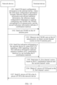
- FIG. 13 is a schematic flowchart of still another channel state information feedback method according to an embodiment of this application. As shown in FIG. 13 , the channel state information feedback method includes the following step 1301 to step 1307.
- a network device sends CSI report configuration information to a terminal device, where the CSI report configuration information includes reference signal configuration information and second indication information, the reference signal configuration information is used for configuring one CSI-RS, the CSI-RS corresponds to 64 antenna ports, and the second indication information indicates K combination matrices.
- the reference signal configuration information may alternatively be used for configuring a plurality of CSI-RSs.
- an example in which the reference signal configuration information is used for configuring one CSI-RS is used.
- Each digital channel is in one-to-one correspondence with an antenna port.
- the network device sends one CSI-RS on the 64 antenna ports.
- the terminal device measures one reference signal sent on the 64 antenna ports, to obtain second channel vectors on the 64 antenna ports.
- the network device sends first indication information to the terminal device by using MAC-CE signaling or DCI signaling, where the first indication information indicates sequence numbers of K 1 combination matrices in a set including the K combination matrices.
- the terminal device determines K 1 first channel vectors based on the K 1 combination matrices and the second channel vector.
- the terminal device determines four first channel vectors based on a combination matrix 1 to a combination matrix 4 and the second channel vector.
- the combination matrix 1 corresponds to the mode 1 of digital channel shutdown and antenna switching shown in FIG. 4 .
- the combination matrix 2 corresponds to the mode 2 of digital channel shutdown and antenna switching shown in FIG. 5 .
- the combination matrix 3 corresponds to the mode 3 of digital channel shutdown and antenna switching shown in FIG. 6 .
- the combination matrix 4 corresponds to the mode 4 of digital channel shutdown and antenna switching shown in FIG. 7 .
- the terminal device can determine, based on the four first channel vectors, CSI in the four modes of digital channel shutdown and antenna switching.
- Each combination matrix in the K combination matrices is divided into eight submatrices.
- Each submatrix is responsible for performing channel shutdown and antenna combination on a subarray including four adjacent channels in a V dimension and two adjacent channels in an H dimension. Eight subarrays in charge of the eight submatrices do not overlap, and correspond to 64 digital channels in total.
- An antenna port 1 to an antenna port 8 respectively correspond to the digital channel 1 to the digital channel 8 in FIG. 4 .
- the submatrix A 1 i indicates that the antenna port 1 and the antenna port 3 are combined into one antenna port, the antenna port 2 and the antenna port 4 are combined into one antenna port, the antenna port 5 and the antenna port 7 are combined into one antenna port, and the antenna port 6 and the antenna port 8 are combined into one antenna port.
- An antenna port 1 to an antenna port 8 respectively correspond to the digital channel 1 to the digital channel 8 in FIG. 5 .
- the submatrix A 2 i indicates that the antenna port 1, the antenna port 3, the antenna port 5, and the antenna port 7 are combined into one antenna port, and the antenna port 2, the antenna port 4, the antenna port 6, and the antenna port 8 are combined into one antenna port.
- An antenna port 1 to an antenna port 8 respectively correspond to the digital channel 1 to the digital channel 8 in FIG. 6 .
- the submatrix A 3 i indicates that the antenna port 1 to the antenna port 4 are combined into one antenna port, and the antenna port 5 to the antenna port 8 are combined into one antenna port.
- An antenna port 1 to an antenna port 8 respectively correspond to the digital channel 1 to the digital channel 8 in FIG. 7 .
- the submatrix A 4 i indicates that the antenna port 1 to the antenna port 8 are combined into one antenna port.
- the terminal device obtains K 1 pieces of CSI based on the K 1 first channel vectors.
- the terminal device sends K 2 pieces of CSI in the K 1 pieces of CSI to the network device, where K 2 is a positive integer less than or equal to K 1 .
- the network device may receive the K 2 pieces of channel state information CSI in the K 1 pieces of CSI from the terminal device.
- the network device and the terminal device include corresponding hardware structures and/or software modules for performing the functions.
- a person skilled in the art should be easily aware that, in combination with the units and the method steps in the examples described in embodiments disclosed in this application, this application can be implemented by using hardware or a combination of the hardware and computer software. Whether a function is performed by hardware or hardware driven by computer software depends on particular application scenarios and design constraints of the technical solutions.
- FIG. 14 and FIG. 15 are schematic diagrams of structures of possible communication apparatuses according to embodiments of this application.
- the communication apparatuses may be configured to implement a function of the terminal device or the network device in the foregoing method embodiments. Therefore, beneficial effects of the foregoing method embodiments can also be implemented.
- the communication apparatus may be any one of the terminal devices 120a to 120j shown in FIG. 8 , may be the network device 110a or 110b shown in FIG. 8 , or may be a module (for example, a chip) used in the terminal device or the network device.
- the communication apparatus 1400 includes a processing unit 1410 and a transceiver unit 1420.
- the communication apparatus 1400 is configured to implement the function of the terminal device or the network device in the method embodiment shown in FIG. 9 .
- the transceiver unit 1420 is configured to receive reference signal configuration information from the network device, where the reference signal configuration information is used for configuring N 1 reference signals, N 1 is a positive integer, the N 1 reference signals correspond to N antenna ports, and N is an integer greater than 1; the processing unit 1410 is configured to: determine K 1 first channel vectors based on K 1 combination matrices and measurement results of the N 1 reference signals on the N antenna ports, and obtain K 1 pieces of channel state information CSI based on the K 1 first channel vectors; and the transceiver unit 1420 is further configured to send K 2 pieces of CSI in the K 1 pieces of CSI to the network device.
- the reference signal configuration information is used for configuring N 1 reference signals
- N 1 is a positive integer
- the N 1 reference signals correspond to N antenna ports
- N is an integer greater than 1
- the processing unit 1410 is configured to: determine K 1 first channel vectors based on K 1 combination matrices and measurement results of the N 1 reference signals on the N antenna ports, and obtain K 1
- the transceiver unit 1420 is configured to: send reference signal configuration information to the terminal device, where the reference signal configuration information is used for configuring N 1 reference signals, and the N 1 reference signals correspond to N antenna ports; send the N 1 reference signals on the N antenna ports; and receive K 2 pieces of channel state information CSI in K 1 pieces of CSI from the terminal device; and the processing unit 1410 is configured to process data.
- processing unit 1410 and the transceiver unit 1420 directly refer to the related descriptions of the method embodiment shown in FIG. 9 . Details are not described herein again.
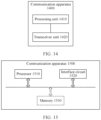
- the communication apparatus 1500 includes a processor 1510 and an interface circuit 1520.
- the processor 1510 and the interface circuit 1520 are coupled to each other.
- the interface circuit 1520 may be a transceiver or an input/output interface.
- the communication apparatus 1500 may further include a memory 1530, configured to: store instructions executed by the processor 1510, or store input data required by the processor 1510 to run the instructions, or store data generated after the processor 1510 runs the instructions.
- the processor 1510 is configured to implement the function of the processing unit 1410
- the interface circuit 1520 is configured to implement the function of the transceiver unit 1420.
- the chip in the terminal device implements the function of the terminal device in the foregoing method embodiments.
- the chip in the terminal device receives information from another module (for example, a radio frequency module or an antenna) in the terminal device, where the information is sent by the network device to the terminal device.
- the chip in the terminal device sends information to another module (for example, a radio frequency module or an antenna) in the terminal device, where the information is sent by the terminal device to the network device.
- the module in the network device implements the function of the network device in the foregoing method embodiments.
- the module in the network device receives information from another module (for example, a radio frequency module or an antenna) in the network device, where the information is sent by the terminal device to the network device.
- the module in the network device sends information to another module (for example, a radio frequency module or an antenna) in the network device, where the information is sent by the network device to the terminal device.
- the module in the network device herein may be a baseband chip of the network device, or may be a DU or another module.
- the DU herein may be a DU in an open radio access network (open radio access network, O-RAN) architecture.
- the processor in this embodiment of this application may be a central processing unit (Central Processing Unit, CPU), or may be another general-purpose processor, a digital signal processor (Digital Signal Processor, DSP), an application-specific integrated circuit (Application-Specific Integrated Circuit, ASIC), a field programmable gate array (Field Programmable Gate Array, FPGA) or another programmable logic device, a transistor logic device, a hardware component, or any combination thereof.
- the general-purpose processor may be a microprocessor or any regular processor.
- the method steps in embodiments of this application may be implemented in a hardware manner, or may be implemented in a manner of executing software instructions by the processor.
- the software instructions may include a corresponding software module.
- the software module may be stored in a random access memory, a flash memory, a read-only memory, a programmable read-only memory, an erasable programmable read-only memory, an electrically erasable programmable read-only memory, a register, a hard disk, a removable hard disk, a CD-ROM, or any other form of storage medium well-known in the art.
- a storage medium is coupled to a processor, so that the processor can read information from the storage medium and write information into the storage medium.
- the storage medium may be a component of the processor.
- the processor and the storage medium may be located in the ASIC.
- the ASIC may be located in the network device or the terminal device. It is clear that the processor and the storage medium may alternatively exist in the network device or the terminal device as discrete components.
- All or some of the foregoing embodiments may be implemented by software, hardware, firmware, or any combination thereof.
- the software is used to implement embodiments, all or some of embodiments may be implemented in a form of a computer program product.
- the computer program product includes one or more computer programs or instructions. When the computer programs or instructions are loaded and executed on a computer, all or some of the procedures or functions in embodiments of this application are executed.
- the computer may be a general-purpose computer, a dedicated computer, a computer network, a network device, user equipment, or another programmable apparatus.
- the computer programs or instructions may be stored in a computer-readable storage medium, or may be transmitted from a computer-readable storage medium to another computer-readable storage medium.
- the computer programs or instructions may be transmitted from a website, computer, server, or data center to another website, computer, server, or data center in a wired manner or in a wireless manner.
- the computer-readable storage medium may be any usable medium that can be accessed by a computer, or a data storage device, such as a server or a data center, integrating one or more usable media.
- the usable medium may be a magnetic medium, for example, a floppy disk, a hard disk, or a magnetic tape; or may be an optical medium, for example, a digital video disc; or may be a semiconductor medium, for example, a solid-state drive.
- the computer-readable storage medium may be a volatile or nonvolatile storage medium, or may include two types of storage media: the volatile storage medium and the non-volatile storage medium.
Landscapes
- Engineering & Computer Science (AREA)
- Signal Processing (AREA)
- Computer Networks & Wireless Communication (AREA)
- Mobile Radio Communication Systems (AREA)
Applications Claiming Priority (2)
| Application Number | Priority Date | Filing Date | Title |
|---|---|---|---|
| CN202110877183.5A CN115694758A (zh) | 2021-07-31 | 2021-07-31 | 一种信道状态信息反馈方法及通信装置 |
| PCT/CN2022/103861 WO2023011088A1 (zh) | 2021-07-31 | 2022-07-05 | 一种信道状态信息反馈方法及通信装置 |
Publications (2)
| Publication Number | Publication Date |
|---|---|
| EP4366186A1 true EP4366186A1 (de) | 2024-05-08 |
| EP4366186A4 EP4366186A4 (de) | 2024-11-06 |
Family
ID=85059627
Family Applications (1)
| Application Number | Title | Priority Date | Filing Date |
|---|---|---|---|
| EP22851803.1A Pending EP4366186A4 (de) | 2021-07-31 | 2022-07-05 | Verfahren zur rückkopplung von kanalstatusinformationen und kommunikationsvorrichtung |
Country Status (4)
| Country | Link |
|---|---|
| US (1) | US20240172025A1 (de) |
| EP (1) | EP4366186A4 (de) |
| CN (1) | CN115694758A (de) |
| WO (1) | WO2023011088A1 (de) |
Families Citing this family (12)
| Publication number | Priority date | Publication date | Assignee | Title |
|---|---|---|---|---|
| CN115484636A (zh) * | 2021-05-31 | 2022-12-16 | 华为技术有限公司 | 信道状态信息的测量方法和装置 |
| CN118524404A (zh) * | 2023-02-17 | 2024-08-20 | 大唐移动通信设备有限公司 | 信息传输方法、装置、终端及网络设备 |
| EP4710669A1 (de) * | 2023-06-09 | 2026-03-18 | Huawei Technologies Co., Ltd. | Verfahren und vorrichtung zur kommunikation |
| CN119652370A (zh) * | 2023-09-18 | 2025-03-18 | 华为技术有限公司 | 一种通信方法及设备 |
| CN121942159A (zh) * | 2023-09-20 | 2026-04-28 | Oppo广东移动通信有限公司 | 信道状态信息的获取方法、装置、设备及介质 |
| CN119728347A (zh) * | 2023-09-28 | 2025-03-28 | 华为技术有限公司 | 通信方法、装置、系统、芯片、芯片模组及存储介质 |
| CN120128966A (zh) * | 2023-12-08 | 2025-06-10 | 华为技术有限公司 | 通信方法及相关装置 |
| CN121013111A (zh) * | 2024-05-24 | 2025-11-25 | 北京三星通信技术研究有限公司 | 通信设备及其执行的方法以及存储介质 |
| CN121240230A (zh) * | 2024-06-28 | 2025-12-30 | 华为技术有限公司 | 通信方法和通信装置 |
| CN121441354A (zh) * | 2024-07-22 | 2026-01-30 | 北京紫光展锐通信技术有限公司 | 通信方法及装置、计算机可读存储介质、计算机程序产品 |
| CN121727600A (zh) * | 2024-09-23 | 2026-03-24 | 华为技术有限公司 | 通信方法和通信装置 |
| CN121908315A (zh) * | 2024-10-14 | 2026-04-21 | 中兴通讯股份有限公司 | 信号测量配置方法、反馈方法以及测量配置和反馈系统 |
Family Cites Families (28)
| Publication number | Priority date | Publication date | Assignee | Title |
|---|---|---|---|---|
| WO2013070577A1 (en) * | 2011-11-07 | 2013-05-16 | Motorola Mobility Llc | Method and apparatus for csi feedback for joint processing schemes in an orthogonal frequency division multiplexing communication system with coordinated multi-point transmission |
| US9059753B2 (en) * | 2012-09-27 | 2015-06-16 | Nokia Solutions & Networks Oy | Non-codebook based channel state information feedback |
| US9438451B2 (en) * | 2013-09-27 | 2016-09-06 | Intel Corporation | CSI-RS antenna ports extension and 3D codebook design |
| WO2015060680A2 (ko) * | 2013-10-24 | 2015-04-30 | 엘지전자 주식회사 | 무선 통신 시스템에서 채널 상태 정보를 보고하는 방법 및 이를 위한 장치 |
| EP3086482B1 (de) * | 2013-12-19 | 2019-08-07 | LG Electronics Inc. | Verfahren zur unterstützung einer referenzsignalübertragung in einem drahtloskommunikationssystem mit mehreren antennen und vorrichtung dafür |
| HUE049819T2 (hu) * | 2014-05-22 | 2020-10-28 | Qualcomm Inc | Periodikus és aperiodikus csatornaállapot információ (CSI) jelentés MIMO-hoz |
| WO2016076657A1 (ko) * | 2014-11-13 | 2016-05-19 | 엘지전자 주식회사 | 다중 안테나 무선 통신 시스템에서 참조 신호 송신 방법 및 이를 위한 장치 |
| US10020860B2 (en) * | 2014-12-02 | 2018-07-10 | Samsung Electronics Co., Ltd. | Downlink signaling for partially precoded CSI-RS and CSI feedback |
| US10110286B2 (en) * | 2015-03-30 | 2018-10-23 | Samsung Electronics Co., Ltd. | Method and apparatus for codebook design and signaling |
| CN106160934B (zh) * | 2015-04-10 | 2019-08-02 | 中国移动通信集团公司 | 一种csi反馈方法、装置和相关设备 |
| CN106301507B (zh) * | 2015-05-18 | 2019-09-13 | 工业和信息化部电信传输研究所 | 一种信道状态信息测量反馈方法 |
| US10536206B2 (en) * | 2015-12-17 | 2020-01-14 | Lg Electronics Inc. | Method for transmitting and receiving channel state information in wireless communication system and apparatus therefor |
| US10651901B2 (en) * | 2016-01-12 | 2020-05-12 | Lg Electronics Inc. | Method for transmitting and receiving channel state information in multi-antenna wireless communication system, and apparatus therefor |
| CN111585627B (zh) * | 2016-06-22 | 2024-10-18 | 上海朗帛通信技术有限公司 | 一种无线通信中的方法和装置 |
| JP6776679B2 (ja) * | 2016-07-15 | 2020-10-28 | セイコーエプソン株式会社 | 無線通信装置、印刷装置、及び、制御方法 |
| CN109644363B (zh) * | 2016-08-29 | 2020-11-06 | 华为技术有限公司 | 信道质量的测量和反馈方法和装置 |
| KR102512849B1 (ko) * | 2016-09-29 | 2023-03-24 | 삼성전자 주식회사 | 측정을 수행하기 위한 장치 및 방법 |
| CN107888265B (zh) * | 2016-09-30 | 2019-08-23 | 中兴通讯股份有限公司 | 信道信息的反馈方法及装置、终端、基站 |
| CN108418662B (zh) * | 2017-02-10 | 2020-04-03 | 华为技术有限公司 | 一种参考信号的发送方法、接收方法及相关设备 |
| AU2018285662B2 (en) * | 2017-06-16 | 2020-11-05 | Telefonaktiebolaget Lm Ericsson (Publ) | Channel state information for reference signals in a wireless communication system |
| US11539417B2 (en) * | 2018-07-30 | 2022-12-27 | Lg Electronics Inc. | Method for transmitting/receiving channel state information in wireless communication system, and device therefor |
| CN110875766B (zh) * | 2018-08-29 | 2021-05-25 | 电信科学技术研究院有限公司 | 信道状态信息反馈方法、预编码矩阵确定方法及装置 |
| KR102607030B1 (ko) * | 2018-09-11 | 2023-11-29 | 프라운 호퍼 게젤샤프트 쭈르 푀르데룽 데어 안겐반텐 포르슝 에. 베. | 무선 통신 시스템을 위한 도플러 코드북-기반 프리코딩 및 csi 보고 |
| WO2021148629A1 (en) * | 2020-01-24 | 2021-07-29 | Fraunhofer-Gesellschaft zur Förderung der angewandten Forschung e.V. | Csi reporting based on linear combination port-selection codebook |
| EP4046440A4 (de) * | 2020-02-12 | 2022-11-02 | Apple Inc. | Typ-ii-csi-portauswahl-codebucherweiterung mit partieller reziprozität |
| WO2021093204A1 (en) * | 2020-02-13 | 2021-05-20 | Zte Corporation | Acquiring channel state information |
| US20230283341A1 (en) * | 2020-08-07 | 2023-09-07 | Nokia Technologies Oy | CSI Triggering and Configuration Enhancements for Partial-Reciprocity Based Port Selection Codebook |
| WO2022077430A1 (en) * | 2020-10-16 | 2022-04-21 | Qualcomm Incorporated | Resource selection for single and multiple transmit/receive points (trp) channel state information (csi) reporting |
-
2021
- 2021-07-31 CN CN202110877183.5A patent/CN115694758A/zh active Pending
-
2022
- 2022-07-05 WO PCT/CN2022/103861 patent/WO2023011088A1/zh not_active Ceased
- 2022-07-05 EP EP22851803.1A patent/EP4366186A4/de active Pending
-
2024
- 2024-01-30 US US18/426,785 patent/US20240172025A1/en active Pending
Also Published As
| Publication number | Publication date |
|---|---|
| CN115694758A (zh) | 2023-02-03 |
| WO2023011088A1 (zh) | 2023-02-09 |
| US20240172025A1 (en) | 2024-05-23 |
| EP4366186A4 (de) | 2024-11-06 |
Similar Documents
| Publication | Publication Date | Title |
|---|---|---|
| EP4366186A1 (de) | Verfahren zur rückkopplung von kanalstatusinformationen und kommunikationsvorrichtung | |
| US11962535B2 (en) | Method and apparatus for configuring reference signal channel characteristics, and communication device | |
| US11283503B2 (en) | Communication method and communications apparatus | |
| RU2726850C2 (ru) | Система и способ передачи информации о выборе подпространства | |
| EP4210378B1 (de) | Verfahren und vorrichtung zur meldung von kanalstatusinformationen | |
| US11012129B2 (en) | Transmission of reference signals from a terminal device | |
| CN110475355A (zh) | 一种波束训练的方法、装置及系统 | |
| CN105684321A (zh) | 无线通信系统中发送和接收波束信息的装置及方法 | |
| US20250374107A1 (en) | Dynamic adaptation of spatial elements | |
| WO2018028544A1 (zh) | 导频配置和信息反馈方法、装置及系统 | |
| CN115379470B (zh) | 波束成形方法及相关装置 | |
| CN116528283A (zh) | 一种通信方法、装置及系统 | |
| CN120881771A (zh) | 一种通信方法及装置 | |
| CN119921821A (zh) | 一种通信方法及装置 | |
| WO2026032163A9 (zh) | 一种通信方法和装置 | |
| WO2025228170A9 (zh) | 一种通信方法及装置 | |
| WO2026021262A1 (zh) | 一种用于测量的通信方法及装置 | |
| WO2026046128A1 (zh) | 一种通信方法及装置 | |
| CN120320807A (zh) | 一种通信方法、装置以及存储介质 | |
| WO2025086992A1 (zh) | 一种通信方法、装置、存储介质及计算机程序产品 | |
| WO2025232858A1 (zh) | 一种通信方法及装置 | |
| KR20240098546A (ko) | 무선 통신 시스템에서 채널 상태 정보 (channel state information, CSI) 보고 (report)를 위한 보고 설정(report configuration) 및 자원 설정 (resource configuration)을 수행하는 방법 및 장치 | |
| WO2024235097A1 (zh) | 一种通信方法及装置 | |
| CN121510269A (zh) | 一种通信方法及装置 | |
| CN121909708A (zh) | 与无线通信有关的方法和装置 |
Legal Events
| Date | Code | Title | Description |
|---|---|---|---|
| STAA | Information on the status of an ep patent application or granted ep patent |
Free format text: STATUS: THE INTERNATIONAL PUBLICATION HAS BEEN MADE |
|
| PUAI | Public reference made under article 153(3) epc to a published international application that has entered the european phase |
Free format text: ORIGINAL CODE: 0009012 |
|
| STAA | Information on the status of an ep patent application or granted ep patent |
Free format text: STATUS: REQUEST FOR EXAMINATION WAS MADE |
|
| 17P | Request for examination filed |
Effective date: 20240201 |
|
| AK | Designated contracting states |
Kind code of ref document: A1 Designated state(s): AL AT BE BG CH CY CZ DE DK EE ES FI FR GB GR HR HU IE IS IT LI LT LU LV MC MK MT NL NO PL PT RO RS SE SI SK SM TR |
|
| A4 | Supplementary search report drawn up and despatched |
Effective date: 20241004 |
|
| DAV | Request for validation of the european patent (deleted) | ||
| DAX | Request for extension of the european patent (deleted) | ||
| RIC1 | Information provided on ipc code assigned before grant |
Ipc: H04W 24/10 20090101ALI20240927BHEP Ipc: H04L 5/00 20060101ALI20240927BHEP Ipc: H04L 1/06 20060101ALI20240927BHEP Ipc: H04B 7/0456 20170101ALI20240927BHEP Ipc: H04B 7/06 20060101AFI20240927BHEP |