EP4366579B1 - Dispositif de séparation et machine de fabrication de brosses dotée d'un dispositif de séparation - Google Patents
Dispositif de séparation et machine de fabrication de brosses dotée d'un dispositif de séparation Download PDFInfo
- Publication number
- EP4366579B1 EP4366579B1 EP22719276.2A EP22719276A EP4366579B1 EP 4366579 B1 EP4366579 B1 EP 4366579B1 EP 22719276 A EP22719276 A EP 22719276A EP 4366579 B1 EP4366579 B1 EP 4366579B1
- Authority
- EP
- European Patent Office
- Prior art keywords
- picking
- adjusting
- notches
- disk
- notch
- Prior art date
- Legal status (The legal status is an assumption and is not a legal conclusion. Google has not performed a legal analysis and makes no representation as to the accuracy of the status listed.)
- Active
Links
Images


Classifications
-
- A—HUMAN NECESSITIES
- A46—BRUSHWARE
- A46D—MANUFACTURE OF BRUSHES
- A46D1/00—Bristles; Selection of materials for bristles
- A46D1/04—Preparing bristles
-
- A—HUMAN NECESSITIES
- A46—BRUSHWARE
- A46D—MANUFACTURE OF BRUSHES
- A46D3/00—Preparing, i.e. Manufacturing brush bodies
- A46D3/04—Machines for inserting or fixing bristles in bodies
-
- A—HUMAN NECESSITIES
- A46—BRUSHWARE
- A46D—MANUFACTURE OF BRUSHES
- A46D3/00—Preparing, i.e. Manufacturing brush bodies
- A46D3/08—Parts of brush-making machines
- A46D3/082—Magazines for bristles; Feeding bristles to magazines; Knot picking
Definitions
- the invention relates to a separating device for separating bristle bundles from a bristle supply, wherein the separating device comprises a bristle magazine for receiving a bristle supply and a separating disc having at least two separating notches on its circumference and movable with its at least two separating notches past a removal opening of the bristle magazine for separating bristle bundles from a bristle supply located in the bristle magazine. Furthermore, the invention also relates to a brush manufacturing machine having at least one such separating device.
- Partition devices of the type mentioned above are known from practice and the state of the art, for example from the publications DE 20 2004 016 409 U1 and DE 40 40 297 A1 , in various embodiments, are already known. They are used to separate bristle bundles from a supply of loose bristle filaments and to prepare them for further processing in the production of brushes, especially toothbrushes.
- the so-called effective notch volume of the at least two dividing notches of the dividing disc of the dividing device determines the number of individual bristle filaments that can be separated from the supply of loose bristle filaments in each bristle bundle using the dividing notches.
- the number of individual bristle filaments in a bundle of bristles, whether separated or taken from the bristle stock, has a more or less large tolerance range.
- a large tolerance range can, for example, stipulate that a bundle of bristles A bristle bundle meets the requirements if it comprises 20 +/- 5 bristle filaments.
- a small tolerance range may stipulate that the bristle bundle can only be classified as satisfactory if the bristle bundle comprises 20 +/- 1 individual bristle filaments.
- a partitioning device of the type mentioned above which has the means and features of the independent claim directed to a partitioning device.
- the partitioning device mentioned above comprise an adjustment device configured to adjust an effective notch volume of the at least two partitioning notches available for partitioning bristle bundles.
- the effective notch volume can be the volume of the compartmentalizing notches that is available when dividing bristle bundles from a supply of loose bristle filaments and ultimately also determines the number of bristle filaments that can be accommodated in the compartmentalizing notches during compartmentalization.
- the adjustment device it is possible to adjust the effective notch volume of the sectioning notches of the sectioning disc depending on the number of bristle filaments actually contained in a sectioned bristle bundle. If it is determined that the sectioned bristle bundles contain too few bristle filaments, the effective notch volume of the sectioning notches can be adjusted accordingly, in particular increased, using the adjustment device. Likewise, in the opposite case, i.e., if a bristle bundle sectioned using the sectioning notches contains too many individual bristle filaments, the effective notch volume of the sectioning notches can be reduced using the adjustment device.
- the adjustment device of the inventive sectioning device thus makes it possible to influence the number of individual bristle filaments in separated bristle bundles by changing the effective notch volume of the sectioning notches of the sectioning disc. In this way, a new sectioning disc that meets the specifications regarding the number of cut bristle filaments per separated bristle bundle is not met.
- the adjustment device for adjusting the effective notch volume of the at least two compartmentalizing notches comprises at least one adjustment means movable relative to the compartmentalizing notches.
- the adjustment means can be moved relative to the compartmentalizing notches in such a way that the effective usable notch volume of the compartmentalizing notches can be changed as desired by the relative position of the adjustment means to the at least two compartmentalizing notches.
- the adjusting means can be rotatably mounted on the dividing disc and can have an eccentric cam.
- the eccentric cam can be guided in an elongated hole in the adjusting disc, preferably aligned radially with the adjusting disc. Using the eccentric cam and the elongated hole, a rotary movement of the adjusting means can be converted into a relative rotary movement between the dividing disc and the adjusting disc, thereby adjusting the effective notch volume of the dividing notches.
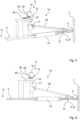
- the Figures 1-14 show at least parts of a whole designated 1, which is designed to separate bristle bundles 2 from a bristle supply 3.
- the separating device 1 has a bristle magazine 4 for receiving a bristle supply 3 of loose bristle filaments and a separating disc 5.
- the separating disc 5 has a plurality of separating notches 6 on its circumference, a total of nine separating notches 6 in the embodiment shown in the figures.
- the separating disc 5, with its total of nine separating notches 6, can be moved past a removal opening 7 of the bristle magazine 4 for separating bristle bundles 7 from the bristle supply 3 located in the bristle magazine 4.
- the dividing device 1 has an adjusting device 8 which is designed to adjust an effective notch volume of the dividing notches 6 available for dividing bristle bundles 2.
- the adjusting device 8 has at least one adjusting means 9 which is movable relative to at least one of the compartment notches 6 in order to adjust the effective notch volume of the compartment notches 6.
- the adjusting device 8 for adjusting the effective notch volumes of the total of nine compartmentalizing notches 6 has an adjusting means 9 in the form of a slider 10 which is movable relative to the respective compartmentalizing notch 6.
- the sliders 10 can be moved relative to the respective compartment notches 6.
- the respective slider can be inserted radially outward into the respective compartment notch 6, starting from a center point 11 of the compartment disc 5.
- the dividing disc 5 has a sliding guide 12 for each slider 10, which according to the sectional view of the dividing disc 5 of the Figure 6 is formed within the compartment disc 5.
- the adjustment device 8 of the Figures 1-6 The dividing device 1 shown has a return means 13 in the form of a tension spring for each slide 10. Against the return force of the respective return means 13, which is directed in the radial direction towards the center 11 of the dividing disc 5, the slides 10 can be used to adjust, in particular to reduce, the effective notch volume the respective dividing notch 6 can be displaced relative to it.
- the return means 13 serve to keep the respective slides 10 positioned without play, whereby the respectively set effective notch volume of the respective dividing notch 6 can be kept constant, even when the dividing disc 5 is moved to divide bristle bundles 2.
- the adjustment means 9 shown are continuously movable for continuously adjusting the effective notch volume of the compartment notches 6.
- the adjustment device 8 has a displacement mechanism 14 which is designed to displace the respective adjustment means 9, in particular when it is designed as a slider 10, relative to the individual compartment notches 6.
- the displacement mechanism 14 comprises a spindle drive 15.
- the spindle drive 15 comprises a rotatable spindle 16, which is designed as a threaded spindle, and a spindle nut 17.
- the spindle nut 17 is connected via a lever 18 to the adjusting means 9, here to the respective slide 10, in order to displace the adjusting means 9 by a rotation of the spindle 16 and a resulting axial movement of the spindle nut 17 with respect to the spindle 16 relative to the respective compartmentalizing notch 6.
- the lever 18 is connected in an articulated manner on the one hand to the spindle nut 17 and on the other hand to the adjusting means 9, in particular to the slide 10. In this way, the axial movement of the spindle nut 17 on the rotatable spindle 16 of the spindle drive 15 can be converted into a sliding movement of the adjusting means 9 in order to adjust the effective notch volume of the respective compartment notch 6 as desired. and if necessary even specify 6 individually for each compartment notch.
- the spindle drive 15 comprises an actuator 19 for driving the spindle 16.
- the actuator 19 can be designed as a motor and/or as a manually operable rotary handle and/or as a manually operable handwheel.
- the spindle 16 is designed as a threaded spindle and can have a thread whose pitch is selected depending on the adjustment range of the adjustment means 9.
- spindle 16 It is possible to equip the spindle 16 with a normal thread or with a fine thread, for example.
- the adjustment device 8 further comprises a locking mechanism 20.
- the locking mechanism 20 is configured to lock the respective adjustment means 9 in its set position to prevent the position of the adjustment means 9 from changing during a movement of the dividing disc 5.
- the locking mechanism 20 shown in the figures is configured to lock a respectively set rotational position of the respective spindle 16 of the spindle drives 15.
- the locking mechanism 20 comprises pawls 40, which prevent the spindle 16 from continuing to rotate unintentionally.
- Each adjustment means 9 shown is assigned its own locking mechanism 20. This is advantageous and useful since each adjustment means 9 can be moved individually relative to the respective compartment notch 6 to individually specify the effective notch volume of the individual compartment notches 6.
- the compartment disc 5 has, according to the Figures 1 to 6 material-free areas 38.
- the Figures 7-13 serve to illustrate a further embodiment of an adjusting device 8.
- the adjusting device 8 shown in these figures has an adjusting disc 21 as at least one adjusting means 9.
- the Figures 9-13 which show this adjusting disc 21, illustrate that the adjusting disc 21 has a number of adjusting notches 22, namely nine, which correspond in number, arrangement, geometry and dimensions to the dividing notches 6 of the dividing disc 5.
- the adjusting disc 21 has the same diameter as the dividing disc 5 and, just like the latter, is circular.
- the adjusting disc 21 is rotatable relative to the dividing disc 5, namely around the same axis of rotation, which runs both around the center point 11 of the dividing disc 5 and through the center point 39 of the adjusting disc 21.
- the adjusting device 8 comprises an adjusting means 23, which is designed here as an eccentric and is part of a displacement mechanism 14 of the adjusting device 8 of this embodiment.
- the adjusting means 23 is in Figure 8 shown and rotatably mounted on the dividing disc 5.
- the adjusting means 23 has an eccentric cam 24 which is guided in a slot 25 of the adjusting disc 21 which is aligned in the radial direction on the adjusting disc 21 in order to prevent a rotational movement of the adjusting means 23 into a relative rotational movement of the adjusting disc 21 to the dividing disc 5.
- FIG. 10 shows the compartment notches 6 with their maximum effective notch volume.
- FIGS 1-6 illustrate that the setting device 8 of the compartmentalizing device 1 shown there has a setting indicator 26 for each setting means 9, which is designed to display the respective position of the respective setting means 9 and thereby to display the respectively set effective notch volume of the respective compartmentalizing notch 6.
- compartment disc 5 of the Figures 1-6 The compartment device 1 shown has compartment notches 6 which differ from one another in terms of their size, namely their width, and/or their geometry. This is particularly evident from Figure 2 There you can see that the uppermost compartment notch 6 in the cutout has a greater width than the others in the cutout of the Figure 2 shown compartment notches 6.
- the sectioning device 1 shown further comprises a transport device 27 which is designed to transport the sectioned bristle bundles 2 held ready in the sectioning notches 6 to a downstream processing station 29 of a brush manufacturing machine 28.
- the Transport device 27 is according to Fig. 14 for transporting the bristle bundles 2 to the downstream processing station 29 of the brush manufacturing machine 28 by means of negative pressure.
- the transport device 27 has a total of nine transport lines 30, with the aid of which the bristle bundles 2 can be removed from the compartment notches 6 and transported to the processing station 29 of the brush manufacturing machine 28.
- the processing station 29 can, for example, be a processing station at which the bristle bundles 2 are reworked, for example milled and/or ground and/or connected to carrier plates and/or brush bodies of brushes to be produced.
- the dividing device 1 further comprises a counter-holding device 31 which has a movable counter-holder 32 which is assigned to the dividing disc 5.
- the counterholder 32 can be removed from the Figures 1 and 2 shown, the compartment disc 5 approximated position into the position shown in the Figures 3 and 4 shown, spaced position, in which the compartment notches 6 and bristle bundles 2 positioned therein are released for removal by means of the transport device 27.
- a bundle pusher 33 is assigned to a pusher device 34, by means of which the bristle bundles 2 located in the compartmentalizing notches 6 can be pushed radially outwards from the compartmentalizing notches 6 for removal by means of the transport device 27.
- the separating device 1 further comprises a rotary drive 35, with which the separating disc 5 can be set in rotation in order to separate the bristle bundles 2 from the bristle magazine 4.
- the dividing device 1 In order to guide the separated bristle bundles 2 on their way from the bristle magazine 4 to a transport device 27
- the dividing device 1 In order to secure the bristle bundles 2 in the transfer position located there, the dividing device 1 also has counterparts 36 which take up the outer contour of the dividing disc 5 and are assigned to the dividing disc 5.
- the counterparts 36 each have a circular arc-shaped contour on their flanks assigned to the dividing disc 5, which serve to secure the bristle bundles 2 in the dividing notches during a movement of the dividing disc relative to the counterparts 36.
- the dividing device 1 In order to be able to press the bristle supply 3 located in the bristle magazine 4 against the dividing disc 5, the dividing device 1 has a corresponding material pusher 37, with which the bristle supply 3 arranged in the bristle magazine 4 can be subjected to appropriate pressure. This promotes the reliable and uniform removal of bristle bundles 2 from the bristle supply 3 of the bristle magazine 4 with the aid of the dividing disc 5.
Landscapes
- Engineering & Computer Science (AREA)
- Manufacturing & Machinery (AREA)
- Brushes (AREA)
- Packaging Of Annular Or Rod-Shaped Articles, Wearing Apparel, Cassettes, Or The Like (AREA)
- Transmission Devices (AREA)
Claims (15)
- Dispositif de segmentation (1) pour la segmentation de faisceaux de poils de brosse (2) à partir d'une réserve de poils de brosse (3), lequel dispositif de segmentation (1) comporte un magasin de poils de brosse (4) destiné à recevoir une réserve de poils de brosse (3) et un disque de segmentation (5), caractérisé en ce que le disque de segmentation (5) comporte sur sa circonférence au moins deux encoches de segmentation (6) et peut, pour segmenter des faisceaux de poils de brosse (2) à partir d'une réserve de poils de brosse (3) qui se trouve dans le magasin de poils de brosse (4), être déplacé pour faire passer ses encoches de segmentation (6) devant une ouverture de prélèvement (7) du magasin de poils de brosse (4), le dispositif de segmentation (1) comprenant un dispositif de réglage (8) configuré pour régler un volume d'encoche effectif des encoches de segmentation (6) disponible pour segmenter des faisceaux de poils de brosse (2).
- Dispositif de segmentation (1) selon la revendication précédente, dans lequel le dispositif de réglage (8) pour le réglage du volume d'encoche effectif des encoches de segmentation (6) comporte au moins un moyen de réglage (9) mobile vis-à-vis d'au moins une des au moins deux encoches de segmentation (6).
- Dispositif de segmentation (1) selon l'une des revendications précédentes, dans lequel le dispositif de réglage (8) présente, pour chaque encoche de segmentation (6), un moyen de réglage (9) mobile vis-à-vis de l'encoche de segmentation (6) en question, en particulier un poussoir (10), pour le réglage, de préférence individuel, du volume effectif d'encoche de l'encoche de segmentation (6) en question.
- Dispositif de segmentation (1) selon l'une des revendications 2 ou 3, dans lequel l'au moins un moyen de réglage (9) est un poussoir (10) qui peut être déplacé vis-à-vis d'au moins une des encoches de segmentation (6) pour régler le volume effectif d' encoche d'au moins une encoche de segmentation (6), de préférence dans lequel le poussoir (10) est capable de translation dans et/ou sur l'au moins une des encoches de segmentation (6) pour le réglage du volume d'encoche effectif de l'au moins une encoche de segmentation (6), en particulier dans le sens radial vers l'extérieur à partir d'un centre (11) du disque de segmentation (5).
- Dispositif de segmentation (1) selon l'une des revendications 3 ou 4, dans lequel le dispositif de réglage (8) comprend au moins un moyen de rappel (13), par exemple un ressort de traction, ayant une force de rappel orientée en particulier dans le sens radial vers un centre (11) du disque de segmentation (6) contre laquelle l'au moins un poussoir (10) peut être déplacé vis-à-vis des encoches de segmentation (6) pour régler, en particulier pour réduire, le volume effectif d'encoche.
- Dispositif de segmentation (1) selon l'une des revendications 2 à 5, dans lequel le dispositif de réglage (8) comprend au moins un mécanisme de translation (14) qui est configuré de façon à déplacer l'au moins un moyen de réglage (9), en particulier un poussoir (10), vis-à-vis des encoches de segmentation (6), de préférence dans lequel l'au moins un mécanisme de translation (14) comprend un entraînement à broche (15) avec une broche rotative (16) et un écrou de broche (17), lequel écrou de broche (17) est relié par un levier (18) à l'au moins un moyen de réglage (9), en particulier avec l'au moins un poussoir (10), afin de déplacer le moyen de réglage (9) vis-à-vis d'à au moins une des encoches de segmentation (6) par une rotation de la broche (16) et un mouvement de l'écrou de broche (17) dans le sens axial vis-à-vis de la broche provoqué par celle-ci, et/ou dans lequel l'entraînement à broche (15) comporte un actionneur (19) pour l'entraînement de la broche (16), en particulier un moteur et/ou une poignée rotative et/ou un volant manuel.
- Dispositif de segmentation (1) selon l'une des revendications 2 à 6, dans lequel le dispositif de réglage (8) comporte un mécanisme d'arrêt (20) qui est configuré pour arrêter l'au moins un moyen de réglage (9) dans sa position réglée, en particulier dans lequel le mécanisme d'arrêt (20) est configuré pour arrêter une ou la broche (16) d'un ou de l'entraînement à broche (15) dans une position de rotation.
- Dispositif de segmentation (1) selon l'une des revendications 2 à 7, dans lequel le dispositif de réglage (8) comporte comme au moins un moyen de réglage (9) un disque de réglage (21) qui comporte un certain nombre d'encoches de réglage (22), en particulier au moins deux encoches de réglage (22), dont le nombre et/ou la disposition et/ou la géométrie et/ou les dimensions coïncident avec le nombre et/ou la disposition et/ou la géométrie et/ou les dimensions des encoches de segmentation (6) du disque de segmentation (5).
- Dispositif de segmentation (1) selon la revendication précédente, dans lequel le disque de réglage (21) est capable de rotation vis-à-vis du disque de segmentation (5) pour modifier une position relative des encoches de réglage (22) vis-à-vis des encoches de segmentation (6) du disque de segmentation (5) et régler ainsi un volume d'encoche effectif des encoches de segmentation (6).
- Dispositif de segmentation (1) selon l'une des revendications 8 ou 9, dans lequel le dispositif de réglage (8) destiné à modifier une position de rotation relative du disque de segmentation (5) vis-à-vis du disque de réglage (21) est un moyen d'ajustement (23), en particulier un excentrique, en particulier dans lequel le moyen d'ajustement (22) fait partie d'un ou du mécanisme de translation (14).
- Dispositif de segmentation (1) selon la revendication précédente, dans lequel le moyen d'ajustement (23), en particulier l'excentrique, est supporté avec possibilité de rotation sur le disque de segmentation (5) et une came d'excentrique (24) du moyen d'ajustement (23) est guidée dans un trou oblong (25) du disque de réglage (21), orienté de préférence dans le sens radial sur le disque de réglage (21), afin de transformer un mouvement de rotation du moyen d'ajustement (23) en mouvement de rotation relatif du disque de réglage (21) vis-à-vis du disque de segmentation (5), et/ou dans lequel l'au moins un moyen de réglage (9) peut se déplacer en continu.
- Dispositif de segmentation (1) selon l'une des revendications précédentes, dans lequel le dispositif de réglage (8) comporte au moins un indicateur d'ajustement (26) qui est configuré pour indiquer une position d'au moins un moyen de réglage (9) et/ou pour indiquer un volume effectif d'encoche réglé pour au moins une encoche de segmentation (6).
- Dispositif de segmentation (1) selon l'une des revendications précédentes, dans lequel le disque de segmentation (5) comporte au moins deux encoches de segmentation (6) de taille différente, en particulier de largeur différente et/ou de géométrie différente.
- Dispositif de segmentation (1) selon l'une des revendications précédentes, avec un dispositif de transport (27) qui est configuré pour transporter des faisceaux de poils de brosse (2) mis à disposition dans les encoches de segmentation (6) vers un poste de traitement (29) d'une machine à fabriquer les brosses (28) situé en aval, en particulier dans lequel le dispositif de transport (27) est configuré pour transporter les faisceaux de poils de brosse (2) au moyen d'une dépression.
- Machine à fabriquer les brosses (28) munie d'au moins un dispositif de segmentation (1) selon l'une des revendications 1 à 14.
Applications Claiming Priority (2)
| Application Number | Priority Date | Filing Date | Title |
|---|---|---|---|
| DE102021117793.6A DE102021117793B4 (de) | 2021-07-09 | 2021-07-09 | Abteilvorrichtung und Bürstenherstellungsmaschine mit einer Abteilvorrichtung |
| PCT/EP2022/058329 WO2023280450A1 (fr) | 2021-07-09 | 2022-03-29 | Dispositif de séparation et machine de fabrication de brosses dotée d'un dispositif de séparation |
Publications (2)
| Publication Number | Publication Date |
|---|---|
| EP4366579A1 EP4366579A1 (fr) | 2024-05-15 |
| EP4366579B1 true EP4366579B1 (fr) | 2025-07-09 |
Family
ID=81388779
Family Applications (1)
| Application Number | Title | Priority Date | Filing Date |
|---|---|---|---|
| EP22719276.2A Active EP4366579B1 (fr) | 2021-07-09 | 2022-03-29 | Dispositif de séparation et machine de fabrication de brosses dotée d'un dispositif de séparation |
Country Status (8)
| Country | Link |
|---|---|
| US (1) | US20240285064A1 (fr) |
| EP (1) | EP4366579B1 (fr) |
| JP (1) | JP2024525467A (fr) |
| KR (1) | KR20240033224A (fr) |
| CN (1) | CN117479864A (fr) |
| DE (1) | DE102021117793B4 (fr) |
| TW (1) | TW202302013A (fr) |
| WO (1) | WO2023280450A1 (fr) |
Citations (6)
| Publication number | Priority date | Publication date | Assignee | Title |
|---|---|---|---|---|
| DE10062398A1 (de) | 2000-01-19 | 2001-07-26 | Schiffer Fa M & C | Verfahren zur Bildung eines Borstenbündels sowie eine zur Durchführung des Verfahrens geeignete Vorrichtung |
| DE202004016409U1 (de) | 2004-10-22 | 2005-02-24 | Firma G.B. Boucherie N.V. | Bündelabnahmevorrichtung für eine Bürstenherstellungsmaschine |
| WO2017174152A1 (fr) | 2016-04-08 | 2017-10-12 | M+C Schiffer Gmbh | Dispositif d'alimentation d'une cassette de filaments de poils en charges de filaments de poils |
| WO2017186322A1 (fr) | 2016-04-25 | 2017-11-02 | Zahoransky Ag | Dispositif de prélèvement de touffes et machine de fabrication de brosses |
| US20190307241A1 (en) | 2017-01-24 | 2019-10-10 | The Procter & Gamble Company | Tuft picker for a brush making machine |
| US20190374020A1 (en) | 2017-01-24 | 2019-12-12 | The Procter & Gamble Company | Tuft picker for a brush making machine |
Family Cites Families (2)
| Publication number | Priority date | Publication date | Assignee | Title |
|---|---|---|---|---|
| DE4040297C2 (de) * | 1990-12-17 | 2003-08-21 | Zahoransky Anton Gmbh & Co | Bürstenherstellungsmaschine |
| BE1023541B1 (de) | 2014-06-05 | 2017-04-28 | Bart Gerard Boucherie | Bürstenstopfvorrichtung |
-
2021
- 2021-07-09 DE DE102021117793.6A patent/DE102021117793B4/de active Active
-
2022
- 2022-03-29 WO PCT/EP2022/058329 patent/WO2023280450A1/fr not_active Ceased
- 2022-03-29 EP EP22719276.2A patent/EP4366579B1/fr active Active
- 2022-03-29 KR KR1020247000297A patent/KR20240033224A/ko active Pending
- 2022-03-29 CN CN202280041135.5A patent/CN117479864A/zh active Pending
- 2022-03-29 US US18/569,662 patent/US20240285064A1/en active Pending
- 2022-03-29 JP JP2023580625A patent/JP2024525467A/ja active Pending
- 2022-05-06 TW TW111117192A patent/TW202302013A/zh unknown
Patent Citations (7)
| Publication number | Priority date | Publication date | Assignee | Title |
|---|---|---|---|---|
| DE10062398A1 (de) | 2000-01-19 | 2001-07-26 | Schiffer Fa M & C | Verfahren zur Bildung eines Borstenbündels sowie eine zur Durchführung des Verfahrens geeignete Vorrichtung |
| DE202004016409U1 (de) | 2004-10-22 | 2005-02-24 | Firma G.B. Boucherie N.V. | Bündelabnahmevorrichtung für eine Bürstenherstellungsmaschine |
| EP1649778A2 (fr) | 2004-10-22 | 2006-04-26 | Firma G.B. BOUCHERIE, naamloze vennootschap | Dispositif pour préparer des touffes pour une machine de fabrication de brosse |
| WO2017174152A1 (fr) | 2016-04-08 | 2017-10-12 | M+C Schiffer Gmbh | Dispositif d'alimentation d'une cassette de filaments de poils en charges de filaments de poils |
| WO2017186322A1 (fr) | 2016-04-25 | 2017-11-02 | Zahoransky Ag | Dispositif de prélèvement de touffes et machine de fabrication de brosses |
| US20190307241A1 (en) | 2017-01-24 | 2019-10-10 | The Procter & Gamble Company | Tuft picker for a brush making machine |
| US20190374020A1 (en) | 2017-01-24 | 2019-12-12 | The Procter & Gamble Company | Tuft picker for a brush making machine |
Also Published As
| Publication number | Publication date |
|---|---|
| JP2024525467A (ja) | 2024-07-12 |
| WO2023280450A1 (fr) | 2023-01-12 |
| CN117479864A (zh) | 2024-01-30 |
| KR20240033224A (ko) | 2024-03-12 |
| DE102021117793A1 (de) | 2023-01-12 |
| DE102021117793B4 (de) | 2024-03-14 |
| EP4366579A1 (fr) | 2024-05-15 |
| US20240285064A1 (en) | 2024-08-29 |
| TW202302013A (zh) | 2023-01-16 |
Similar Documents
| Publication | Publication Date | Title |
|---|---|---|
| EP2243582B1 (fr) | Procédé et dispositif d'élimination d'un appareil secondaire sur une roue de pièce usinée interdigitée à l'avant | |
| EP2629917B1 (fr) | Fraise pour dent et procédé de fraisage des dents d'éléments d'engrenage à dents | |
| DE4447253C2 (de) | Federherstellungsvorrichtung, sowie Drahtführung für eine Federherstellungsvorrichtung | |
| EP2208566B1 (fr) | Outil de coupe avec couteau de coupe par enlèvement et méthode pour attacher le couteau de coupe à l'outil de coupe | |
| EP0108935A2 (fr) | Presse à estamper à poinçon multiple | |
| DE3644854A1 (de) | Werkstueckhalter | |
| DE572376C (de) | Vorrichtung zum Aufwickeln kuenstlicher Faeden | |
| DE19539107A1 (de) | Schleifwerkzeug mit verdralltem Stiel und Verfahren für dessen Herstellung | |
| DE4213911C2 (de) | Hondorn | |
| DE2624599C2 (de) | Rotierender Werkzeughalter mit einem in ihm aufgenommenen Zerspanungswerkzeug | |
| EP4366579B1 (fr) | Dispositif de séparation et machine de fabrication de brosses dotée d'un dispositif de séparation | |
| DE2525872B2 (de) | Entgratwerkzeug zur spanabhebenden Bearbeitung des Öffnungsrandes von Bohrungen | |
| DE2112092A1 (de) | Werkzeughalter | |
| EP0231911A2 (fr) | Procédé pour l'ajustage automatique du guidage d'une barre pour une machine à tourner CNC et machine à tourner pour la mise en oeuvre de ce procédé | |
| EP3401036B1 (fr) | Ensemble d'outils à composants d'outil permettant de configurer des outils de cintrage | |
| EP0717666A1 (fr) | Porte-brosse reglable en continu | |
| DE68904096T2 (de) | Kontrolleinrichtung zum positionieren von zwei oder mehr werkzeugen in einer maschine, speziell einer jalousieherstellungsmaschine. | |
| DE19500515B4 (de) | Werkzeugkopf für Rohrgewindeschneidmaschinen | |
| EP3934837A1 (fr) | Outil de fraisage périphérique et procédé servant à agencer des arêtes tranchantes | |
| EP3986680A1 (fr) | Procédé de fabrication de cisailles et combinaison d'au moins deux cisailles | |
| EP4463037B1 (fr) | Procédé de segmentation de faisceaux de poils, dispositif de segmentation et machine de touffetage de brosse | |
| DE102024108892B3 (de) | Umformwerkzeug, Umformvorrichtung und Verfahren zur Herstellung einer Verzahnung an einem Werkstück | |
| DE1943586A1 (de) | Werkzeug,insbesondere Spiralbohrer,und Verfahren zu seiner Herstellung | |
| EP1045170B1 (fr) | Roue dentée coulissante pour engrenage de changement de vitesse | |
| DE102018113947A1 (de) | Spannfutter |
Legal Events
| Date | Code | Title | Description |
|---|---|---|---|
| STAA | Information on the status of an ep patent application or granted ep patent |
Free format text: STATUS: UNKNOWN |
|
| STAA | Information on the status of an ep patent application or granted ep patent |
Free format text: STATUS: THE INTERNATIONAL PUBLICATION HAS BEEN MADE |
|
| PUAI | Public reference made under article 153(3) epc to a published international application that has entered the european phase |
Free format text: ORIGINAL CODE: 0009012 |
|
| STAA | Information on the status of an ep patent application or granted ep patent |
Free format text: STATUS: REQUEST FOR EXAMINATION WAS MADE |
|
| 17P | Request for examination filed |
Effective date: 20240209 |
|
| AK | Designated contracting states |
Kind code of ref document: A1 Designated state(s): AL AT BE BG CH CY CZ DE DK EE ES FI FR GB GR HR HU IE IS IT LI LT LU LV MC MK MT NL NO PL PT RO RS SE SI SK SM TR |
|
| DAV | Request for validation of the european patent (deleted) | ||
| DAX | Request for extension of the european patent (deleted) | ||
| GRAP | Despatch of communication of intention to grant a patent |
Free format text: ORIGINAL CODE: EPIDOSNIGR1 |
|
| STAA | Information on the status of an ep patent application or granted ep patent |
Free format text: STATUS: GRANT OF PATENT IS INTENDED |
|
| INTG | Intention to grant announced |
Effective date: 20250210 |
|
| GRAS | Grant fee paid |
Free format text: ORIGINAL CODE: EPIDOSNIGR3 |
|
| GRAA | (expected) grant |
Free format text: ORIGINAL CODE: 0009210 |
|
| STAA | Information on the status of an ep patent application or granted ep patent |
Free format text: STATUS: THE PATENT HAS BEEN GRANTED |
|
| AK | Designated contracting states |
Kind code of ref document: B1 Designated state(s): AL AT BE BG CH CY CZ DK EE ES FI FR GB GR HR HU IE IS IT LI LT LU LV MC MK MT NL NO PL PT RO RS SE SI SK SM TR |
|
| RBV | Designated contracting states (corrected) |
Designated state(s): AL AT BE BG CH CY CZ DK EE ES FI FR GB GR HR HU IE IS IT LI LT LU LV MC MK MT NL NO PL PT RO RS SE SI SK SM TR |
|
| REG | Reference to a national code |
Ref country code: GB Ref legal event code: FG4D Free format text: NOT ENGLISH |
|
| REG | Reference to a national code |
Ref country code: CH Ref legal event code: EP |
|
| REG | Reference to a national code |
Ref country code: IE Ref legal event code: FG4D Free format text: LANGUAGE OF EP DOCUMENT: GERMAN |
|
| REG | Reference to a national code |
Ref country code: NL Ref legal event code: MP Effective date: 20250709 |
|
| PG25 | Lapsed in a contracting state [announced via postgrant information from national office to epo] |
Ref country code: PT Free format text: LAPSE BECAUSE OF FAILURE TO SUBMIT A TRANSLATION OF THE DESCRIPTION OR TO PAY THE FEE WITHIN THE PRESCRIBED TIME-LIMIT Effective date: 20251110 |
|
| PG25 | Lapsed in a contracting state [announced via postgrant information from national office to epo] |
Ref country code: NL Free format text: LAPSE BECAUSE OF FAILURE TO SUBMIT A TRANSLATION OF THE DESCRIPTION OR TO PAY THE FEE WITHIN THE PRESCRIBED TIME-LIMIT Effective date: 20250709 |
|
| PG25 | Lapsed in a contracting state [announced via postgrant information from national office to epo] |
Ref country code: IS Free format text: LAPSE BECAUSE OF FAILURE TO SUBMIT A TRANSLATION OF THE DESCRIPTION OR TO PAY THE FEE WITHIN THE PRESCRIBED TIME-LIMIT Effective date: 20251109 |
|
| PG25 | Lapsed in a contracting state [announced via postgrant information from national office to epo] |
Ref country code: NO Free format text: LAPSE BECAUSE OF FAILURE TO SUBMIT A TRANSLATION OF THE DESCRIPTION OR TO PAY THE FEE WITHIN THE PRESCRIBED TIME-LIMIT Effective date: 20251009 |
|
| REG | Reference to a national code |
Ref country code: LT Ref legal event code: MG9D |
|
| PG25 | Lapsed in a contracting state [announced via postgrant information from national office to epo] |
Ref country code: FI Free format text: LAPSE BECAUSE OF FAILURE TO SUBMIT A TRANSLATION OF THE DESCRIPTION OR TO PAY THE FEE WITHIN THE PRESCRIBED TIME-LIMIT Effective date: 20250709 |
|
| PG25 | Lapsed in a contracting state [announced via postgrant information from national office to epo] |
Ref country code: HR Free format text: LAPSE BECAUSE OF FAILURE TO SUBMIT A TRANSLATION OF THE DESCRIPTION OR TO PAY THE FEE WITHIN THE PRESCRIBED TIME-LIMIT Effective date: 20250709 |
|
| PG25 | Lapsed in a contracting state [announced via postgrant information from national office to epo] |
Ref country code: GR Free format text: LAPSE BECAUSE OF FAILURE TO SUBMIT A TRANSLATION OF THE DESCRIPTION OR TO PAY THE FEE WITHIN THE PRESCRIBED TIME-LIMIT Effective date: 20251010 |
|
| PG25 | Lapsed in a contracting state [announced via postgrant information from national office to epo] |
Ref country code: SE Free format text: LAPSE BECAUSE OF FAILURE TO SUBMIT A TRANSLATION OF THE DESCRIPTION OR TO PAY THE FEE WITHIN THE PRESCRIBED TIME-LIMIT Effective date: 20250709 |
|
| PG25 | Lapsed in a contracting state [announced via postgrant information from national office to epo] |
Ref country code: LV Free format text: LAPSE BECAUSE OF FAILURE TO SUBMIT A TRANSLATION OF THE DESCRIPTION OR TO PAY THE FEE WITHIN THE PRESCRIBED TIME-LIMIT Effective date: 20250709 |
|
| PG25 | Lapsed in a contracting state [announced via postgrant information from national office to epo] |
Ref country code: BG Free format text: LAPSE BECAUSE OF FAILURE TO SUBMIT A TRANSLATION OF THE DESCRIPTION OR TO PAY THE FEE WITHIN THE PRESCRIBED TIME-LIMIT Effective date: 20250709 Ref country code: PL Free format text: LAPSE BECAUSE OF FAILURE TO SUBMIT A TRANSLATION OF THE DESCRIPTION OR TO PAY THE FEE WITHIN THE PRESCRIBED TIME-LIMIT Effective date: 20250709 |
|
| PG25 | Lapsed in a contracting state [announced via postgrant information from national office to epo] |
Ref country code: RS Free format text: LAPSE BECAUSE OF FAILURE TO SUBMIT A TRANSLATION OF THE DESCRIPTION OR TO PAY THE FEE WITHIN THE PRESCRIBED TIME-LIMIT Effective date: 20251009 |
|
| PG25 | Lapsed in a contracting state [announced via postgrant information from national office to epo] |
Ref country code: ES Free format text: LAPSE BECAUSE OF FAILURE TO SUBMIT A TRANSLATION OF THE DESCRIPTION OR TO PAY THE FEE WITHIN THE PRESCRIBED TIME-LIMIT Effective date: 20250709 |
|
| PG25 | Lapsed in a contracting state [announced via postgrant information from national office to epo] |
Ref country code: SM Free format text: LAPSE BECAUSE OF FAILURE TO SUBMIT A TRANSLATION OF THE DESCRIPTION OR TO PAY THE FEE WITHIN THE PRESCRIBED TIME-LIMIT Effective date: 20250709 |
|
| PLBI | Opposition filed |
Free format text: ORIGINAL CODE: 0009260 |
|
| PG25 | Lapsed in a contracting state [announced via postgrant information from national office to epo] |
Ref country code: DK Free format text: LAPSE BECAUSE OF FAILURE TO SUBMIT A TRANSLATION OF THE DESCRIPTION OR TO PAY THE FEE WITHIN THE PRESCRIBED TIME-LIMIT Effective date: 20250709 |
|
| PGFP | Annual fee paid to national office [announced via postgrant information from national office to epo] |
Ref country code: AT Payment date: 20260301 Year of fee payment: 5 |
|
| PG25 | Lapsed in a contracting state [announced via postgrant information from national office to epo] |
Ref country code: IT Free format text: LAPSE BECAUSE OF FAILURE TO SUBMIT A TRANSLATION OF THE DESCRIPTION OR TO PAY THE FEE WITHIN THE PRESCRIBED TIME-LIMIT Effective date: 20250709 |
|
| PGFP | Annual fee paid to national office [announced via postgrant information from national office to epo] |
Ref country code: BE Payment date: 20260323 Year of fee payment: 5 |
|
| REG | Reference to a national code |
Ref country code: CH Ref legal event code: L11 Free format text: ST27 STATUS EVENT CODE: U-0-0-L10-L11 (AS PROVIDED BY THE NATIONAL OFFICE) Effective date: 20260416 |
|
| PLAB | Opposition data, opponent's data or that of the opponent's representative modified |
Free format text: ORIGINAL CODE: 0009299OPPO |
|
| RDAF | Communication despatched that patent is revoked |
Free format text: ORIGINAL CODE: EPIDOSNREV1 |
|
| REG | Reference to a national code |
Ref country code: CH Ref legal event code: L10 Free format text: ST27 STATUS EVENT CODE: U-0-0-L10-L00 (AS PROVIDED BY THE NATIONAL OFFICE) Effective date: 20260423 |