EP4366999B1 - Procédé d'entretien, fondé sur l'état, d'un système d'embrayage et système de surveillance - Google Patents
Procédé d'entretien, fondé sur l'état, d'un système d'embrayage et système de surveillance Download PDFInfo
- Publication number
- EP4366999B1 EP4366999B1 EP22738496.3A EP22738496A EP4366999B1 EP 4366999 B1 EP4366999 B1 EP 4366999B1 EP 22738496 A EP22738496 A EP 22738496A EP 4366999 B1 EP4366999 B1 EP 4366999B1
- Authority
- EP
- European Patent Office
- Prior art keywords
- data
- coupling
- coupling arrangement
- kad
- target specification
- Prior art date
- Legal status (The legal status is an assumption and is not a legal conclusion. Google has not performed a legal analysis and makes no representation as to the accuracy of the status listed.)
- Active
Links
Images

Classifications
-
- B—PERFORMING OPERATIONS; TRANSPORTING
- B61—RAILWAYS
- B61L—GUIDING RAILWAY TRAFFIC; ENSURING THE SAFETY OF RAILWAY TRAFFIC
- B61L15/00—Indicators provided on the vehicle or train for signalling purposes
- B61L15/0081—On-board diagnosis or maintenance
-
- B—PERFORMING OPERATIONS; TRANSPORTING
- B61—RAILWAYS
- B61G—COUPLINGS; DRAUGHT AND BUFFING APPLIANCES
- B61G7/00—Details or accessories
- B61G7/14—Safety devices
Definitions
- the invention relates to methods for condition-based maintenance of a coupling arrangement for track-guided vehicles, in particular rail vehicles, and also to a monitoring system.
- rail-guided vehicle includes, among other things, trains, wagons, and railcars that run or are guided on one or more rails. This particularly applies to fuel-powered or electric trains or trams.
- the term "coupling assembly” primarily refers to at least that part of a coupling system of rail-guided vehicles that enables the mechanical connection between the two vehicles.
- the coupling assembly allows both impact and tensile forces to be absorbed and transmitted. These are mounted or designed on the rail vehicles in such a way that they can be displaced and pivoted in a curve or gradient in order to maintain their alignment and thus the mechanical coupling.
- the coupling assembly comprises, in particular, a coupling head with coupling elements for coupling to a coupling head of a mating coupling. Depending on the design, it also includes a coupling rod, a linkage or bearing, and, if applicable, energy-absorbing elements.
- the term “coupling assembly” here encompasses, in particular, all elements from the interface to the car body to the interface for coupling to the mating coupling.
- the coupling arrangements and their individual components are usually designed for a specific application in order to be mechanically stable and reliable in a wide variety of situations, regardless of the rail vehicle type and/or straight or curved track sections on a horizontal plane or with a gradient. Furthermore, the design is carried out to meet predefined To be able to transmit tractive forces over a predefined operating period and to compensate for impact forces of a predefined magnitude.
- such coupling assemblies are provided with a damping device that absorbs tractive and impact forces up to a defined magnitude and transmits any forces exceeding this magnitude to the vehicle underframe.
- the damping device is not able to fundamentally prevent tractive and impact forces from being transmitted to the components of the coupling assembly. As a result, the components of the coupling assembly are subject to more or less permanent wear during operation.
- the coupling assemblies are also exposed to a wide variety of other conditions, which can have a significant impact on the theoretically designed service life of the individual components of the coupling assembly. For example, wear on the coupling assembly during the coupling process can increase if self-centering of the coupling assemblies to be coupled is difficult due to greater distance or offset of the couplings from one another.
- meteorological conditions of the application in particular ambient temperature, air humidity, type, nature and speed or intensity of precipitation, can have a significant influence on the functionality of the coupling arrangement and its components as well as the aging of the materials of individual components, which in turn have an influence on the overall components.
- intervals are predefined with regard to the design of the coupling arrangement in such a way that failure of individual components due to wear under normal conditions can be reliably avoided before the maintenance time is reached.
- a predefined period of time is specified, or the maintenance requirement is defined by a distance travelled by the rail vehicle which describes the operating time.
- the information on the operation and condition of the coupling assembly obtained from the monitoring systems assigned to the coupling assembly can be used to support inspection and maintenance.
- a monitoring system is used, for example, in DE 10 2013 206 977 A1 This is used to record not only the data describing the normal operation of the coupling assembly, but also special incidents, such as severe coupling impacts, which can affect the service life of individual components and assemblies.
- US 2018/0162423 A1 A monitoring system is provided that detects the structural changes directly on the coupling itself, in particular on the coupling rod.
- DE 10 2019 106 961 A1 describes the arrangement of recording devices for state or operating variables on the power transmission elements of the clutch.
- condition monitoring system for train couplings, which detects both external and internal structural damage, including that to the part hidden beneath the car body, even when the train is in operation.
- the condition monitoring system comprises one or more sensors mounted on or integrated into the coupling assembly, a data acquisition unit for receiving signals or data from the sensors, and a processing unit for determining the structural condition of the train coupling based on the received signal or data. Controls of the system can be carried out continuously in real time. or periodically during train operation. It can also be performed offline while a train is not in operation.
- the maintenance process which is based on the evaluation of real-time operating and status data, requires a large number of corresponding detection devices and the provision of appropriate monitoring systems.
- the safe integration or installation of the required detection devices requires additional modifications to the individual components, particularly the coupling arrangement, and ensuring the functional reliability of the detection devices and monitoring systems is complex and cost-intensive.
- the US 2019/178754 A1 discloses a method for monitoring couplings of rail vehicles.
- the invention is therefore based on the object of specifying a method for maintaining clutch assemblies that enables relatively reliable statements regarding required maintenance/repair with the least possible additional design effort on the clutch assembly itself, while avoiding unnecessary downtime. It is necessary to ensure that the individual components of the clutch assembly function properly - even after a prolonged period of operation - and are appropriately integrated into the overall clutch concept of the vehicle, without requiring individual and regular inspection of the individual components of the clutch assembly as part of a conventional inspection.
- “Clutch assembly data” within the meaning of the invention refers, in particular, to data that is suitable for at least indirectly describing the operation of the clutch assembly and its individual components and/or the ambient conditions. These include operating data, environmental data, and optionally, but not necessarily, status data.
- Operating data refers, in particular, to data describing the functioning of the coupling arrangement. This includes, in particular: number of coupling operations within a definable period of time; status - coupled/uncoupled; coupling speed; coupling impacts; operating time (period, kilometers driven); and GPS data.
- Condition data means, in particular, data describing the physical or chemical properties of the coupling arrangement and its components.
- Environmental data within the meaning of the invention refers to data containing environmental information, particularly in the form of chemical or physical variables, that can influence the aging and wear of the components of the clutch assembly. These include physical and chemical variables such as temperature, humidity, type, intensity, and quality of precipitation, etc.
- a "target specification of a maintenance requirement” is understood to mean, in particular, information concerning and describing the next required maintenance and/or the next replacement of a component.
- the solution according to the invention offers the advantage of providing a purely data-based specification for a maintenance requirement for the clutch assembly, which can be verified by an additional visual inspection and, if necessary, flexibly adapted.
- the data characterizing the operating mode of the clutch assembly as well as environmental data containing information on ambient influences that can affect the service life allows for very precise target specifications that are closely aligned with the actual loads to which the clutch assembly is exposed. This avoids unnecessary downtimes caused, on the one hand, by the premature failure or breakdown of individual components or, on the other hand, by the performance of inspection and maintenance that are not yet necessary based on the current condition of the clutch assembly.
- the solution according to the invention thus enables optimal adaptation of the service intervals to the actual condition of the clutch assembly.
- the target specification for the maintenance request preferably includes a value that at least indirectly characterises the theoretically possible, preferably a maximum permissible, remaining operating time of the clutch arrangement until the next maintenance as a function of the recorded clutch arrangement data and Environmental data. This remaining operating time describes the interval during which the clutch assembly is still "properly functional.”
- variant a) also includes downtimes during which the coupling arrangement may also be exposed to extreme weather conditions
- variant b) includes the actual operating period during which the coupling arrangement is exposed to the loads.
- variant c) allows a very precise prediction of the next required maintenance and enables good planning of this, especially with regard to the area of use of the rail vehicle carrying the coupling assembly.
- the provided clutch arrangement data, the environmental data, and the data containing the images are provided with a timestamp and stored together with this time stamp. This makes changes in the data over time transparent, and their change behavior over a defined period of time can also be taken into account, allowing conclusions to be drawn from this for the remaining service life.
- the clutch assembly data and the environmental data are recorded at least partially, preferably completely, on the vehicle side during operation of the vehicle carrying or having the clutch assembly, in particular by means of a data provision device that is already assigned to the vehicle for other tasks.
- a data provision device that is already assigned to the vehicle for other tasks.
- the data already recorded or present in the control system of the vehicle itself is used.
- This embodiment offers the advantage of being able to access and use data that is already available and required for the vehicle's control and/or regulation tasks.
- the additional recording and thus the provision of corresponding recording devices on the clutch itself can be reduced or even completely avoided.
- the effort required for additional devices to record certain data can be minimized or completely avoided.
- the combination of data that is already provided or to be recorded on the vehicle side (data that describes the operating mode of the clutch assembly at least indirectly or directly and/or environmental data) and additional visual inspection, particularly if this is only carried out temporarily or after a given request, offers a simple, particularly cost-effective option for optimising maintenance intervals due to the elimination of recording devices that have to be provided on the clutch assembly, but which can also be provided very reliably with regard to the information that can be derived from it thanks to the additional visual inspection.
- the clutch assembly data and the environmental data are recorded at least partially, preferably completely, during operation of the vehicle carrying the clutch assembly using a data provision device associated with the clutch assembly. This allows recording independent of the vehicle.
- these minimum values are sufficient to derive a meaningful target specification for the maintenance requirement. According to a particularly advantageous embodiment already mentioned, these values are provided entirely on the vehicle side, either directly or at least indirectly as these values, i.e., in a functional or proportional relationship with these values. This means that any additional modifications, including the provision of additional recording devices, can be omitted.
- additional operating and condition data can be recorded in addition to the minimum data, which allows for even greater precision in the target specification for the maintenance request.
- the optical images are recorded only upon request, at a specific time or at predefined time intervals, and then evaluated at an evaluation time.
- the provision of the clutch arrangement data and the determination of the target value for the maintenance request according to process steps a) to c) are carried out at least at the time of the request or at the predefined intervals for recording the images.
- the clutch arrangement data can also be recorded continuously, and process steps a) to c) can be repeated cyclically or iteratively. By combining them with a timestamp, the images recorded on request can be assigned to the clutch data available at that time and the information obtained from them, and then subjected to evaluation.
- the cyclical or continuous provision of clutch arrangement data and environmental data, as well as the resulting adjustment of the target specification, allows short-term and extreme changes in operating mode to be promptly taken into account when determining the next maintenance time or period.
- all method steps according to claim 1 are repeated cyclically or iteratively.
- corresponding devices are provided on the coupling arrangement for recording the images. These can, in particular, be detection devices integrated on or in the coupling arrangement, in particular image sensors.
- the evaluation of the actual optical condition of the clutch assembly is carried out in the simplest case by comparing the actual condition with a target condition. If no deviations between the actual condition and the target condition are detected, the target specification for the maintenance request from the clutch arrangement data will be maintained or, depending on the remaining operating time still available from the target specification, will even be extended.
- a change to the target specification for a maintenance requirement is determined depending on the type, extent and direct or indirect influence of the deviation on the functioning and the remaining operating time determined by the target specification until the next maintenance of the clutch arrangement and/or individual components and set as a new target specification.
- the deviations are classified into different classes for evaluation as a function of their direct or indirect impact on the functioning and/or remaining service life of the clutch assembly.
- Each class is assigned at least one specification for changing/correcting the target specification for the maintenance request.
- the change/correction of the target specification is determined as a function of the deviation with the greatest impact on the functioning and/or remaining service life of the clutch assembly.
- the former do not result in a correction of the target specification.
- the latter can be further analyzed with regard to the extent and a theoretical time of occurrence of an impairment of the functioning of the clutch assembly. whereby the target specification of the maintenance requirement is then corrected accordingly from the operating and environmental data.
- the clutch assembly data and/or environmental data and/or images are preferably stored in a database, which can be part of the provisioning facilities or an edge device or a cloud structure. Determining the target specification for the maintenance request and/or evaluating the actual visual condition of the clutch assembly from the images, taking into account the target specification for the maintenance request formed from the operating and status data at an evaluation time, is preferably carried out decentrally using edge processing or cloud computing.
- the data is transmitted wirelessly, with no restrictions regarding the transmission type and technology. Depending on the storage arrangement, this can be done via WLAN, radio, Bluetooth, etc.
- the target specification and/or the correction specification for the target specification are determined in advanced training with the aid of at least one mathematical model.
- the mathematical model can be created using artificial intelligence methods, such as machine learning or a neural network. Alternative methods use decision trees, linear or nonlinear regression methods, etc. This allows for highly precise and reproducible specifications for service intervals.
- the target value created in the data processing system or the corrected value for the target value of the maintenance request can be read out and displayed on any external device.
- a data processing system can be understood as, for example, a centralized or decentralized structure suitable for receiving, storing, analyzing, and processing data.
- a centralized arrangement can be understood as a machine, an electronic circuit, or a powerful computer.
- a processor can, in particular, be a main processor (CPU), a microprocessor, or a microcontroller, for example, an application-specific integrated circuit or a digital signal processor, possibly in combination with a memory unit for storing program instructions, etc.
- a processor can also be understood as a virtualized processor, a virtual machine, or a soft CPU. It can also be, for example, a programmable processor.
- the data processing system is formed by a cloud structure for cloud computing.
- a “memory” or “memory module” and the like can be understood to mean, for example, a volatile memory in the form of random-access memory (RAM), a permanent memory such as a hard disk or a data storage device, or, for example, a removable memory module.
- RAM random-access memory
- the memory module is a cloud-based storage solution that is connected to the individual provisioning devices via a wireless connection, for example, a mobile network connection.
- the data processing system is preferably designed in a decentralized manner and, in a particularly advantageous embodiment, is designed as a cloud structure for cloud computing, which allows access to various external resources.
- the monitoring system according to the invention is therefore simply constructed and can be integrated into existing cloud structures.
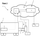
- Figure 1 shows a simplified schematic representation of a coupling arrangement 1 of a rail-guided vehicle 2, comprising a coupling head 3 for coupling to a corresponding coupling head of a coupling arrangement of another rail-guided vehicle (not shown here).
- the coupling arrangement 1 can further optionally have at least one line coupling 10 for coupling to a line coupling of a counter-coupling for transmitting electrical charge and/or data and/or liquid or gaseous media.
- a monitoring system 4 is assigned to the coupling arrangement 1.
- the monitoring system 4 is preferably designed in a decentralized manner.
- Figure 1 shows a particularly advantageous embodiment of the monitoring system 4.
- This comprises at least one data processing system 5 and at least one provision device 6 for providing and transmitting clutch arrangement data KAD and/or environmental data UD of the clutch arrangement 1 as well as at least one provision device 7 for providing and transmitting images of the clutch arrangement 1 to the data processing system 5.
- the term "data processing system” is not necessarily to be understood as a device.
- the data processing system 5 can be designed centrally or, in a particularly advantageous embodiment according to the invention as in Figure 1 reproduced via a cloud architecture for cloud computing.
- the data processing system 5 has at least one interface to the respective provision device 6 for providing and transmitting clutch arrangement data KAD and/or environmental data UD of the clutch arrangement 1 as well as a provision device 7 for providing and transmitting images of the clutch arrangement 1.
- the individual provision device 6 comprises detection devices, in particular a sensor system, which is designed to detect the operating mode and the state of the coupling arrangement 1 at least indirectly over a definable period of time.
- the following data are recorded as coupling arrangement data (KAD): operating time of the coupling arrangement or the vehicle carrying the coupling arrangement; number of coupling operations performed; GPS coordinates of the coupling arrangement; coupling speed.
- Environmental data (UD) describe the environmental influences. To characterize these, at least the outside temperatures are recorded. Other variables are conceivable, such as the type, quality, amount, and speed of precipitation, air humidity; UV radiation, etc.
- This data can be recorded via sensors mounted or integrated on the coupling assembly 1 and/or the vehicle 2.
- the provision device 7 comprises either a sensor system in the form of image sensors, which is permanently attached to and in the coupling arrangement 1 or integrated therein, for recording images of the coupling arrangement 1 and its individual components, or a mobile optical image capture device, for example a camera or smartphone, by means of which images of the coupling arrangement 1 can be recorded only when the rail vehicle is at a standstill.
- a sensor system in the form of image sensors, which is permanently attached to and in the coupling arrangement 1 or integrated therein, for recording images of the coupling arrangement 1 and its individual components
- a mobile optical image capture device for example a camera or smartphone
- the integrated sensors also allow images to be taken in areas that are not accessible from the outside using an image capture device.
- each of the individual provision devices 6, 7 comprises an interface for reading and transmitting the data to the data processing system 5.
- Each of the provision devices 6, 7 may also have a memory for storing the acquired data.
- the function of the provision device 6 for providing and transmitting coupling arrangement data KAD can be performed by a device assigned to the track-guided vehicle 2.
- this function is performed solely by a device assigned to the coupling arrangement 1.
- partial functions can be performed by both provision devices 6, 7.
- the data processing system 5 comprises at least one data memory 8 and a data processing device 9 for analyzing, evaluating, and processing the clutch arrangement data KAD, environmental data UD, and images.
- the data is preferably stored with a time stamp in the memories of the provision devices 6, 7 and/or the memory of the data processing system 5.
- the transmission of data from the provisioning devices 6, 7 is preferably wireless, for example via WLAN or mobile radio, NFC or Bluetooth.
- the data processing device 9 comprises a processor 12 configured to process data from the data memory 8 and output the processing result to interfaces.
- Such an interface represents, for example, the connection to an external device for retrieving the target specification or corrected target specification, for example, a display device in the form of a dashboard 13. This can be done wirelessly via WLAN or mobile communications, NFC, or Bluetooth.
- the data processing system 5 is implemented via a cloud architecture designed to enable cloud computing. This involves the provision of resources, e.g., servers, Storage, databases, network components, software, analytics and intelligent functions over the Internet, i.e. the Cloud 11.
- resources e.g., servers, Storage, databases, network components, software, analytics and intelligent functions over the Internet, i.e. the Cloud 11.
- Figure 2 illustrates a particularly advantageous embodiment of a method according to the invention using a flow chart.
- images ABact of the coupling assembly 1 are recorded or generated. These visually represent the actual state at that time. With attached and integrated sensors, the images AB can be recorded at specific times (request time) or continuously during operation, or in the simplest case, with minimal effort, manually while the vehicle is stationary.
- the entire coupling assembly 1, the mechanical part, and the line coupling are recorded, as well as details of the components, including surfaces, components such as seals; line connections; electrical contacts and connections, screw connections, etc.
- the individual images ABact are always recorded at different request times from the same perspective, which significantly simplifies the comparison of change behavior over a predefined period.
- the data are preferably provided with a timestamp to enable precise chronological classification of the actual state and to be merged with the clutch arrangement data KAD or the target specification Xsoll derived from it for maintenance.
- the clutch assembly data KAD are also provided in the form of operating data and, optionally, status data of the clutch assembly 1, and environmental data UD is provided to describe information from the environmental conditions to which the clutch assembly is exposed. This data can also be continuously recorded and stored in a memory 8 with an associated time stamp.
- At least the outside temperature is taken into account as environmental data UD.
- additional parameters are also taken into account, allowing load spectra to be created over predefined periods. These parameters are incorporated into the determination of the target specification for the maintenance requirement and enable even more precise target specifications. This includes the recording of the vehicle's acceleration and deceleration behavior, which are already available via the drive control and are reflected in the forces present at the clutch assembly.
- a target specification Xtarget for the maintenance request for example, a period until the next inspection and maintenance, is created from the clutch arrangement data KAD and the environment data UD at a given point in time. This is combined with the information from the images ABist (t) at the request time t, analyzed, and corrected if necessary.
- the maintenance requirement Xtarget (t) can be maintained and, if necessary, even extended to extend the period until the next required maintenance. Xtarget (t) is then set as the new target specification Xtargetnew.
- the evaluation of the actual optical condition of the coupling arrangement 1 from the images takes into account the target specification for the If a maintenance request occurs at an evaluation time and, depending on the evaluation, there is a deviation W, in particular W1 to Wn, from the target state ABsoll, a correction XK of the target specification Xsoll (t) of the maintenance request is made.
- the correction specifications XKn are determined as a function of the deviation W1 to Wn, with the correction specification that describes the shortest remaining operating time until the next maintenance or that has such an impact on the functioning of the clutch assembly that safety-relevant requirements are no longer met being set as the correction value.
- the corrected target specification is designated XKmin. If this is smaller than the target specification determined by the clutch assembly data KAD, the corrected target specification XKmin is set as the new target specification Xsollneu.
- the target value Xsollneu can then either be read out manually or automatically transferred to a decision-making instance for planning and carrying out the maintenance.
Landscapes
- Engineering & Computer Science (AREA)
- Mechanical Engineering (AREA)
- Health & Medical Sciences (AREA)
- Biomedical Technology (AREA)
- General Health & Medical Sciences (AREA)
- Vehicle Cleaning, Maintenance, Repair, Refitting, And Outriggers (AREA)
Claims (16)
- Procédé d'entretien, fondé sur l'état, d'un système d'embrayage (1) d'un véhicule guidé sur rails (2), dans lequel le système d'embrayage (1) comprend au moins une tête d'embrayage pour l'accouplement avec une tête d'embrayage opposée d'un embrayage complémentaire et facultativement au moins un embrayage de conduite (10) pour l'accouplement avec un embrayage de conduite complémentaire afin de transférer une charge électrique et/ou des données et/ou des milieux liquides ou gazeux, comprenant les étapes consistant à :a) fournir des données de système d'embrayage (KAD) sous la forme de données de fonctionnement et facultativement de données d'état du système d'embrayage ;b) fournir des données d'environnement (UD) pour décrire des informations des conditions environnantes auxquelles le système d'embrayage (1) est soumis ;c) transmettre les données fournies - données de système d'embrayage (KAD) et/ou données d'environnement (UD) - à un système de traitement de données (5) et déterminer une valeur prescrite de consigne (Xsoll) pour une demande d'entretien du système d'embrayage (1) en fonction des données de système d'embrayage (KAD) et des données d'environnement (UD) fournies ;d) acquérir des images (AB) du système d'embrayage (1) pour la reproduction optique de l'état réel et les transmettre au système de traitement de données (5) ;e) évaluer l'état optique réel du système d'embrayage (1) à partir des images (AB) avec prise en compte de la valeur prescrite de consigne (Xsoll) établie à partir des données de fonctionnement et d'état, en particulier des données de système d'embrayage (KAD) et des données d'environnement pour la demande d'entretien à un moment d'évaluation et, en fonction de l'évaluation, corriger (XK) la valeur prescrite de consigne (Xsoll) de la demande d'entretien.
- Procédé selon la revendication 1, caractérisé en ce qu'une grandeur caractérisant au moins indirectement une durée de fonctionnement restante admissible du système d'embrayage (1) jusqu'à la prochaine maintenance est déterminée en tant que valeur prescrite de consigne (Xsoll) pour la demande d'entretien en fonction des données de système d'embrayage (KAD) et des données d'environnement (UD) détectées et/ou en ce que la correction (XKn) de la valeur prescrite de consigne (Xsoll) est déterminée à l'aide d'au moins un modèle mathématique.
- Procédé selon l'une quelconque des revendications précédentes, caractérisé en ce que les données contenant les données de système d'embrayage (KAD), les données d'environnement (UD) et les images (AB) sont pourvues d'un horodatage et sont enregistrées avec celui-ci.
- Procédé selon l'une quelconque des revendications précédentes, caractérisé en ce que les données de système d'embrayage (KAD) et les données d'environnement (UD) sont détectées au moins partiellement, de préférence entièrement, côté véhicule, notamment au moyen d'un dispositif de fourniture de données (6) associé au véhicule, pendant le fonctionnement du véhicule (2) portant ou présentant le système d'embrayage (1).
- Procédé selon l'une quelconque des revendications précédentes, caractérisé en ce que les données de système d'embrayage (KAD) et les données d'environnement (UD) du système d'embrayage (1) et/ou de ses composants sont détectées au moins partiellement au moyen d'un dispositif de fourniture de données (6) associé au système d'embrayage (1).
- Procédé selon l'une quelconque des revendications précédentes, caractérisé en ce qu'au moins les données de système d'embrayage (KAD) et les données d'environnement (UD) suivantes sont détectées pour chaque système d'embrayage :- temps de fonctionnement du véhicule (2) portant le système d'embrayage (1), notamment kilométrage du véhicule- nombre de processus d'embrayage effectués- coordonnées GPS du système d'embrayage (1) ou du véhicule- vitesse d'embrayage- température extérieure- identifiant de l'embrayage.
- Procédé selon l'une quelconque des revendications précédentes, caractérisé en ce que les images optiques (AB) sont acquises et évaluées sur demande à un moment de demande ou à des intervalles de temps prédéfinis.
- Procédé selon la revendication 7,
caractérisé en ce que les étapes de procédé a) à c) selon la revendication 1 sont exécutées au moins au moment de la demande ou au cours des intervalles de temps prédéfinis pour l'acquisition des images (AB). - Procédé selon l'une quelconque des revendications 1 à 7, caractérisé en ce qu'au moins les étapes de procédé a) à c) selon la revendication 1 sont répétées de manière cyclique ou itérative, de telle sorte que la valeur prescrite de consigne (Xsoll) pour la demande d'entretien soit vérifiée et/ou ajustée.
- Procédé selon la revendication 9, caractérisé en ce que les étapes de procédé d) à e) selon la revendication 1 sont répétées de manière cyclique ou itérative.
- Procédé selon l'une quelconque des revendications précédentes, caractérisé en ce que lors de l'évaluation de l'état optique réel du système d'embrayage, l'état réel (ABist) est comparé à un état de consigne (ABsoll), dans lequel, si aucun écart entre l'état réel (ABist) et l'état de consigne (ABsoll) n'est détecté, la valeur prescrite de consigne Xsoll pour la demande d'entretien est maintenue à partir des données de système d'embrayage (KAD) et des données d'environnement (UD), et
lors de la détermination d'un écart (W1 à Wn), une modification de la valeur prescrite de consigne (Xsoll) pour une demande d'entretien est déterminée en fonction de la nature, de l'ampleur et de l'influence directe ou indirecte de l'écart sur le fonctionnement et la durée de fonctionnement restante du système d'embrayage et/ou de certains composants jusqu'à la prochaine maintenance, et est défini en tant que nouvelle valeur prescrite de consigne (Xsollneu). - Procédé selon la revendication 11, caractérisé par les étapes suivantes :- classification (Xkn) des écarts (W1 à Wn) en différentes classes en fonction de leur impact direct ou indirect sur le fonctionnement et/ou la durée de fonctionnement restante du système d'embrayage ;- prédéfinition d'au moins une modification (Xkn) de la valeur prescrite de consigne (Xsoll) pour la demande d'entretien pour chaque classe, dans lequel, au sein d'une classe, la correction (Xkmin) de la valeur prescrite de consigne est déterminée en fonction de l'écart ayant le plus grand impact sur le fonctionnement et/ou la durée de fonctionnement restante du système d'embrayage (1).
- Procédé selon l'une quelconque des revendications précédentes, caractérisé en ce que les données de système d'embrayage (KAD) et/ou les données d'environnement (UD) et/ou les images (AB) sont stockées dans une base de données qui fait partie des dispositifs de fourniture (6, 7) ou d'un dispositif de périphérie ou d'une structure en nuage (11), et la détermination de la valeur prescrite de consigne (Xsoll) pour la demande d'entretien et/ou l'évaluation de l'état optique réel (ABist) du système d'embrayage (1) à partir des images, avec prise en compte de la valeur prescrite de consigne (Xsoll) pour la demande d'entretien établie à partir des données de fonctionnement et d'état, est effectuée à un moment d'évaluation par traitement de périphérie ou informatique en nuage.
- Système de surveillance (4) pour l'entretien, fondé sur l'état, d'un système d'embrayage d'un véhicule guidé sur rails, dans lequel le système d'embrayage (1) comprend au moins une tête d'embrayage pour l'accouplement avec une tête d'embrayage opposée d'un embrayage complémentaire et facultativement au moins un embrayage de conduite (10) pour l'accouplement avec un embrayage de conduite complémentaire afin de transférer une charge électrique et/ou des données et/ou des milieux liquides ou gazeux, comprenant :- au moins un dispositif (6) destiné à détecter et fournir des données de système d'embrayage (KAD) et/ou des données d'environnement (UD) ;- un dispositif (7) destiné à acquérir/fournir des images du système d'embrayage et/ou de ses composants ;- au moins une mémoire de données (8) destinée à stocker les données de système d'embrayage (KAD), les données d'environnement (UD) et les images ;- un système de traitement de données (5) destiné à analyser et traiter les données de système d'embrayage (KAD), les données d'environnement (UD) et les images, le système de traitement de données (5) pouvant être couplé aux dispositifs de fourniture (6, 7) pour transférer des données.
- Système de surveillance (4) selon la revendication 14, caractérisé en ce que le système de traitement de données (5) est conçu sous forme de structure en nuage pour l'informatique en nuage.
- Système de surveillance (4) selon l'une des revendications 14 ou 15, caractérisé en ce que le dispositif (6) destiné à détecter et fournir les données de système d'embrayage (KAD) et/ou les données d'environnement (UD) est constitué d'un dispositif de commande associé au véhicule.
Applications Claiming Priority (2)
| Application Number | Priority Date | Filing Date | Title |
|---|---|---|---|
| DE102021117808 | 2021-07-09 | ||
| PCT/EP2022/069034 WO2023281043A1 (fr) | 2021-07-09 | 2022-07-08 | Procédé d'entretien, fondé sur l'état, d'un système d'embrayage et système de surveillance |
Publications (3)
| Publication Number | Publication Date |
|---|---|
| EP4366999A1 EP4366999A1 (fr) | 2024-05-15 |
| EP4366999B1 true EP4366999B1 (fr) | 2025-05-28 |
| EP4366999C0 EP4366999C0 (fr) | 2025-05-28 |
Family
ID=82446551
Family Applications (1)
| Application Number | Title | Priority Date | Filing Date |
|---|---|---|---|
| EP22738496.3A Active EP4366999B1 (fr) | 2021-07-09 | 2022-07-08 | Procédé d'entretien, fondé sur l'état, d'un système d'embrayage et système de surveillance |
Country Status (5)
| Country | Link |
|---|---|
| US (1) | US20240140502A1 (fr) |
| EP (1) | EP4366999B1 (fr) |
| CN (1) | CN117615952A (fr) |
| DE (1) | DE102022117032A1 (fr) |
| WO (1) | WO2023281043A1 (fr) |
Families Citing this family (2)
| Publication number | Priority date | Publication date | Assignee | Title |
|---|---|---|---|---|
| DE102024111921A1 (de) * | 2024-04-29 | 2025-10-30 | Voith Patent Gmbh | Betriebsdatenspeichereinrichtung, Zugkupplung, Waggonanordnung, System, Computerimplementiertes Verfahren zum Speichern von Betriebsdaten und nichtflüchtiges computerlesbares Speichermedium |
| DE102024126424A1 (de) * | 2024-09-13 | 2026-03-19 | Voith Patent Gmbh | Verfahren zum zustandsbasierten warten einer kupplungsanordnung eines spurgeführten fahrzeugs sowie überwachungssystem |
Family Cites Families (13)
| Publication number | Priority date | Publication date | Assignee | Title |
|---|---|---|---|---|
| KR20100083442A (ko) * | 2009-01-14 | 2010-07-22 | 진흥철도차량주식회사 | 철도차량 커플러의 안전한 연결을 위한 전후방감지시스템 및 그 방법 |
| DE102012013059A1 (de) * | 2012-07-02 | 2014-01-02 | Siemens Aktiengesellschaft | Prüfvorrichtung |
| DE102013206997A1 (de) * | 2013-04-18 | 2014-11-06 | Voith Patent Gmbh | Überwachungssystem |
| DE102013206977A1 (de) | 2013-04-18 | 2014-11-06 | Robert Bosch Gmbh | Stromregelventilbaugruppe |
| DE102014113371A1 (de) * | 2014-09-17 | 2016-03-17 | Knorr-Bremse Systeme für Schienenfahrzeuge GmbH | Verfahren zur Überwachung und Diagnose von Komponenten eines Schienenfahrzeugs, mit erweiterbarer Auswertungssoftware |
| DE102015205978A1 (de) | 2015-04-02 | 2016-10-06 | Bayerische Motoren Werke Aktiengesellschaft | Dokumentieren eines Kraftfahrzeug-Zustands |
| FR3036676B1 (fr) | 2015-05-29 | 2019-05-24 | Metrolab | Systeme automatique de couplage de vehicules ferroviaires et procede associe |
| GB201611326D0 (en) * | 2016-06-29 | 2016-08-10 | Optasense Holdings Ltd | Distributed fibre optic sensing for rail monitoring |
| US10618532B2 (en) | 2016-12-11 | 2020-04-14 | Jiaxing Broadsens Technology, Ltd. | Train coupler structural health monitoring system |
| US20190178754A1 (en) * | 2017-12-08 | 2019-06-13 | Jiaxing Broadsens Technology, Ltd. | Method and system for monitoring structural status of railcar draft gear |
| DE102019106961A1 (de) | 2019-03-19 | 2020-09-24 | Voith Patent Gmbh | Kraftübertragungselement für eine kupplung eines spurgeführten fahrzeuges sowie verfahren zum überwachen der funktionsweise einer kupplungsanordnung |
| DE102019109417A1 (de) * | 2019-04-10 | 2020-10-15 | Voith Patent Gmbh | Messmodul für eine Kupplungseinrichtung für ein spurgeführtes Fahrzeug, Kupplungseinrichtung mit einem derartigen Modul und Verfahren zur mechanischen Kopplung derartiger Fahrzeuge |
| CN112896227B (zh) * | 2021-02-08 | 2022-09-13 | 中车青岛四方车辆研究所有限公司 | 车钩缓冲装置的状态监测方法及系统 |
-
2022
- 2022-07-08 CN CN202280048419.7A patent/CN117615952A/zh active Pending
- 2022-07-08 DE DE102022117032.2A patent/DE102022117032A1/de active Pending
- 2022-07-08 WO PCT/EP2022/069034 patent/WO2023281043A1/fr not_active Ceased
- 2022-07-08 EP EP22738496.3A patent/EP4366999B1/fr active Active
-
2024
- 2024-01-09 US US18/408,104 patent/US20240140502A1/en active Pending
Also Published As
| Publication number | Publication date |
|---|---|
| CN117615952A (zh) | 2024-02-27 |
| DE102022117032A1 (de) | 2023-01-12 |
| EP4366999C0 (fr) | 2025-05-28 |
| EP4366999A1 (fr) | 2024-05-15 |
| WO2023281043A1 (fr) | 2023-01-12 |
| US20240140502A1 (en) | 2024-05-02 |
Similar Documents
| Publication | Publication Date | Title |
|---|---|---|
| EP2212180B1 (fr) | Détermination de la durée de vie résiduelle d'un élément de véhicule | |
| EP3194229B2 (fr) | Procédé de surveillance et de diagnostic de composants d'un véhicule ferroviaire avec un logiciel d'evaluation extensible | |
| EP2877383B1 (fr) | Procédé de diagnostic pour véhicules ferroviaires | |
| DE102012202914A1 (de) | Diagnoseverfahren und Diagnosevorrichtung für eine Fahrzeugkomponente eines Fahrzeugs | |
| DE102012202540A1 (de) | Diagnoseverfahren und Diagnosevorrichtung für eine Fahrzeugkomponente eines Fahrzeugs | |
| EP4366999B1 (fr) | Procédé d'entretien, fondé sur l'état, d'un système d'embrayage et système de surveillance | |
| EP3517398B1 (fr) | Procédé de surveillance d'état de l'espace intérieur ainsi que véhicule doté d'un dispositif de surveillance d'état de l'espace intérieur | |
| DE102017200855A1 (de) | Verfahren und System zur Diagnose von Komponenten eines Fahrzeugs | |
| DE102012206859A1 (de) | Verfahren zum Erzeugen von Handlungsempfehlungen für den Führer eines Schienenfahrzeugs oder Steuersignalen für das Schienenfahrzeug mittels eines Fahrerassistenzsystems und Fahrassistenzsystem | |
| DE102014207828A1 (de) | Verfahren zur Bereitstellung einer Diagnosenachricht bei einem Schienenfahrzeug | |
| AT516487A1 (de) | Zustandsdiagnose von Schienenfahrzeugrädern | |
| DE102015120838A1 (de) | Verfahren und System zur Diagnose eines Bremsbelagverschleißes | |
| DE102021110536A1 (de) | Verfahren zur Überwachung einer Förderanlage mit Förderelementen, Computerprogramm sowie elektronisch lesbarer Datenträger | |
| WO2019215017A1 (fr) | Procédé, dispositif et support d'informations lisible par un ordinateur pourvu d'instructions destinées à contrôler et à valider des données de fonctionnement dans l'actionneur d'un véhicule automobile autonome | |
| WO2004022406A1 (fr) | Procede et dispositif de controle de l'etat de mecanismes de deplacement de vehicules | |
| DE102008049224A1 (de) | Verfahren und Vorrichtung zum Überprüfen mindestens eines Laufwerks eines auf einem Gleis fahrbaren Schienenfahrzeugs auf einen Defekt | |
| DE102016224622A1 (de) | Verfahren und Vorrichtung zur Weichendiagnose unter Last | |
| DE102016213133A1 (de) | Verfahren sowie Vorrichtung zum automatischen Prüfen von Bremsen eines spurgebundenen Fahrzeugs | |
| DE102007015762A1 (de) | Datenaufzeichnungssystem und Verfahren zur Erfassung von Daten mittels eines Datenaufzeichnungssystems | |
| DE102019107242A1 (de) | Diagnoseverfahren, Diagnosesystem und Kraftfahrzeug | |
| DE102015214987B4 (de) | Bestimmung eines defekten Bauteils eines Fahrzeugs | |
| EP4711232A1 (fr) | Procédé de maintenance basée sur l'état d'un système d'embrayage d'un véhicule guidé et système de surveillance | |
| DE102022207418A1 (de) | Bauteilverschleiß-Erkennung bei autonomer Fahrzeugflotte mit Schwarmdaten und Auswahl des Einsatzszenarios eines Einzelfahrzeugs | |
| EP3963291B1 (fr) | Ensemble capteur conçu pour surveiller un système technique et procédé pour faire fonctionner un ensemble capteur | |
| WO2000032458A1 (fr) | Procede et dispositif pour determiner des etats et/ou des changements d'etat dans des installations de trafic ferroviaire |
Legal Events
| Date | Code | Title | Description |
|---|---|---|---|
| STAA | Information on the status of an ep patent application or granted ep patent |
Free format text: STATUS: UNKNOWN |
|
| STAA | Information on the status of an ep patent application or granted ep patent |
Free format text: STATUS: THE INTERNATIONAL PUBLICATION HAS BEEN MADE |
|
| PUAI | Public reference made under article 153(3) epc to a published international application that has entered the european phase |
Free format text: ORIGINAL CODE: 0009012 |
|
| STAA | Information on the status of an ep patent application or granted ep patent |
Free format text: STATUS: REQUEST FOR EXAMINATION WAS MADE |
|
| 17P | Request for examination filed |
Effective date: 20240209 |
|
| AK | Designated contracting states |
Kind code of ref document: A1 Designated state(s): AL AT BE BG CH CY CZ DE DK EE ES FI FR GB GR HR HU IE IS IT LI LT LU LV MC MK MT NL NO PL PT RO RS SE SI SK SM TR |
|
| DAV | Request for validation of the european patent (deleted) | ||
| DAX | Request for extension of the european patent (deleted) | ||
| GRAP | Despatch of communication of intention to grant a patent |
Free format text: ORIGINAL CODE: EPIDOSNIGR1 |
|
| STAA | Information on the status of an ep patent application or granted ep patent |
Free format text: STATUS: GRANT OF PATENT IS INTENDED |
|
| INTG | Intention to grant announced |
Effective date: 20250117 |
|
| GRAS | Grant fee paid |
Free format text: ORIGINAL CODE: EPIDOSNIGR3 |
|
| GRAA | (expected) grant |
Free format text: ORIGINAL CODE: 0009210 |
|
| STAA | Information on the status of an ep patent application or granted ep patent |
Free format text: STATUS: THE PATENT HAS BEEN GRANTED |
|
| AK | Designated contracting states |
Kind code of ref document: B1 Designated state(s): AL AT BE BG CH CY CZ DE DK EE ES FI FR GB GR HR HU IE IS IT LI LT LU LV MC MK MT NL NO PL PT RO RS SE SI SK SM TR |
|
| REG | Reference to a national code |
Ref country code: GB Ref legal event code: FG4D Free format text: NOT ENGLISH |
|
| REG | Reference to a national code |
Ref country code: CH Ref legal event code: EP |
|
| REG | Reference to a national code |
Ref country code: IE Ref legal event code: FG4D Free format text: LANGUAGE OF EP DOCUMENT: GERMAN Ref country code: DE Ref legal event code: R096 Ref document number: 502022004088 Country of ref document: DE |
|
| U01 | Request for unitary effect filed |
Effective date: 20250528 |
|
| U07 | Unitary effect registered |
Designated state(s): AT BE BG DE DK EE FI FR IT LT LU LV MT NL PT RO SE SI Effective date: 20250605 |
|
| PG25 | Lapsed in a contracting state [announced via postgrant information from national office to epo] |
Ref country code: ES Free format text: LAPSE BECAUSE OF FAILURE TO SUBMIT A TRANSLATION OF THE DESCRIPTION OR TO PAY THE FEE WITHIN THE PRESCRIBED TIME-LIMIT Effective date: 20250528 |
|
| PG25 | Lapsed in a contracting state [announced via postgrant information from national office to epo] |
Ref country code: NO Free format text: LAPSE BECAUSE OF FAILURE TO SUBMIT A TRANSLATION OF THE DESCRIPTION OR TO PAY THE FEE WITHIN THE PRESCRIBED TIME-LIMIT Effective date: 20250828 Ref country code: GR Free format text: LAPSE BECAUSE OF FAILURE TO SUBMIT A TRANSLATION OF THE DESCRIPTION OR TO PAY THE FEE WITHIN THE PRESCRIBED TIME-LIMIT Effective date: 20250829 |
|
| PG25 | Lapsed in a contracting state [announced via postgrant information from national office to epo] |
Ref country code: PL Free format text: LAPSE BECAUSE OF FAILURE TO SUBMIT A TRANSLATION OF THE DESCRIPTION OR TO PAY THE FEE WITHIN THE PRESCRIBED TIME-LIMIT Effective date: 20250528 |
|
| U20 | Renewal fee for the european patent with unitary effect paid |
Year of fee payment: 4 Effective date: 20250905 |
|
| PG25 | Lapsed in a contracting state [announced via postgrant information from national office to epo] |
Ref country code: HR Free format text: LAPSE BECAUSE OF FAILURE TO SUBMIT A TRANSLATION OF THE DESCRIPTION OR TO PAY THE FEE WITHIN THE PRESCRIBED TIME-LIMIT Effective date: 20250528 |
|
| PG25 | Lapsed in a contracting state [announced via postgrant information from national office to epo] |
Ref country code: RS Free format text: LAPSE BECAUSE OF FAILURE TO SUBMIT A TRANSLATION OF THE DESCRIPTION OR TO PAY THE FEE WITHIN THE PRESCRIBED TIME-LIMIT Effective date: 20250828 |
|
| PG25 | Lapsed in a contracting state [announced via postgrant information from national office to epo] |
Ref country code: IS Free format text: LAPSE BECAUSE OF FAILURE TO SUBMIT A TRANSLATION OF THE DESCRIPTION OR TO PAY THE FEE WITHIN THE PRESCRIBED TIME-LIMIT Effective date: 20250928 |
|
| PG25 | Lapsed in a contracting state [announced via postgrant information from national office to epo] |
Ref country code: SM Free format text: LAPSE BECAUSE OF FAILURE TO SUBMIT A TRANSLATION OF THE DESCRIPTION OR TO PAY THE FEE WITHIN THE PRESCRIBED TIME-LIMIT Effective date: 20250528 |
|
| PG25 | Lapsed in a contracting state [announced via postgrant information from national office to epo] |
Ref country code: CZ Free format text: LAPSE BECAUSE OF FAILURE TO SUBMIT A TRANSLATION OF THE DESCRIPTION OR TO PAY THE FEE WITHIN THE PRESCRIBED TIME-LIMIT Effective date: 20250528 |
|
| PG25 | Lapsed in a contracting state [announced via postgrant information from national office to epo] |
Ref country code: SK Free format text: LAPSE BECAUSE OF FAILURE TO SUBMIT A TRANSLATION OF THE DESCRIPTION OR TO PAY THE FEE WITHIN THE PRESCRIBED TIME-LIMIT Effective date: 20250528 |
|
| REG | Reference to a national code |
Ref country code: CH Ref legal event code: H13 Free format text: ST27 STATUS EVENT CODE: U-0-0-H10-H13 (AS PROVIDED BY THE NATIONAL OFFICE) Effective date: 20260224 |
|
| PLBE | No opposition filed within time limit |
Free format text: ORIGINAL CODE: 0009261 |
|
| STAA | Information on the status of an ep patent application or granted ep patent |
Free format text: STATUS: NO OPPOSITION FILED WITHIN TIME LIMIT |
|
| REG | Reference to a national code |
Ref country code: CH Ref legal event code: L10 Free format text: ST27 STATUS EVENT CODE: U-0-0-L10-L00 (AS PROVIDED BY THE NATIONAL OFFICE) Effective date: 20260409 |
|
| PG25 | Lapsed in a contracting state [announced via postgrant information from national office to epo] |
Ref country code: CH Free format text: LAPSE BECAUSE OF NON-PAYMENT OF DUE FEES Effective date: 20250731 |