EP4367484B1 - Procédé d'étalonnage pour système de mesure de débit, système de mesure de débit et produit programme d'ordinateur - Google Patents
Procédé d'étalonnage pour système de mesure de débit, système de mesure de débit et produit programme d'ordinateur Download PDFInfo
- Publication number
- EP4367484B1 EP4367484B1 EP22786804.9A EP22786804A EP4367484B1 EP 4367484 B1 EP4367484 B1 EP 4367484B1 EP 22786804 A EP22786804 A EP 22786804A EP 4367484 B1 EP4367484 B1 EP 4367484B1
- Authority
- EP
- European Patent Office
- Prior art keywords
- ultrasonic
- pulse
- flow
- flow measurement
- pipe wall
- Prior art date
- Legal status (The legal status is an assumption and is not a legal conclusion. Google has not performed a legal analysis and makes no representation as to the accuracy of the status listed.)
- Active
Links
Images


Classifications
-
- G—PHYSICS
- G01—MEASURING; TESTING
- G01F—MEASURING VOLUME, VOLUME FLOW, MASS FLOW OR LIQUID LEVEL; METERING BY VOLUME
- G01F25/00—Testing or calibration of apparatus for measuring volume, volume flow or liquid level or for metering by volume
-
- G—PHYSICS
- G01—MEASURING; TESTING
- G01F—MEASURING VOLUME, VOLUME FLOW, MASS FLOW OR LIQUID LEVEL; METERING BY VOLUME
- G01F25/00—Testing or calibration of apparatus for measuring volume, volume flow or liquid level or for metering by volume
- G01F25/10—Testing or calibration of apparatus for measuring volume, volume flow or liquid level or for metering by volume of flowmeters
-
- G—PHYSICS
- G01—MEASURING; TESTING
- G01F—MEASURING VOLUME, VOLUME FLOW, MASS FLOW OR LIQUID LEVEL; METERING BY VOLUME
- G01F1/00—Measuring the volume flow or mass flow of fluid or fluent solid material wherein the fluid passes through a meter in a continuous flow
- G01F1/66—Measuring the volume flow or mass flow of fluid or fluent solid material wherein the fluid passes through a meter in a continuous flow by measuring frequency, phase shift or propagation time of electromagnetic or other waves, e.g. using ultrasonic flowmeters
-
- G—PHYSICS
- G01—MEASURING; TESTING
- G01F—MEASURING VOLUME, VOLUME FLOW, MASS FLOW OR LIQUID LEVEL; METERING BY VOLUME
- G01F1/00—Measuring the volume flow or mass flow of fluid or fluent solid material wherein the fluid passes through a meter in a continuous flow
- G01F1/66—Measuring the volume flow or mass flow of fluid or fluent solid material wherein the fluid passes through a meter in a continuous flow by measuring frequency, phase shift or propagation time of electromagnetic or other waves, e.g. using ultrasonic flowmeters
- G01F1/662—Constructional details
-
- G—PHYSICS
- G01—MEASURING; TESTING
- G01F—MEASURING VOLUME, VOLUME FLOW, MASS FLOW OR LIQUID LEVEL; METERING BY VOLUME
- G01F1/00—Measuring the volume flow or mass flow of fluid or fluent solid material wherein the fluid passes through a meter in a continuous flow
- G01F1/66—Measuring the volume flow or mass flow of fluid or fluent solid material wherein the fluid passes through a meter in a continuous flow by measuring frequency, phase shift or propagation time of electromagnetic or other waves, e.g. using ultrasonic flowmeters
- G01F1/667—Arrangements of transducers for ultrasonic flowmeters; Circuits for operating ultrasonic flowmeters
Definitions
- the invention relates to a calibration method for a flow measuring system.
- the invention also relates to a flow measuring system that is suitable for carrying out such a calibration method.
- the invention also relates to a computer program product for simulating an operating behavior of a corresponding flow measuring system.
- the measuring tube belongs to a mechanical vibration system that can be excited to vibration by an exciter.
- the pipe wall thickness is determined using a recorded excitation input variable and a response variable of the vibration system, which are inserted into a transfer equation.
- the publication DE 10 2015 107 752 A1 discloses a method for determining a pipe wall resonance frequency of a pipeline in the area of a measuring point.
- the method comprises emitting an ultrasonic signal and detecting a received signal.
- the pipe wall resonance frequency is determined based on a transfer function of a measuring point. Based on this, a pipe wall thickness and/or a pipe wall material can be determined.
- the patent application DE 10 2007 019 689 A1 discloses a device for determining a volume flow of a medium, which has two ultrasonic sensors arranged along a pipe axis, via which ultrasonic pulses can be emitted diagonally into the pipe to measure the volume flow. At least one of the ultrasonic sensors has piezoelectric elements that serve as diagnostic sensors, which are designed to determine diagnostic data To emit ultrasonic pulses into the pipe perpendicular to the pipe axis.
- An ultrasonic flow meter which has several piezoelectric transducers.
- a first and second piezoelectric transducer are designed to send ultrasonic pulses obliquely into a pipe on which the ultrasonic flow meter is attached.
- a third piezoelectric transducer is positioned between the first and second transducers and is designed to send and receive ultrasonic pulses perpendicular to the pipe axis. Based on this, an inner diameter of the pipe can be determined.
- US 2017/0153136 A1 shows a flow meter that can be clamped onto a pipe and has an automatic function for determining the pipe wall thickness. To do this, a resonance frequency is excited and recorded when a frequency spectrum is swept through. Based on this and an indication of the pipe's outer diameter and a material specification of the pipe wall, the pipe wall thickness is determined.
- Flow meters are used in a variety of applications, such as process plants, to measure flow rates or throughputs in pipes. Increasing demands are placed on measurement accuracy, durability and ease of installation.
- the invention is based on the task of providing a flow measurement system and an associated calibration method that offers an improvement in at least one of the aspects outlined.
- the task is solved by a method according to the invention for calibrating a flow measuring system.
- the flow measuring system is mounted on a pipe which encloses a medium in its lumen, the flow of which and thus its flow rate is to be measured.
- the medium can be, for example, a gas, a liquid, a suspension, a foam, or a thick substance.
- the method comprises a first step in which the flow measurement system is provided in an active operating state and is suitable for non-invasive flow measurement.
- the flow measurement system comprises a first flow sensor which is mounted on the pipe. In the active state, the first flow sensor is suitable for emitting an ultrasonic pulse through a pipe wall into the lumen of the pipe.
- the method also includes a second step in which an ultrasonic pulse is emitted into the pipe wall using a first or second ultrasonic head.
- the ultrasonic pulse can be introduced directly into the pipe wall in the area of the ultrasonic heads.
- the first and second ultrasonic heads belong to the first flow sensor and are assigned to it.
- the emitted ultrasonic pulse passes through the pipe wall and is reflected on an inner side of the pipe wall.
- the reflected ultrasonic pulse is received in the second step as an ultrasonic echo using the second ultrasonic head. Between the emission of the ultrasonic pulse and the reception of the ultrasonic echo there is a signal propagation time in which the pipe wall is passed through twice.
- the method also has a third step in which the signal propagation time of the ultrasonic pulse or ultrasonic echo is determined. Based on the signal propagation time, a pipe wall thickness is determined in the third step. For this purpose, at least one alignment angle between a pipe axis and a main propagation direction of the ultrasonic pulse is taken into account. This creates a calculable relationship between the signal propagation time and the pipe wall thickness.
- a pipe inner diameter can be determined in the third step based on the pipe wall thickness and information about the pipe outer diameter. Such information can be provided, for example, by user input.
- the method comprises a fourth step in which at least one calibration parameter of the first flow sensor is set.
- the at least one calibration parameter includes the pipe wall thickness and/or the pipe inner diameter determined in the third step.
- Ultrasound heads offer an increased degree of measurement accuracy, so that the pipe wall thickness can be determined with increased precision using the method according to the invention.
- the method can be carried out automatically, which allows the flow measuring system to be quickly recalibrated during operation.
- the flow measuring system can be adapted to varying pipe wall thicknesses, and thus varying pipe inner diameters.
- the pipe wall thickness can be reduced by corrosion of the pipe wall, or increased by contamination on the pipe wall.
- pipe walls are manufactured with reduced precision, so that an exact pipe wall thickness is often not known. The effects of such effects on the measurement accuracy of the flow measuring system can be compensated for using the method according to the invention.
- the at least one calibration parameter can be set, for example, by storing corresponding values in an evaluation unit of the flow measuring system.
- the ultrasonic pulse is emitted in the second step of the method in a diagonal direction relative to the pipe axis into the medium, and thus into the pipe wall.
- the second ultrasonic head and the ultrasonic reflector can be arranged in relation to the first ultrasonic head in such a way that the main propagation directions of the ultrasonic pulse and the flow measurement pulse do not cross.
- a measurement operation is thus ensured in a simple manner while simultaneously carrying out the claimed method.
- the inventive emission of the ultrasonic pulse into the medium, and thus into the pipe wall, in a diagonal direction allows a surface roughness on an inner side of the pipe wall to be determined.
- an intensity of the ultrasonic echo received in the second step can be recorded. This is compared with an intensity of the emitted ultrasonic pulse.
- the rougher the inner side of the pipe wall the the stronger the reflection back to the second ultrasound head.
- the lower the ratio of the intensity of the received ultrasound echo and the intensity of the emitted ultrasound pulse for example, the lower the surface roughness of the inside of the pipe wall.
- the surface roughness of the inside of the pipe wall can be determined.
- a table of values and/or information about the material of the pipe wall can be taken into account for this purpose. This allows a precise determination of the throughput of medium in the pipe, particularly when using the Hagen-Poiseuille equation.
- the determined surface roughness of the inside of the pipe wall is set as a calibration parameter in the fourth step according to the invention. The accuracy achievable with the claimed method through calibration is thus further increased.
- further analyses can be carried out to determine the pipe wall thickness and the surface roughness.
- the second ultrasound head of the first flow sensor is assigned an ultrasound reflector that is suitable for deflecting the ultrasound pulse that is emitted in the second step.
- the ultrasound pulse which is used to determine the pipe wall thickness, can be deflected away from a flow measurement pulse. This avoids spatial superposition of the ultrasound pulse with the flow measurement pulse. Consequently, simultaneous measurement and implementation of the claimed method are possible.
- the ultrasound reflector has dimensions that correspond to a multiple of the wavelength of the ultrasound pulse.
- the ultrasound pulse can be easily directed by the ultrasound reflector in a direction that is favorable for determining the pipe wall thickness.
- the first ultrasound head can be designed to emit the flow measurement pulse.
- the first ultrasound head can therefore be operated independently of the second ultrasound head.
- the first and second ultrasound heads can thus be designed to be optimized for their respective tasks. This allows the use of simple and cost-effective ultrasound heads for the first and second ultrasound heads.
- the first and second ultrasound heads can also be designed as an integrated combined ultrasound head.
- the first and second ultrasound heads can be designed as independently controllable segments of the combined ultrasound head.
- the first and second ultrasound heads can use a common piezo element, which can be controlled segment by segment via independent electrodes.
- Such a combined ultrasound head is compact and thus offers space savings.
- a corresponding adaptation of a second flow sensor is unnecessary.
- the claimed method can be adapted overall to different requirements in terms of compactness and cost efficiency.
- the ultrasonic pulse that is emitted in the second step can be distinguished from the flow measurement pulse by an electronic filter, in particular a bandpass filter.
- the electronic filter is formed in the evaluation unit of the flow measurement system. This allows the claimed method to be carried out at the same time as a measurement operation. Overlays between the flow measurement pulse and the ultrasonic pulse or its ultrasonic echo can also be accepted. This makes it possible to avoid operation of the first and second ultrasonic heads coordinated over time slices. For example, the flow measurement pulse and the ultrasonic pulse can have different frequencies or distinguishable pulse patterns.
- the electronic filter can be formed by electronic components and/or an algorithm in the flow measurement system.
- the ultrasonic pulse and the flow measurement pulse can be designed to be distinguishable by emitting them at different times.
- the first and second ultrasonic heads are operated in a time slice operation. Because the pipe wall thickness is less than the pipe inner diameter, the signal propagation time of the ultrasonic pulse, which is used to determine the pipe wall thickness, is shorter than the signal propagation time of a flow measurement pulse, which is used to measure the flow rate of the medium.
- a first time slice for measuring the pipe wall thickness can be designed to be shorter than a second time slice in which the flow rate of the medium, i.e. its throughput, is measured using the flow measurement pulse.
- the measuring operation in which the flow rate of the medium is measured is only minimally affected by the claimed method.
- the claimed method also allows a compact design of the first flow sensor in which the main propagation directions of the ultrasonic pulse and the flow measurement pulse intersect.
- the ultrasonic pulse that is emitted in the second step can have a bandwidth of 25 kHz to 8 MHz, preferably from 40 kHz to 6 MHz, more preferably from 50 kHz to 4 MHz.
- the ultrasonic pulse can have a pulse duration of 0.1 ⁇ s to 5.0 ms, preferably from 0.15 ⁇ s to 3 ms, particularly preferably from 0.25 ⁇ s to 1.0 ms.
- the invention is based, among other things, on the surprising finding that a correspondingly broadband and short ultrasonic pulse in the second step also produces an ultrasonic echo that enables the pipe wall thickness to be determined precisely. In particular, with such an ultrasonic pulse, even when emitted in a diagonal direction, a sufficient ultrasonic echo is reflected that allows the pipe wall thickness to be determined.
- the third step can be carried out taking into account an indication of a material of the pipe wall.
- the speed of sound in the pipe wall is essentially determined by the material of the pipe wall.
- the information about the material of the pipe wall can be provided directly via user input and/or by information about the type of pipe, which can be stored in the evaluation unit, for example.
- information about a connection of the first flow sensor to the pipe can also be taken into account.
- an expected intensity of the ultrasonic echo can be specified.
- existing corrosion of the pipe or contamination of the pipe can also be determined based on the pipe wall thickness determined in the third step.
- the extent of the corrosion or contamination can also be determined.
- the pipe wall thickness determined in the third step is compared with historical values for the pipe wall thickness.
- a difference can be formed between the pipe wall thickness determined in the third step and at least one historical value for the pipe wall thickness. If the difference exceeds an adjustable threshold value, a warning can be issued to a user. This allows required maintenance processes to be identified at an early stage, which reduces downtimes of process plants in which the claimed method is carried out.
- an evaluation unit which can be used in a flow measurement system that has at least one first flow sensor.
- the evaluation unit is suitable for receiving and evaluating measurement signals from the first flow sensor.
- the evaluation unit can be designed to output a determined flow of a medium in a pipe on which the flow system can be mounted.
- the evaluation unit is designed to use at least one embodiment of the method outlined above. Accordingly, the features of the method and/or the flow measurement system described below can be transferred to the evaluation unit.
- the evaluation unit can be designed as a local evaluation unit that is incorporated in one of the flow sensors.
- the evaluation unit can also be designed as an industrial controller, such as a so-called programmable logic controller, as a master computer, as a computer cloud or as a combination of these.
- the outlined task is also solved by a flow measuring system according to the invention.
- the flow measuring system comprises a first and a second flow sensor, which can be mounted on a pipe in order to non-invasively measure the flow of a medium in the pipe.
- the first flow meter comprises a first ultrasound head for emitting a flow measuring pulse.
- the second flow sensor is designed to receive an echo of the flow measuring pulse.
- the first and second flow sensors work together to determine the flow of the medium in the pipe, for example via an evaluation unit.
- the first flow sensor is provided with a second ultrasound head, which is designed to determine an inner pipe diameter.
- the second ultrasound head can, for example, be designed to carry out at least one embodiment of the method outlined above.
- the described features of the method can therefore be directly transferred to the flow measuring system according to the invention.
- the flow measuring system has an evaluation unit according to one of the embodiments outlined above.
- the second ultrasound head can be designed to emit an ultrasound pulse and/or receive an ultrasound echo.
- the ultrasound pulse can be introduced directly into the pipe wall by the second ultrasound head.
- the ultrasound pulse is transmitted in an opposite Area on the inside of the pipe wall is reflected as an ultrasonic echo and can be received by the second ultrasonic head.
- the second ultrasonic head can be designed to emit the ultrasonic pulse in relation to a pipe axis, in a diagonal direction or essentially in a radial direction.
- the first flow sensor has at least one ultrasonic reflector, which is designed to deflect the ultrasonic pulse emitted by the first and/or second ultrasonic head.
- the ultrasonic reflector can be arranged such that the ultrasonic pulse is sent essentially in a radial direction into the pipe wall. This ensures effective reflection of the ultrasonic pulse as an ultrasonic echo from an opposite area on the inside of the pipe wall back to the second ultrasonic head. Such a clear ultrasonic echo in turn allows precise determination of the pipe's inner diameter.
- the ultrasonic reflector can be partially transparent or designed as a switchable ultrasonic reflector. Using a partially transparent ultrasonic reflector, only the ultrasonic pulse or the ultrasonic echo can be deflected, but not the flow measurement pulse. Instead, the flow measurement pulse passes through the partially transparent ultrasonic reflector. This means that the ultrasonic reflector can have increased dimensions and can be manufactured in a simple, cost-effective manner.
- the switchable ultrasonic reflector can be switched on and off in its deflection effect. For example, a time slice operation can be implemented in which the first and second ultrasonic heads are positioned close to one another and emit essentially in the same direction. Using such reflectors, different variants of the method outlined above can be reliably implemented.
- the claimed flow measurement system also allows several embodiments of the claimed method to be implemented cost-effectively.
- the claimed flow measurement system can be easily adapted to a large number of applications. Furthermore, the object described at the outset is achieved by a computer program product according to the invention.
- the computer program product is designed to simulate an operating behavior of a flow measurement system. According to the invention, the computer program product comprises commands that cause a computer to simulate the operating behavior of the flow measurement system.
- the computer program product can be set up to simulate the operating behavior of the flow measuring system by specifying its structure, i.e. storing an image of it.
- the operating behavior can also be represented by an abstracted calculation model that is independent of the spatial structure of the flow measuring system.
- the operating behavior can also be determined using a combination of these.
- the flow measuring system to be simulated is designed according to one of the embodiments described above.
- the computer program product can have a physics module for simulation in which the flow measuring system is represented and, for example, its ultrasonic-acoustic or signaling behavior can be reproduced under adjustable operating conditions.
- the adjustable operating conditions include a temperature of the medium in the pipe, a speed of sound in the medium, a viscosity of the medium, a flow rate of the medium, a pressure of the medium, a flow behavior, in particular a turbulence behavior or a flow rate profile.
- the computer program product can have a data interface via which corresponding data can be specified via a user input and/or other simulation-oriented computer program products.
- the computer program product may also have a data interface for outputting simulation results to a user and/or other simulation-oriented Computer program products.
- signal propagation times recorded by ultrasound heads or other sensor values of a system in which the flow measurement system is used can be checked for plausibility.
- a detected corrosion, contamination or surface roughness of an inner side of the pipe wall can plausibly be present after a known operating period, or whether a defective component in the flow measurement system is to be expected.
- the invention is based, among other things, on the surprising finding that the methods outlined above can be modeled with increased precision with relatively little computing effort, for example the reflection behavior on the pipe wall opposite the first flow sensor. Accordingly, the computer program product according to the invention provides a comprehensive and at the same time computing capacity-saving option for monitoring and/or testing a corresponding flow measurement system.
- the computer program product can be designed as a so-called digital twin, as described, for example, in the publication US 2017/286572 A1 described in more detail.
- the revelation content of US 2017/286572 A1 is incorporated by reference into the present application.
- the computer program product can be monolithic, i.e. can be executed entirely on a hardware platform.
- the computer program product can be modular and comprise a plurality of subprograms that can be executed on separate hardware platforms and interact via a communicative data connection.
- the computer program product can be designed to be executable in a computer cloud.
- the computer program product according to the invention can be used to test and/or optimize a flow measurement system by simulation, for example in the case of a planned retrofit in a process plant.
- the flow measuring system is attached to a pipe through which a medium flows in order to carry out a measuring operation.
- the measuring operation is used to measure a flow rate of the medium, and thus its throughput.
- the flow measuring system which comprises at least one first flow sensor, is also used during the measuring operation to determine a pipe wall thickness of the pipe.
- the measuring accuracy of the measuring operation is influenced, among other things, by the pipe wall thickness, which is stored as a calibration parameter in an evaluation unit of the flow measuring system.
- the flow measuring system is accordingly used for adjustable, ongoing recalibration during the measuring operation. In this case, ongoing recalibration is understood to mean determining the pipe wall thickness during the measuring operation.
- a user can set the intervals at which the recalibration is to be carried out by determining the pipe wall thickness as a calibration parameter.
- the flow measuring system can be designed according to at least one of the embodiments outlined above.
- FIG 1 a structure of a claimed flow measuring system 30 is shown schematically in longitudinal section.
- the flow measuring system 30 is in a stage of a claimed method 100 for calibrating the flow measuring system 30.
- the flow measuring system 30 comprises a first flow sensor 10 and a second flow sensor 20, which are mounted on a pipe 12.
- the first and second flow sensors 10, 20 are coupled to an evaluation unit 40, which also belongs to the flow measuring system 40.
- the flow measuring system 30 is in an active, i.e. functional, state, so that a first step 110 of the claimed method 100 in FIG 1 is closed.
- the pipe 12 has a pipe wall 13, through which a medium 11 is enclosed, which flows along a pipe axis 15 through the pipe 12.
- the medium 11 has a temperature 14 and a flow rate 16.
- FIG 1 shows a measuring operation in which a flow measurement pulse 35 is sent into the medium 11 by a first ultrasonic head 22 in the first flow sensor 10. An echo 37 of the The flow measurement pulse 35 is reflected on a pipe wall 18 opposite the first and second flow sensors 10, 20. The echo 37 is received by a further ultrasound head 26, which is arranged in the second flow sensor 20. For the flow measurement pulse 35 and its echo 37, a signal runtime results, which can be evaluated to determine the flow velocity 16.
- measurement signals 45 are transmitted from the first and second flow sensors 10, 20 to the evaluation unit 40.
- the flow measuring system 30 is prepared to carry out further steps of the method 100, as described below.
- the operating behavior of the flow measuring system 30 is simulated by a computer program product 50 (not shown in detail), which is designed as a digital twin of at least the first flow sensor 10.
- the first flow sensor 10 comprises a first ultrasonic head 22, which is suitable for emitting a flow measurement pulse 35 (not shown).
- the first flow sensor 10 is, as in FIG 1 shown, mounted on the pipe 12, i.e. its pipe wall 13 and in an active operating state.
- the first step 110 of the method 100 is according to FIG 2
- the first ultrasound head 22 is also designed to emit an ultrasound pulse 25 in a second step 120 of the method 100, by means of which the pipe wall thickness 19 is to be determined.
- the ultrasound pulse 25 propagates along a main propagation direction 36, which in FIG 2 is shown by the arrow directions.
- the ultrasonic pulse 25 is deflected at the pipe wall 13 and enters the pipe wall 13 in a diagonal direction with respect to the pipe axis 15. Furthermore, the ultrasonic pulse 25 is reflected in an opposite area on an inner side 17 of the pipe wall 18 as an ultrasonic echo 29. The ultrasonic echo 29 is emitted from the pipe wall 13 is also deflected. The ultrasonic echo 29 is received by a second ultrasonic head 24, which is arranged in the first flow sensor 10. Based on measurement signals 45 from the first and second ultrasonic heads 22, 24, the pipe wall thickness 19 is determined in the evaluation unit 40. For this purpose, a signal propagation time of the ultrasonic pulse 25 and its ultrasonic echo 29 is determined using the measurement signals 45.
- a speed of sound in the pipe wall 13 can be determined. Based on this, based on the signal propagation time of the ultrasonic pulse 25 and its ultrasonic echo 29 from the first ultrasonic head 22 to the second ultrasonic head 24, the pipe wall thickness 19 can be determined in the third step 130.
- the pipe inner diameter 21 can also be determined in the third step 130, taking into account a pipe outer diameter 23.
- the deflection behavior of the ultrasonic pulse 25 and/or the ultrasonic echo 29 when entering or exiting the pipe wall 13 can also be taken into account.
- the determined pipe wall thickness 19 and/or the pipe inner diameter 21 is stored in the evaluation unit 40 as a calibration parameter in a fourth step 140.
- Calibration parameters such as the pipe wall thickness 19 and/or the pipe inner diameter 21 are in a measuring operation, such as in FIG 1 shown, can be used to determine the throughput of medium 11, i.e. essentially its flow velocity 16.
- the FIG 2 The method 100 shown for calibration can be easily integrated into a measuring operation as in FIG 1 can be integrated, for example, by means of a time slice operation.
- a change in the pipe wall thickness 19, and thus in the pipe inner diameter 21, can be determined by comparing it with historical values 42.
- corresponding historical values 42 for the pipe wall thickness 19 or the pipe inner diameter 21 are stored in the evaluation unit 40.
- An increase in the pipe inner diameter 21 thus indicates corrosion on an inner side 17 of the pipe wall 13.
- Such states can be displayed to a user via the evaluation unit 40.
- An ultrasonic pulse 25 is emitted from the first ultrasonic head 22 into the pipe wall 13.
- a portion of the ultrasonic pulse 25 is reflected on the inside 17 of the pipe wall 13 as an ultrasonic echo 29 to the first ultrasonic head 25 due to the surface roughness 27 there.
- the ultrasonic echo 29 received by the first ultrasonic head 22 has a reduced intensity compared to the emitted ultrasonic pulse 25.
- the ultrasonic pulse 25 is scattered by the surface roughness 27, so that the ultrasonic echo 29 received by the second ultrasonic head 24 has a reduced intensity compared to the emitted ultrasonic pulse 25.
- the intensities of the ultrasonic echoes 29 received by the first and second ultrasonic heads 22, 24 are recorded and sent to the evaluation unit 40 as measurement signals 45. By evaluating them, the surface roughness 27 on the inner side 17 of the pipe wall 13 is detected.
- the operating behavior of the first flow sensor 10 can be simulated via a computer program product 50 (not shown in detail), which is designed as a digital twin of at least the first flow sensor 10.
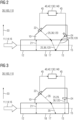
- FIG 3 a first flow sensor 10 in a second embodiment of the claimed flow measuring system 30 is shown schematically in a longitudinal section.
- FIG 3 assumes that a first step 110 of the claimed method 100 has already been completed, in which the flow measuring system 30 is provided in an active operating state.
- the first flow sensor 10 has a first ultrasonic head 22 which is aligned substantially diagonally with respect to the pipe axis 15 of the pipe 12.
- the first ultrasonic head 22 is arranged in the first flow sensor 10 such that a flow measuring pulse 35 in a diagonal direction into the pipe wall 13. When entering the pipe wall 13, the flow measurement pulse 35 is deflected.
- the flow measurement pulse 35 is part of the measuring operation of the flow measurement system 30.
- Measurement signals 45 are sent to an evaluation unit 40 for the flow measurement pulse 35.
- the first flow sensor 10 has a second ultrasonic head 24, which is arranged at a distance from the first ultrasonic head 22 in the axial direction, i.e. along the pipe axis 15.
- the second ultrasonic head 24 is located between the first ultrasonic head 22 and the FIG 3 second flow sensor 20, not shown.
- the second ultrasound head 24 is designed to send an ultrasound pulse 25 essentially in a radial direction 33 into the pipe wall 13. This takes place in a second step 120 of the claimed method 100.
- the ultrasound pulse 25 passes through the medium 11 and is reflected in an opposite area on an inner side 17 of the pipe wall 13 as an ultrasound echo 29.
- the second ultrasound head 24 is designed to also receive the ultrasound echo 29 in the second step 120.
- a deflection of the ultrasound pulse 25 when entering the pipe wall 13 and when exiting the pipe wall 13 is minimal and in FIG 3 not shown.
- the ultrasonic pulse 25 and the ultrasonic echo 29 have opposite main propagation directions 36, which FIG 3 are shown by arrows.
- the second ultrasound head 24 is suitable for measuring a signal propagation time of the ultrasound pulse 25 and the ultrasound echo 29 in conjunction with the evaluation unit 40. For this purpose, corresponding measurement signals 45 are transmitted to the evaluation unit 40.
- the evaluation unit 40 is also designed to take into account a temperature 14 of the medium 11 and an indication of the material of the medium 11 in order to determine a current speed of sound in the medium 11.
- the signal propagation time of the ultrasound pulse 25 and its ultrasound echo 29 and an installation position of the second ultrasound sensor 24 at least one pipe wall thickness 19 can be determined in a third step 130.
- the pipe inner diameter 19 can also be determined in the third step 130. This is done by a calculation in the evaluation unit 40.
- the determined pipe wall thickness 19 is stored in a fourth step 140 of the method 100 as a calibration parameter in the evaluation unit 40.
- the determined pipe wall thickness 19 or the determined pipe inner diameter 21 is taken into account when determining the throughput of medium 11 through the pipe 12.
- the essentially radial orientation of the second ultrasound head 24 generates a clear ultrasound echo 29, which allows a precise determination of the pipe wall thickness 19.
- the second ultrasound head 24 is suitable for implementing the claimed method 100 independently of the first ultrasound head 22.
- Historical values 42 for the pipe wall thickness 19 and/or the pipe inner diameter 21 are stored in the evaluation unit 40. By comparing the determined pipe wall thickness 19 and/or the determined pipe inner diameter 21 with the associated historical values 42, corrosion on the inner side 17 of the pipe wall 13 or contamination on the inner side 17 of the pipe wall 13 can be identified.
- the method 100 thus allows not only a rapid, precise calibration of the flow measuring system 30, but also a reliable diagnosis of the condition of the pipe 12.
- the operating behavior of the first flow sensor 10 can be simulated using a computer program product 50 (not shown in detail), which is designed as a digital twin of at least the first flow sensor 10.
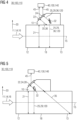
- a first flow sensor 10 according to a third embodiment of the claimed flow measuring system 30 is shown in FIG 4 shown schematically in a longitudinal section.
- the first flow sensor 10 has a first ultrasonic head 22, which is designed to emit a flow measurement pulse 35 into the medium 11 in a measuring operation.
- the flow measurement system 30 according to FIG 1 are in an active operating state, so that the first step 110 of the claimed method 100 is already completed.
- the first ultrasound head 22 is, with respect to the main propagation direction 36 of the flow measurement pulse 35, essentially aligned diagonally to the pipe axis 15.
- measurement signals 45 can be transmitted from the first ultrasound head 22 to an evaluation unit 40.
- the first flow sensor 10 also has a second ultrasound head 24, which is arranged in the region of the first ultrasound head 22.
- the second ultrasound head 24 is aligned essentially parallel to the first ultrasound head 22.
- the first flow sensor 10 has an ultrasound reflector 32, which is arranged to deflect an ultrasound pulse 25 from the second ultrasound head 24.
- the ultrasound reflector 32 is aligned such that the ultrasound pulse 25 is sent essentially along a radial direction 33 into the pipe wall 13.
- the ultrasound pulse 25 passes through the pipe wall 13 and is reflected as an ultrasound echo 29 in an area opposite the first flow sensor 10 on an inner side 17 of the pipe wall 13.
- the ultrasonic echo 29 is directed to the second ultrasonic head 24 by the ultrasonic reflector 32.
- the ultrasonic pulse 25 is transmitted and the ultrasonic echo 29 is received in a second step 120 of the claimed method 100.
- the second ultrasonic head 24 can be mounted in the first flow sensor 10 in an easily accessible manner by the ultrasonic reflector 32.
- the structure of the first flow sensor 10 is thus simplified and made cost-efficient.
- the transmission of the ultrasonic pulse 25 essentially in the radial direction 33 leads to a clear ultrasonic echo 29, which allows a particularly precise determination of a signal propagation time.
- the signal propagation time represents the duration between the transmission of the ultrasonic pulse 25 and the reception of the associated ultrasonic echo 29.
- the pipe wall thickness 19 can be determined based on the signal propagation time. The determination of the pipe wall thickness 19 takes place in a third step 130 of the claimed method 100.
- At least the determined pipe wall thickness 19 is stored as a calibration parameter in a fourth step 140 in the evaluation unit 40.
- a pipe inner diameter 21 can be determined, which can also be stored as a calibration parameter in the fourth step in the evaluation unit 40.
- historical values 42 for the pipe wall thickness 19 and/or the pipe inner diameter 21 can be stored in the evaluation unit 40.
- the embodiment shown allows the claimed method 100 for calibration to be integrated into a measuring operation.
- the first and second ultrasound heads 22, 24 can be operated in a time slice operation.
- the claimed method 100 can be easily incorporated into a continuous operation of the flow measuring system 30 (not shown in detail), so that its calibration can often be adjusted. This enables reliable, precise measuring operation.
- the operating behavior of the first flow sensor 10 can be simulated using a computer program product 50 (not shown in detail), which is designed as a digital twin of at least the first flow sensor 10.
- FIG 5 a first flow sensor 10 according to a third embodiment of the claimed flow measuring system 30 is shown schematically in a longitudinal section.
- the flow measuring system 30 is in FIG 5 already mounted on the pipe 12 and is in an active operating state.
- the first step 110 of the claimed method 100 is in FIG 5 therefore already completed.
- the first flow sensor 10 has a combined ultrasonic head 28, which comprises a first and a second ultrasonic head 22, 24.
- the first and second ultrasonic heads 22, 24 are independent of each other controllable sections of the combined ultrasound head 28.
- the first ultrasound head 22 is arranged such that, in a measuring operation, a flow measuring pulse 35 is sent essentially diagonally into the medium 11 with respect to the pipe axis 15.
- the second ultrasound head 24 arranged adjacent to the first ultrasound head 22 is designed to generate an ultrasound pulse 25 independently of the first ultrasound head 22 and thus also independently of the flow measuring pulse 35, by means of which the pipe wall thickness 19 of the pipe 12 is to be determined.
- the ultrasound pulse 25 is sent out by the second ultrasound head 24 essentially diagonally to the pipe axis 15 and is deflected essentially in a radial direction 33 by means of an ultrasound reflector 32.
- the ultrasound reflector 32 is positioned such that the flow measuring pulse 35 can pass through the ultrasound reflector 32.
- the ultrasonic pulse 25 from the second ultrasonic head 24 passes through the pipe wall 13 essentially in the radial direction 33 and is reflected as an ultrasonic echo 29 on an inner side 17 of an area of the pipe wall 13 opposite the first flow sensor 10.
- the ultrasonic echo 29 reaches the ultrasonic reflector 32, through which the ultrasonic echo 29 is directed back to the second ultrasonic head 24.
- the emission of the ultrasonic pulse 25 essentially in the radial direction 33 leads to a clear ultrasonic echo 29, which allows a particularly precise determination of a signal propagation time.
- the signal propagation time represents the duration between the emission of the ultrasonic pulse 25 and the reception of the associated ultrasonic echo 29.
- suitable measurement signals 45 can be transmitted from the combined ultrasonic head 28 to the evaluation unit 40. Taking into account a speed of sound in the material of the pipe wall 13 and an installation position of the second ultrasound head 24, the pipe wall thickness 19 can be determined based on the signal propagation time.
- the determination of the pipe wall thickness 19 takes place in a third step 130 of the claimed method 100. Furthermore, the determined pipe wall thickness 19 is stored as a calibration parameter in a fourth step 140 in the evaluation unit 40. Based on the pipe wall thickness 19 a pipe inner diameter 21 can also be determined in the third step 130, taking into account a pipe outer diameter 23. In addition, historical values 42 for the pipe wall thickness 19 and/or the pipe inner diameter 21 can be stored in the evaluation unit 40. By comparing a determined pipe wall thickness 19 and/or a determined pipe inner diameter 21 with the corresponding historical values 42, corrosion or contamination on an inner side 17 of the pipe 12 can be determined.
- the embodiment shown allows the measuring operation with the flow measurement pulse 35 and the claimed method 100 to be carried out essentially simultaneously. This allows continuous measuring operation and at the same time recalibration of the flow measurement system 30.
- the embodiment FIG 5 is therefore particularly suitable for applications in which permanent flow measurement is essential and at the same time there are special precision requirements that require essentially continuous recalibration.
- the operating behavior of the first flow sensor 10 can be simulated using a computer program product 50 (not shown in detail), which is designed as a digital twin of at least the first flow sensor 10.
- FIG 6 shows a sketch which illustrates a determination of a surface roughness in the claimed method 100 according to the functional principle.
- FIG 6 shows schematically a second ultrasound head 24 which, during the second step 120 of the method 100, sends an ultrasound pulse 25 diagonally to an opposite area on an inner side 17 of the pipe wall 13.
- the opposite area of the pipe wall 13 has a surface roughness 27 which is representative of the inner side 17 of the pipe wall 13.
- the surface roughness 27 on the inner side 17 causes the ultrasound pulse 25 as a plurality of ultrasonic echoes 29 reflected in different directions.
- An intensity of the ultrasonic echo 29 which is reflected back to the second ultrasonic head 24 is reduced compared to an intensity of the ultrasonic pulse 25.
- the surface roughness 27 can be quantitatively recorded, in particular taking into account information about the material of the pipe wall 13. For this purpose, a relationship is formed between the intensity of the emitted ultrasonic pulse 25 and the received ultrasonic echo 29.
- the determined surface roughness 27 can be stored as a calibration parameter in the evaluation unit 40.
- the surface roughness 27 can be used for a measuring operation of the flow measuring system 30 (not shown in detail), in particular in the Hagen-Poiseuille equation. Alternatively or additionally, the determined surface roughness 27 can also be used to quantify the progress of corrosion of the inner side 17 of the pipe wall 13.
- the reflection behavior of the pipe wall 13 as a function of the surface roughness 27 is part of an operating behavior of the flow sensor 10, which can be simulated by a computer program product 50.
- the computer program product 50 is designed as a digital twin, by means of which at least the opposite pipe wall 18 can be adjusted in terms of surface roughness 27.
Landscapes
- Physics & Mathematics (AREA)
- Fluid Mechanics (AREA)
- General Physics & Mathematics (AREA)
- Electromagnetism (AREA)
- Measuring Volume Flow (AREA)
Claims (11)
- Procédé (100) d'étalonnage d'un système (30) de mesure du débit, qui est monté sur un tuyau (12), entourant un milieu (11), comprenant les stades :a) on se procure le système (30) de mesure du débit, qui comprend un premier capteur (10) du débit, dans un état de fonctionnement actif ;b) envoi d'une impulsion (25) d'ultrasons dans une paroi (13) du tuyau (12) au moyen d'une première ou d'une deuxième tête (22, 24) d'ultrasons du premier capteur (10) du débit et réception d'un écho (29) d'ultrasons au moyen de la deuxième tête (24) d'ultrasons ;c) détermination du temps de propagation du signal de l'impulsion (25) d'ultrasons et de l'écho (29) d'ultrasons et détermination d'une épaisseur (19) de la paroi du tuyau à l'aide du temps de propagation du signal ;d) établissement de paramètres d'étalonnage du premier capteur (30) du débit, dans lequel les paramètres d'étalonnage comprennent l'épaisseur (19) de la paroi du tuyau,caractérisé en ce que, dans le stade b) pour une détermination d'une rugosité (27) de surface d'une face (17) intérieure de la paroi (13) du tuyau, on envoie l'impulsion (25) d'ultrasons dans une direction en diagonale dans le milieu (11), et on détecte une intensité de l'écho (29) d'ultrasons reçue et on la compare à une intensité de l'impulsion (25) d'ultrasons envoyée, dans lequel, sur cette base, on détermine la rugosité (27) de surface de la face (17) intérieure de la paroi (13) du tuyau, et on établit également, comme paramètres d'étalonnage, la rugosité (27) de surface déterminée de la face (17) intérieure de la paroi (13) du tuyau dans le stade d).
- Procédé (100) suivant la revendication 1, caractérisé en ce que l'on associe, à la deuxième tête (24) d'ultrasons du premier capteur (10) du débit, un réflecteur (32) d'ultrasons pour une déviation de l'impulsion (25) d'ultrasons.
- Procédé (100) suivant l'une des revendications 1 ou 2, caractérisé en ce que la première tête (22) d'ultrasons est constituée pour l'émission d'une impulsion (35) de mesure du débit.
- Procédé (100) suivant la revendication 3, caractérisé en ce que l'on fait la différence entre l'impulsion (25) d'ultrasons dans le stade b) et l'impulsion (35) de mesure du débit par un filtre électronique, en particulier un filtre passe bande.
- Procédé (100) suivant l'une des revendications 3 ou 4, caractérisé en ce que l'impulsion (25) d'ultrasons suivant le stade b) et l'impulsion (35) de mesure du débit sont constituées de manière à pouvoir être différenciées par émission décalée dans le temps.
- Procédé (100) suivant l'une des revendications 1 à 5, caractérisé en ce que l'impulsion (25) d'ultrasons dans le stade b) a une largeur de bande de 25 kHz à 8 MHz et/ou une durée d'impulsion de 0,1 µs à 5,0 ms.
- Procédé (100) suivant l'une des revendications 1 à 6, caractérisé en ce que le stade c) s'effectue aussi à l'aide d'une indication sur un matériau de la paroi (13) du tuyau et/ou à l'aide d'une indication sur une jonction du premier capteur (10) du débit au tuyau (12).
- Procédé (100) suivant l'une des revendications 1 à 7, caractérisé en ce que, à l'aide de l'épaisseur (19) de paroi du tuyau déterminée au stade c), on détermine une corrosion du tuyau (12) ou une souillure du tuyau (12).
- Système (30) de mesure du débit, comprenant un premier et un deuxième capteurs (10, 20) du débit, dans lequel le premier capteur (10) du débit est constitué pour l'envoi d'une impulsion (35) de mesure du débit au moyen d'une première tête (22) d'ultrasons et le deuxième capteur (20) du débit pour la réception d'un écho (37) de l'impulsion (35) de mesure du débit, dans lequel le premier capteur (10) du débit a une deuxième tête (24) d'ultrasons pour la détermination d'une épaisseur (19) de la paroi du tuyau, dans lequel le système (30) de mesure du débit a une unité (40) d'évaluation, qui est constituée pour la réception et l'évaluation de signaux (45) de mesure du premier capteur (10) de débit, caractérisé en ce que l'unité (40) d'évaluation est constituée pour effectuer un étalonnage moyen d'un procédé (100) suivant l'une des revendications 1 à 8.
- Système (30) de mesure du débit suivant la revendication 9, caractérisé en ce que l'unité (40) d'évaluation est constituée sous la forme d'une unité d'évaluation locale, qui est reçue dans l'un des capteurs (10, 20) du débit ou est constituée en commande industrielle.
- Produit (50) de programme d'ordinateur, qui comprend des instructions, qui font qu'un ordinateur simule le comportement de fonctionnement d'un système (30) de mesure du débit monté sur un tuyau (12), caractérisé en ce que le système (30) de mesure du débit est constitué suivant la revendication 9 ou 10, dans lequel le produit (50) de programme d'ordinateur est constitué en double numérique et est constitué pour contrôler la vraisemblance des temps de propagation du signal détecté des têtes (22, 24) d'ultrasons du système (30) de mesure du débit ou d'autres valeurs de capteur d'une installation, dans laquelle le système (30) de mesure du débit est utilisé.
Applications Claiming Priority (2)
| Application Number | Priority Date | Filing Date | Title |
|---|---|---|---|
| DE102021211941.7A DE102021211941A1 (de) | 2021-10-22 | 2021-10-22 | Kalibrierverfahren für ein Durchflussmesssystem, Durchflussmesssystem und Computerprogrammprodukt |
| PCT/EP2022/076399 WO2023066594A1 (fr) | 2021-10-22 | 2022-09-22 | Procédé d'étalonnage pour système de mesure de débit, système de mesure de débit et produit programme d'ordinateur |
Publications (3)
| Publication Number | Publication Date |
|---|---|
| EP4367484A1 EP4367484A1 (fr) | 2024-05-15 |
| EP4367484B1 true EP4367484B1 (fr) | 2025-01-29 |
| EP4367484C0 EP4367484C0 (fr) | 2025-01-29 |
Family
ID=83689351
Family Applications (1)
| Application Number | Title | Priority Date | Filing Date |
|---|---|---|---|
| EP22786804.9A Active EP4367484B1 (fr) | 2021-10-22 | 2022-09-22 | Procédé d'étalonnage pour système de mesure de débit, système de mesure de débit et produit programme d'ordinateur |
Country Status (6)
| Country | Link |
|---|---|
| US (1) | US12209898B2 (fr) |
| EP (1) | EP4367484B1 (fr) |
| CN (1) | CN118159807B (fr) |
| AU (1) | AU2022368950B2 (fr) |
| DE (1) | DE102021211941A1 (fr) |
| WO (1) | WO2023066594A1 (fr) |
Families Citing this family (4)
| Publication number | Priority date | Publication date | Assignee | Title |
|---|---|---|---|---|
| KR20230009411A (ko) * | 2020-05-11 | 2023-01-17 | 켄웨이브 솔루션스 인크. | 압력 용기들의 성질들의 비침습적 판단을 위한 시스템들 및 방법들 |
| CN119023012B (zh) * | 2024-07-24 | 2025-11-28 | 杭州炬源智能科技有限公司 | 基于磁感应脉冲与超声波双采样的水表计量方法与系统 |
| DE102024121074A1 (de) * | 2024-07-24 | 2026-01-29 | Sensaru GmbH | Ultraschall-Durchflussmessvorrichtung |
| CN119779213B (zh) * | 2025-01-10 | 2025-07-18 | 四川大学 | 一种粗糙壁面构件超声信号时空自适应交叉相关测量方法 |
Family Cites Families (16)
| Publication number | Priority date | Publication date | Assignee | Title |
|---|---|---|---|---|
| GB8710064D0 (en) | 1987-04-28 | 1987-06-03 | Micronics Ltd | Ultrasonic fluid flowmeter |
| WO1995017650A1 (fr) | 1993-12-23 | 1995-06-29 | Endress + Hauser Flowtec Ag | Appareil verrouillable de mesure par ultrasons du debit volumique |
| DE102007019689A1 (de) * | 2007-04-24 | 2008-10-30 | Endress + Hauser Flowtec Ag | Vorrichtung zur Bestimmung und/oder Überwachung des Volumen- und/oder Massedurchflusses eines Mediums |
| DE102007062913A1 (de) | 2007-12-21 | 2009-06-25 | Endress + Hauser Flowtec Ag | Ultraschallwandler zur Bestimmung und/oder Überwachung eines Durchflusses eines Messmediums durch ein Messrohr |
| JP5641491B2 (ja) * | 2008-10-24 | 2014-12-17 | 横河電機株式会社 | 超音波流量計 |
| DE102009002942A1 (de) | 2009-05-08 | 2010-11-11 | Endress + Hauser Flowtec Ag | Verfahren zum Bestimmen einer Messrohr-Rohrwanddicke eines Coriolis-Durchflussmessgerätes |
| US8626466B2 (en) * | 2010-02-11 | 2014-01-07 | Daniel Measurement And Control, Inc. | Flow meter validation |
| US9383476B2 (en) * | 2012-07-09 | 2016-07-05 | Weatherford Technology Holdings, Llc | In-well full-bore multiphase flowmeter for horizontal wellbores |
| DE102015107752A1 (de) | 2015-05-18 | 2016-11-24 | Endress + Hauser Flowtec Ag | Verfahren zur Ermittlung zumindest einer Rohrwandresonanzfrequenz sowie Clamp-On-Ultraschall-Durchflussmessgerät |
| KR101622543B1 (ko) | 2015-11-27 | 2016-05-19 | 자인테크놀로지(주) | 파이프 두께 자동 측정 기능을 구비하는 외벽 부착식 초음파 유량계 |
| US20170286572A1 (en) | 2016-03-31 | 2017-10-05 | General Electric Company | Digital twin of twinned physical system |
| JP7010770B2 (ja) * | 2018-06-13 | 2022-01-26 | 日立Geニュークリア・エナジー株式会社 | 超音波検査システム |
| US11624639B2 (en) | 2019-04-09 | 2023-04-11 | Dune Labs Inc. | Ultrasonic flow metering |
| CN112067066A (zh) * | 2020-09-16 | 2020-12-11 | 杭州乾博科技有限公司 | 一种可校正的超声波流量计 |
| CN112254791B (zh) * | 2020-10-16 | 2022-06-07 | 中国计量科学研究院 | 一种基于静水拖曳的超声时间溯源方法 |
| CN113237516A (zh) * | 2021-06-03 | 2021-08-10 | 中北大学 | 一种智能化超声波测量系统及测量方法 |
-
2021
- 2021-10-22 DE DE102021211941.7A patent/DE102021211941A1/de active Pending
-
2022
- 2022-09-22 US US18/702,585 patent/US12209898B2/en active Active
- 2022-09-22 WO PCT/EP2022/076399 patent/WO2023066594A1/fr not_active Ceased
- 2022-09-22 CN CN202280070769.3A patent/CN118159807B/zh active Active
- 2022-09-22 AU AU2022368950A patent/AU2022368950B2/en active Active
- 2022-09-22 EP EP22786804.9A patent/EP4367484B1/fr active Active
Also Published As
| Publication number | Publication date |
|---|---|
| CN118159807B (zh) | 2025-08-15 |
| US12209898B2 (en) | 2025-01-28 |
| AU2022368950B2 (en) | 2025-03-06 |
| EP4367484A1 (fr) | 2024-05-15 |
| DE102021211941A1 (de) | 2023-04-27 |
| CN118159807A (zh) | 2024-06-07 |
| US20240418560A1 (en) | 2024-12-19 |
| AU2022368950A1 (en) | 2024-03-14 |
| WO2023066594A1 (fr) | 2023-04-27 |
| EP4367484C0 (fr) | 2025-01-29 |
Similar Documents
| Publication | Publication Date | Title |
|---|---|---|
| EP4367484B1 (fr) | Procédé d'étalonnage pour système de mesure de débit, système de mesure de débit et produit programme d'ordinateur | |
| DE3751714T2 (de) | Verfahren und Apparatur zum Ultraschallnachweis von Rissen | |
| EP2335064B1 (fr) | Méthode par impulsion-écho au moyen d'un réseau de transducteurs et avec compensation thermique | |
| DE3319068C2 (fr) | ||
| DE102009047317A1 (de) | Verfahren und Vorrichtung zur Ultraschallprüfung | |
| EP2992321B1 (fr) | Procédé et dispositif pour l'evaluation des defauts par saft (synthetic aperture focussing technique) | |
| EP1764589B1 (fr) | Procédé pour le contrôle d'un débitmètre massique à effet Coriolis | |
| DE102009047318A1 (de) | Vorrichtung und Verfahren zur Ultraschalluntersuchung | |
| EP2335063B1 (fr) | Méthode par impulsion-écho avec détermination de la géométrie de la ligne à retard | |
| EP3857185B1 (fr) | Procédé et dispositif pour la mesure acoustique dans un tuyau | |
| EP3894799B1 (fr) | Agencement de transducteurs ultrasonores d'un appareil de mesure de debit a ultrasons a pinces, et appareil de mesure de debit a ultrasons a pinces et procede de mise en marche de l'appareil de mesure de debit a ultrasons a pinces | |
| DE2613799C2 (de) | Verfahren zum Einrichten von Ultraschall-Prüfanlagen | |
| WO2014009165A1 (fr) | Procédé et dispositif de détermination de la hauteur d'un niveau de fluide dans un réservoir de fluide | |
| AT520557B1 (de) | Verfahren zur Ermittlung eines korrigierten Werts für die viskositätsabhängige Schallgeschwindigkeit in einem zu untersuchenden Fluid | |
| DE102023113539A1 (de) | Ultraschall-Durchflussmessvorrichtung zum Bestimmen eines Durchflusses eines fluiden Mediums durch eine Rohrleitung | |
| WO2007012332A1 (fr) | Procede de verification non destructive de tuyaux, pour detecter d'eventuels defauts superficiels | |
| DE102012112120B4 (de) | Verfahren und Vorrichtung zur oberflächennahen zerstörungsfreien Prüfung eines rotationssymmetrischen Werkstücks mit abschnittsweise wechselndem Durchmesser mittels Ultraschall | |
| DE3412615C2 (de) | Verfahren zur Korngrößenbestimmung in einem polykristallinen Werkstoff | |
| DE10354473B4 (de) | Mehrkanalige Ultraschall-Messeinrichtung | |
| DE10258336B3 (de) | Verfahren und Vorrichtung zur zerstörungsfreien Werkstoffprüfung mittels Ultraschall | |
| EP1283412A2 (fr) | Procédé et dispositif de détection d'une opération de remplissage | |
| DE102018119206A1 (de) | Verfahren zum Erfassen der Geometrie eines Bereichs eines Gegenstandes mittels Ultraschall | |
| EP3629058B1 (fr) | Procédé de mise en uvre d'un diagnostic ou d'un essai automatique dans un système de mesure par ultrasons | |
| EP3480436B1 (fr) | Procédé et dispositif d'analyse du comportement acoustique d'un clapet de gaz d'échappement | |
| EP3781938B1 (fr) | Dispositif et procédé de détermination de l'extension d'endroits défectueux par sondage acoustique v |
Legal Events
| Date | Code | Title | Description |
|---|---|---|---|
| STAA | Information on the status of an ep patent application or granted ep patent |
Free format text: STATUS: UNKNOWN |
|
| STAA | Information on the status of an ep patent application or granted ep patent |
Free format text: STATUS: THE INTERNATIONAL PUBLICATION HAS BEEN MADE |
|
| PUAI | Public reference made under article 153(3) epc to a published international application that has entered the european phase |
Free format text: ORIGINAL CODE: 0009012 |
|
| STAA | Information on the status of an ep patent application or granted ep patent |
Free format text: STATUS: REQUEST FOR EXAMINATION WAS MADE |
|
| 17P | Request for examination filed |
Effective date: 20240205 |
|
| AK | Designated contracting states |
Kind code of ref document: A1 Designated state(s): AL AT BE BG CH CY CZ DE DK EE ES FI FR GB GR HR HU IE IS IT LI LT LU LV MC MK MT NL NO PL PT RO RS SE SI SK SM TR |
|
| GRAP | Despatch of communication of intention to grant a patent |
Free format text: ORIGINAL CODE: EPIDOSNIGR1 |
|
| STAA | Information on the status of an ep patent application or granted ep patent |
Free format text: STATUS: GRANT OF PATENT IS INTENDED |
|
| DAV | Request for validation of the european patent (deleted) | ||
| DAX | Request for extension of the european patent (deleted) | ||
| INTG | Intention to grant announced |
Effective date: 20240925 |
|
| GRAS | Grant fee paid |
Free format text: ORIGINAL CODE: EPIDOSNIGR3 |
|
| GRAA | (expected) grant |
Free format text: ORIGINAL CODE: 0009210 |
|
| STAA | Information on the status of an ep patent application or granted ep patent |
Free format text: STATUS: THE PATENT HAS BEEN GRANTED |
|
| AK | Designated contracting states |
Kind code of ref document: B1 Designated state(s): AL AT BE BG CH CY CZ DE DK EE ES FI FR GB GR HR HU IE IS IT LI LT LU LV MC MK MT NL NO PL PT RO RS SE SI SK SM TR |
|
| REG | Reference to a national code |
Ref country code: GB Ref legal event code: FG4D Free format text: NOT ENGLISH |
|
| REG | Reference to a national code |
Ref country code: CH Ref legal event code: EP |
|
| REG | Reference to a national code |
Ref country code: DE Ref legal event code: R096 Ref document number: 502022002821 Country of ref document: DE |
|
| REG | Reference to a national code |
Ref country code: IE Ref legal event code: FG4D Free format text: LANGUAGE OF EP DOCUMENT: GERMAN |
|
| U01 | Request for unitary effect filed |
Effective date: 20250129 |
|
| U07 | Unitary effect registered |
Designated state(s): AT BE BG DE DK EE FI FR IT LT LU LV MT NL PT RO SE SI Effective date: 20250204 |
|
| PG25 | Lapsed in a contracting state [announced via postgrant information from national office to epo] |
Ref country code: RS Free format text: LAPSE BECAUSE OF FAILURE TO SUBMIT A TRANSLATION OF THE DESCRIPTION OR TO PAY THE FEE WITHIN THE PRESCRIBED TIME-LIMIT Effective date: 20250429 |
|
| PG25 | Lapsed in a contracting state [announced via postgrant information from national office to epo] |
Ref country code: PL Free format text: LAPSE BECAUSE OF FAILURE TO SUBMIT A TRANSLATION OF THE DESCRIPTION OR TO PAY THE FEE WITHIN THE PRESCRIBED TIME-LIMIT Effective date: 20250129 |
|
| PG25 | Lapsed in a contracting state [announced via postgrant information from national office to epo] |
Ref country code: ES Free format text: LAPSE BECAUSE OF FAILURE TO SUBMIT A TRANSLATION OF THE DESCRIPTION OR TO PAY THE FEE WITHIN THE PRESCRIBED TIME-LIMIT Effective date: 20250129 |
|
| PG25 | Lapsed in a contracting state [announced via postgrant information from national office to epo] |
Ref country code: NO Free format text: LAPSE BECAUSE OF FAILURE TO SUBMIT A TRANSLATION OF THE DESCRIPTION OR TO PAY THE FEE WITHIN THE PRESCRIBED TIME-LIMIT Effective date: 20250429 Ref country code: IS Free format text: LAPSE BECAUSE OF FAILURE TO SUBMIT A TRANSLATION OF THE DESCRIPTION OR TO PAY THE FEE WITHIN THE PRESCRIBED TIME-LIMIT Effective date: 20250529 |
|
| PG25 | Lapsed in a contracting state [announced via postgrant information from national office to epo] |
Ref country code: HR Free format text: LAPSE BECAUSE OF FAILURE TO SUBMIT A TRANSLATION OF THE DESCRIPTION OR TO PAY THE FEE WITHIN THE PRESCRIBED TIME-LIMIT Effective date: 20250129 |
|
| PG25 | Lapsed in a contracting state [announced via postgrant information from national office to epo] |
Ref country code: GR Free format text: LAPSE BECAUSE OF FAILURE TO SUBMIT A TRANSLATION OF THE DESCRIPTION OR TO PAY THE FEE WITHIN THE PRESCRIBED TIME-LIMIT Effective date: 20250430 |
|
| PG25 | Lapsed in a contracting state [announced via postgrant information from national office to epo] |
Ref country code: SM Free format text: LAPSE BECAUSE OF FAILURE TO SUBMIT A TRANSLATION OF THE DESCRIPTION OR TO PAY THE FEE WITHIN THE PRESCRIBED TIME-LIMIT Effective date: 20250129 |
|
| PG25 | Lapsed in a contracting state [announced via postgrant information from national office to epo] |
Ref country code: CZ Free format text: LAPSE BECAUSE OF FAILURE TO SUBMIT A TRANSLATION OF THE DESCRIPTION OR TO PAY THE FEE WITHIN THE PRESCRIBED TIME-LIMIT Effective date: 20250129 |
|
| PG25 | Lapsed in a contracting state [announced via postgrant information from national office to epo] |
Ref country code: SK Free format text: LAPSE BECAUSE OF FAILURE TO SUBMIT A TRANSLATION OF THE DESCRIPTION OR TO PAY THE FEE WITHIN THE PRESCRIBED TIME-LIMIT Effective date: 20250129 |
|
| U20 | Renewal fee for the european patent with unitary effect paid |
Year of fee payment: 4 Effective date: 20250919 |
|
| PLBE | No opposition filed within time limit |
Free format text: ORIGINAL CODE: 0009261 |
|
| STAA | Information on the status of an ep patent application or granted ep patent |
Free format text: STATUS: NO OPPOSITION FILED WITHIN TIME LIMIT |
|
| REG | Reference to a national code |
Ref country code: CH Ref legal event code: L10 Free format text: ST27 STATUS EVENT CODE: U-0-0-L10-L00 (AS PROVIDED BY THE NATIONAL OFFICE) Effective date: 20251210 |
|
| 26N | No opposition filed |
Effective date: 20251030 |
|
| REG | Reference to a national code |
Ref country code: CH Ref legal event code: H13 Free format text: ST27 STATUS EVENT CODE: U-0-0-H10-H13 (AS PROVIDED BY THE NATIONAL OFFICE) Effective date: 20260425 |