EP4367497B1 - Messkammererweiterung zur spektrophotometrischen charakterisierung einer sterilen flüssigkeit in einem polymerbehälter mittels nir- oder raman-spektrophotometrie - Google Patents
Messkammererweiterung zur spektrophotometrischen charakterisierung einer sterilen flüssigkeit in einem polymerbehälter mittels nir- oder raman-spektrophotometrie Download PDFInfo
- Publication number
- EP4367497B1 EP4367497B1 EP21745705.0A EP21745705A EP4367497B1 EP 4367497 B1 EP4367497 B1 EP 4367497B1 EP 21745705 A EP21745705 A EP 21745705A EP 4367497 B1 EP4367497 B1 EP 4367497B1
- Authority
- EP
- European Patent Office
- Prior art keywords
- spectrophotometer
- mirror
- light
- measurement chamber
- nir
- Prior art date
- Legal status (The legal status is an assumption and is not a legal conclusion. Google has not performed a legal analysis and makes no representation as to the accuracy of the status listed.)
- Active
Links
Images


Classifications
-
- G—PHYSICS
- G01—MEASURING; TESTING
- G01N—INVESTIGATING OR ANALYSING MATERIALS BY DETERMINING THEIR CHEMICAL OR PHYSICAL PROPERTIES
- G01N15/00—Investigating characteristics of particles; Investigating permeability, pore-volume or surface-area of porous materials
- G01N15/02—Investigating particle size or size distribution
- G01N15/0205—Investigating particle size or size distribution by optical means
-
- G—PHYSICS
- G01—MEASURING; TESTING
- G01N—INVESTIGATING OR ANALYSING MATERIALS BY DETERMINING THEIR CHEMICAL OR PHYSICAL PROPERTIES
- G01N15/00—Investigating characteristics of particles; Investigating permeability, pore-volume or surface-area of porous materials
- G01N15/06—Investigating concentration of particle suspensions
- G01N15/075—Investigating concentration of particle suspensions by optical means
-
- G—PHYSICS
- G01—MEASURING; TESTING
- G01N—INVESTIGATING OR ANALYSING MATERIALS BY DETERMINING THEIR CHEMICAL OR PHYSICAL PROPERTIES
- G01N21/00—Investigating or analysing materials by the use of optical means, i.e. using sub-millimetre waves, infrared, visible or ultraviolet light
- G01N21/01—Arrangements or apparatus for facilitating the optical investigation
- G01N21/03—Cuvette constructions
- G01N21/0303—Optical path conditioning in cuvettes, e.g. windows; adapted optical elements or systems; path modifying or adjustment
-
- G—PHYSICS
- G01—MEASURING; TESTING
- G01N—INVESTIGATING OR ANALYSING MATERIALS BY DETERMINING THEIR CHEMICAL OR PHYSICAL PROPERTIES
- G01N21/00—Investigating or analysing materials by the use of optical means, i.e. using sub-millimetre waves, infrared, visible or ultraviolet light
- G01N21/17—Systems in which incident light is modified in accordance with the properties of the material investigated
- G01N21/25—Colour; Spectral properties, i.e. comparison of effect of material on the light at two or more different wavelengths or wavelength bands
- G01N21/31—Investigating relative effect of material at wavelengths characteristic of specific elements or molecules, e.g. atomic absorption spectrometry
- G01N21/35—Investigating relative effect of material at wavelengths characteristic of specific elements or molecules, e.g. atomic absorption spectrometry using infrared light
- G01N21/3577—Investigating relative effect of material at wavelengths characteristic of specific elements or molecules, e.g. atomic absorption spectrometry using infrared light for analysing liquids, e.g. polluted water
-
- G—PHYSICS
- G01—MEASURING; TESTING
- G01N—INVESTIGATING OR ANALYSING MATERIALS BY DETERMINING THEIR CHEMICAL OR PHYSICAL PROPERTIES
- G01N21/00—Investigating or analysing materials by the use of optical means, i.e. using sub-millimetre waves, infrared, visible or ultraviolet light
- G01N21/17—Systems in which incident light is modified in accordance with the properties of the material investigated
- G01N21/25—Colour; Spectral properties, i.e. comparison of effect of material on the light at two or more different wavelengths or wavelength bands
- G01N21/31—Investigating relative effect of material at wavelengths characteristic of specific elements or molecules, e.g. atomic absorption spectrometry
- G01N21/35—Investigating relative effect of material at wavelengths characteristic of specific elements or molecules, e.g. atomic absorption spectrometry using infrared light
- G01N21/359—Investigating relative effect of material at wavelengths characteristic of specific elements or molecules, e.g. atomic absorption spectrometry using infrared light using near infrared light
-
- G—PHYSICS
- G01—MEASURING; TESTING
- G01N—INVESTIGATING OR ANALYSING MATERIALS BY DETERMINING THEIR CHEMICAL OR PHYSICAL PROPERTIES
- G01N21/00—Investigating or analysing materials by the use of optical means, i.e. using sub-millimetre waves, infrared, visible or ultraviolet light
- G01N21/62—Systems in which the material investigated is excited whereby it emits light or causes a change in wavelength of the incident light
- G01N21/63—Systems in which the material investigated is excited whereby it emits light or causes a change in wavelength of the incident light optically excited
- G01N21/65—Raman scattering
-
- G—PHYSICS
- G01—MEASURING; TESTING
- G01N—INVESTIGATING OR ANALYSING MATERIALS BY DETERMINING THEIR CHEMICAL OR PHYSICAL PROPERTIES
- G01N21/00—Investigating or analysing materials by the use of optical means, i.e. using sub-millimetre waves, infrared, visible or ultraviolet light
- G01N21/84—Systems specially adapted for particular applications
- G01N21/88—Investigating the presence of flaws or contamination
- G01N21/94—Investigating contamination, e.g. dust
-
- G—PHYSICS
- G01—MEASURING; TESTING
- G01N—INVESTIGATING OR ANALYSING MATERIALS BY DETERMINING THEIR CHEMICAL OR PHYSICAL PROPERTIES
- G01N15/00—Investigating characteristics of particles; Investigating permeability, pore-volume or surface-area of porous materials
- G01N2015/0092—Monitoring flocculation or agglomeration
-
- G—PHYSICS
- G01—MEASURING; TESTING
- G01N—INVESTIGATING OR ANALYSING MATERIALS BY DETERMINING THEIR CHEMICAL OR PHYSICAL PROPERTIES
- G01N15/00—Investigating characteristics of particles; Investigating permeability, pore-volume or surface-area of porous materials
- G01N15/06—Investigating concentration of particle suspensions
- G01N2015/0687—Investigating concentration of particle suspensions in solutions, e.g. non volatile residue
-
- G—PHYSICS
- G01—MEASURING; TESTING
- G01N—INVESTIGATING OR ANALYSING MATERIALS BY DETERMINING THEIR CHEMICAL OR PHYSICAL PROPERTIES
- G01N21/00—Investigating or analysing materials by the use of optical means, i.e. using sub-millimetre waves, infrared, visible or ultraviolet light
- G01N21/62—Systems in which the material investigated is excited whereby it emits light or causes a change in wavelength of the incident light
- G01N21/63—Systems in which the material investigated is excited whereby it emits light or causes a change in wavelength of the incident light optically excited
- G01N21/65—Raman scattering
- G01N2021/651—Cuvettes therefore
-
- G—PHYSICS
- G01—MEASURING; TESTING
- G01N—INVESTIGATING OR ANALYSING MATERIALS BY DETERMINING THEIR CHEMICAL OR PHYSICAL PROPERTIES
- G01N2201/00—Features of devices classified in G01N21/00
- G01N2201/02—Mechanical
- G01N2201/024—Modular construction
- G01N2201/0245—Modular construction with insertable-removable part
-
- G—PHYSICS
- G01—MEASURING; TESTING
- G01N—INVESTIGATING OR ANALYSING MATERIALS BY DETERMINING THEIR CHEMICAL OR PHYSICAL PROPERTIES
- G01N2201/00—Features of devices classified in G01N21/00
- G01N2201/06—Illumination; Optics
- G01N2201/063—Illuminating optical parts
- G01N2201/0636—Reflectors
-
- G—PHYSICS
- G01—MEASURING; TESTING
- G01N—INVESTIGATING OR ANALYSING MATERIALS BY DETERMINING THEIR CHEMICAL OR PHYSICAL PROPERTIES
- G01N2201/00—Features of devices classified in G01N21/00
- G01N2201/06—Illumination; Optics
- G01N2201/064—Stray light conditioning
-
- G—PHYSICS
- G01—MEASURING; TESTING
- G01N—INVESTIGATING OR ANALYSING MATERIALS BY DETERMINING THEIR CHEMICAL OR PHYSICAL PROPERTIES
- G01N2201/00—Features of devices classified in G01N21/00
- G01N2201/08—Optical fibres; light guides
Definitions
- the present invention relates to the identification and/or quantification of an active pharmaceutical ingredient (API), an excipient and a possible adulterant and/or contaminant thereof, as well as the quantification/detection/verification of physical properties (agglomeration, particle size etc.) of such medicinal product in liquid state in a sterile package, particularly in an infusion bag or in a syringe within a sterile package.
- API active pharmaceutical ingredient
- quality and/or identity control of pharmaceutical products immediately before their application is of utmost importance.
- quality and/or identity control can, for example, be done by evaluating spectroscopic measurements of the pharmaceutical product which is often present as a sterile solution in a polymer container, e.g. an infusion bag or a disposable syringe which is held inside a sterile package.
- a sample of a batch of the pharmaceutical product is taken and analysed resulting in the destruction of the sample/batch.
- n 1
- n 1
- those approaches often require an analytical laboratory as well as trained, highly specialized personnel to evaluate analysis results, e. g. spectra or chromatograms.
- US 2011/021890 A1 discloses a measurement chamber extension for a spectrophotometric characterization with an IR photometer;
- AU 2016 206 289 A1 discloses a perspective view of a docking station or sleeve adapted to receive a syringe, and
- US 2010/309468 A1 discloses a container holder comprising a clamp.
- a transmission or a transflection of a measuring light beam (sample beam) of a NIR-spectrophotometer or a Raman-spectrophotometer which is directed through the polymer container comprising the pharmaceutically active substance in dissolved state or as a suspension or an emulsion, whether in an infusion bag or in a syringe within a sterile package and, optionally, backwards - by measuring in transflection - the gathered information can be used to identify or even quantify chemical components in the liquid.
- the used measurement principles can be based upon transflection (light path through the package and backwards) or transmission (sample beam passes only once through the package (liquid)).
- the best area for measurements is defined.
- the optimal parameters for this area are as follows:
- the NIR or Raman instrument, the (optional) sterile package of the sample, as well as the optical element are positioned such as to ensure one or more of the above-mentioned conditions.
- a syringe or an infusion bag For positioning of, e.g., a syringe or an infusion bag to be measured, different types of holders or combinations of these can be used.
- These holders are individually manufactured depending on the particular type of syringe and thus the required optimal position of the corresponding package holder.
- a holder for infusion bags for each product line of each producer is typically easier to design and hence, rather universal.
- the invention describes the identification, the quantification and discrimination of using NIR-spectral and Raman-spectral characteristics of package material (plastic bag or syringe and syringe packaging), solvent and pharmaceutically active ingredient as well as unwanted solutes (adulterants and/or contaminants).
- an erroneous misfiling as well as a contamination or illicit substitution of a pharmaceutical solution by an adulterant can be identified. Even a correct concentration of a given substance within the bag or syringe can be detected.
- a semi-solid as used herein, comprises a gel, a paste or a lotion (of higher viscosity in comparison to usual physiological (aqueous) solutions and therefore mostly a two-phased-system, solid/liquid or liquid/liquid).
- the term is used in correspondence to its common understanding by the skilled person in pharmaceutical technology and/or food technology.
- liquid compositions which can be measured using the suggested measurement chamber extension may comprise solutions and dispersions, for example, consist of a multicomponent/multiphase system.
- a measurement chamber according to the invention is defined in independent claim 1.
- the comparison of the collected new NIR-spectrum with known and alternatively analyzed NIR-spectra of the same sample type allow qualitative and at least semiquantitative detection of chemical substances and/or physical properties of the sample dissolved or suspended in the liquid inside the container.
- known and alternatively analyzed NIR-spectra of the same sample type packetaging, excipient, API
- the container holder comprises a support structure for the optical element, wherein the support structure comprises a channel, wherein a width of the channel is adapted to fit with a width of the measurement window of the corresponding spectrophotometer (NIR- or Raman-spectrophotometer).
- NIR- or Raman-spectrophotometer a spectrophotometer
- the optical element comprises a mirror comprising a gold layer or at least an optical fiber or a waveguide.
- gold reflects more than 95 per cent of incident radiation at wavelengths above 700 nm. Therefore, the channel and the mirror can be coated with a gold layer or another reflective coating. Accordingly, the light measured is a transflected light.
- Said gold layer can be deposited by vacuum deposition or by plating, both galvanic and electroless; as well as by other suitable additive manufacturing techniques.
- Optical waveguides or fibers advantageously may be selected to provide a loss-free guiding, at least over the short distances which are relevant here (typically ten or a few tens of cm) for coupling from the polymer package to a photodetector or into the measuring chamber of the corresponding spectrophotometer (NIR- or Raman-spectrophotometer).
- the container holder comprises a receptacle formed by the channel together with the mirror.
- such holder is adapted to hold the container reproducibly.
- the surface of the channel is covered with a gold layer as well.
- the mirror can be made, e.g., of gold, spectralon (PTFE), or aluminum - which may provide highly reflective surfaces for light of relevant wavelength ranges (both for NIR- and Raman-spectrophotometry).
- PTFE spectralon
- aluminum - which may provide highly reflective surfaces for light of relevant wavelength ranges (both for NIR- and Raman-spectrophotometry).
- the container holder is encased by a light-tight box which comprises a lid which is adapted to close the light-tight box in a light-tight manner.
- the light guide may comprise a hollow channel or a waveguide or a bundle of waveguides.
- the light guide may comprise a lateral recess and the mirror may be placed at the distant side of the light guide, relative to the entry of the sample beam (i.e. relative to the opening, where the light guide is fitted into the box).
- the opening may even be arranged in the lid of the box.
- the optical element is fixed to the lid.
- the optical element might be arranged such on the lid as to hold the circular part of the polymer container close to the channel opening.
- the optical element may be connected to the lid by an elastic element, e.g. a spring or a spongeous material.
- an elastic element e.g. a spring or a spongeous material.
- the optical element is pressed against the polymer container, e.g. a syringe in the package. This may be used to simplify the design of the measurement chamber extension and to optimize the measurement process.
- the gold layer on the surface of the channel merges with the gold layer of the mirror and the mirror is integrated with the channel.
- the mirror together with the light guide may thus form a receptacle, i.e. the package holder.
- an orientation of the optical element, e.g. a mirror, to the light guide remains constant during all measurements which allows establishing standardized and reproducible measurement conditions.
- the optical element is a mirror, particularly, a diffusive mirror.
- the gold layer of the diffusive mirror encompasses multiple mirrors, each mirror comprising a flat polygonal face, wherein the multiple mirrors are arranged as a corrugated surface of the mirror.
- gold reflects more than 95 per cent of incident radiation at wavelengths above 700 nm.
- the corrugated structure allows complete collection even of stray light deflected within the container.
- even finely dispersed (suspended) particles may be measured.
- the multiple mirrors of the rough or smooth mirror surface can be arranged to comprise an optimized mirror or just a single smooth or rough mirror.
- the surface of these is at least partially covered by the gold layer.
- the indicated shapes i.e. the 3-dimensional structure of the rough surface allows for nearly complete diffuse reflection of the incident light, i.e. of the sample beam after its passage(s) through the package, the syringe walls and the liquid.
- the rough mirror surface comprises a roughness in a range of 20 ⁇ m - 1000 ⁇ m.
- a roughness in the range of 20 ⁇ m - 1000 ⁇ m allows for complete diffusive reflection without signal loss and thus allows for high signal/noise ratios.
- the optical element is not a mirror but a waveguide.
- waveguides typically allow for a loss-free guiding of light to and from the liquid layer within the polymer container.
- a first waveguide is positioned as to guide the measuring light from a light source of the spectrophotometer to the liquid within the polymer container and the optical element, i.e. a second waveguide.
- the second waveguide is configured to guide the measuring light after it passed through the layer of the liquid in the polymer container, the layer having a defined thickness, from the polymer container to a photodetector of the spectrophotometer.
- the polymer container which contains the liquid with the active pharmaceutical ingredient (whether a solution of the pharmaceutically active substance or a suspension/emulsion thereof) needs merely to be insulated light-tightly, e.g. be put in a light-tight box, and the two end surfaces of the first waveguide and the second waveguide (i.e. the optical element) need to be adjusted with respect to each other as to accommodate in a gap formed between the two ends a layer (having a defined thickness) of the liquid, comprising the two polymer walls of the polymer container surrounding the polymer container and the liquid itself.
- the polymer container is a disposable syringe.
- disposable syringes are made of certain well characterized polymer materials (due to the fact, that the primary and secondary packaging are thoroughly defined and only qualified suppliers can be used by the pharmaceutical manufacturer) , therefore, analysis of measurement data can be simplified.
- the light guide comprises a channel, e.g. a tube flange, wherein an end of the channel (tube flange) is shaped into a tongue which forms a receptacle, i.e. an abutment, for fitting and holding a cylinder of the syringe in an orthogonal orientation relative to a central axis of the tube flange, wherein a surface of the tongue which is oriented towards the tube flange comprises a corrugated surface comprising the mirror, and the cylinder of the syringe is arrangeable in the receptacle within a light path of the sample beam.
- a channel e.g. a tube flange
- the flange pipe (tube flange) encloses a light-guiding channel, which is also coated with a reflecting layer, e.g. a gold layer.
- the light-guiding channel ends at the corrugated mirror surface and is thus adapted to allow passage of the sample beam towards the syringe and the liquid contained therein up to the diffusive mirror, and afterwards to guide the diffusively reflected (transflected) light from the diffusive mirror to the detection unit of the NIR-spectrophotometer or Raman-spectrophotometer or through a second light-guiding channel to a transmission detector.
- the disposable syringe is enclosed by, i.e. enwrapped in, a sterile package.
- Such sterile packages typically consist of polymer foils. Their materials are known and specified by the manufacturer. Therefore, corresponding measurements can be verified using an appropriately adapted database.
- the adapter opening is adapted to accommodate a corner of an infusion bag.
- the adapter comprises a hole (channel) which may also be covered by a mirror surface or may lead in a light-guiding channel to a transmission detector.
- the adapter form can be triangular, but is always adapted individually to the shape of the infusion bag or pump of interest (comprising other forms as well).
- materials of the mirror surface may comprise, e.g., aluminum, spectralon (sintered PTFE), or gold.
- the corner of the infusion bag can be compressed (squeezed) until merely a thin layer of liquid remains. Furthermore, liquid can be completely squeezed out from this corner, in order to obtain a spectrum of the bag's polymer material alone. Thus, identification or quantification of signals which belong to the pure substance (plus solvent, excipient etc.) is facilitated.
- the mentioned before measurement chamber extension comprises an adapter with an opening which is configured for measurements of a liquid in an infusion bag which further comprises a bag orienting member, wherein an outer contour of the bag orienting member is configured to fit over a major part of an outer contour length with an inner contour of the adapter opening, if the bag orienting member is at least partially inserted into the adapter opening.
- the bag orienting member can comprise clamps to ensure an optimal, reproducible pathway. Either two separate parts above and beneath the liquid container to guide the light or one clamp comprising these both parts are possible.
- the outermost rim of the corner can be protected from ambient light, as it fits into the space formed by the opening in the adapter and the bag orienting member.
- the shorter part of the outer contour does fit with the inner contour of the opening in the base plate but allows the remainder of the bag to be held afar from the measurement path.
- corresponding pairs of permanent magnets are arranged at or near to fitting edges of the adapter opening and the bag orienting member.
- small Niobium magnets may be inserted in adjacent sections to allow self-fitting of the bag orienting member with the adapter opening. These magnets can be inserted flush with an outer surface such as to even allow light-tight fitting.
- a thickness of a layer of the liquid or of a (nano-) particle suspension in the polymer container is adjustable between 0.2 mm through 5.1 mm, preferably the layer thickness is adjustable between 0.5 mm through 2.1 mm.
- a position of the optical element can be stabilized by a fixing (or holding) member.
- a stabilization of a horizontal plane as well as a vertical stabilization and hence, a defined layer thickness can be reached.
- measurement conditions can thus be standardized.
- the holding or fixing member and the bag orienting member each comprise at least one magnet of a pair of permanent magnets for stabilization of the optical element at or within the channel, wherein the channel is dimensioned to encompass, i.e. to tightly fit, outer dimensions and shape of the optical element, e.g. a circular mirror.
- reproducibility of the measurements can be further improved.
- this allows to determine qualitatively and at least semi-quantitatively a physical or chemical parameter of the liquid or semi-solid contained in the polymer container (infusion bag or disposable syringe) and any relevant contaminant or erroneously contained foreign substance (e.g. adulterant, product of decomposition of the intended substance or the like).
- the liquid comprises a dispersion of suspended (nano-) particles
- the homogeneity of the dispersion can be evaluated.
- a quantitative determination of the active pharmaceutical ingredients a verification of the pharmaceutical quality of the product in the polymer container can be made; as well as its physical properties (e. g. particle size, presence of agglomerations, etc.) can be obtained.
- the sample beam comprises light within a wavenumber range of 4,000 cm -1 - 12,500 cm -1 .
- the spectral properties in the indicated wavelength range can be used to differentiate various pharmaceutical substances (incl. API and excipient), relevant contaminants, and physical properties (e. g. particle size, agglomeration. ..).
- repetitive measurements by different sample beams having different wavelengths are made. These sample beams are directed towards the reflective mirror under identical angles but can also be directed under different angles towards the reflective mirror. For instance, different incident angles can be selected for an identical wavelength. Different wavelengths can advantageously be directed (transflected) by the diffusive mirror under different incident angles.
- a precision of the measurements can be enhanced.
- the database used for analyzing obtained spectra comprises datasets belonging to the different sample types including typical product ranges (see also Ph. Eur. 2.2.40).
- these materials comprise organic polymers, such as e. g. PE, PP, PVC, PMMA.
- a software of the used spectrophotometer or a similar software is adapted to extract from a currently measured NIR-spectrum the information of interest (e. g. absorbance at certain wavelengths linking to a e. g. API content).
- software stored in the NIR-spectrophotometer or in the Raman-spectrophotometer or in the computerized system used to control the respective spectrophotometer, respectively is adapted to extract from a measured NIR- or Raman-spectrum the corresponding spectrum belonging to the material comprising the polymer container or the sterile package of the syringe.
- spectral data belonging to the parameter of interest can be extracted and reliably be evaluated.
- the drawing in Fig. 1 represents merely one embodiment which is adapted, e.g. for use with a commercially available spectrophotometer (e.g. a NIR- or a Raman-spectrophotometer) as offered, e.g., by Bruker or Jasco, PerkinElmer, Shimadzu, Metrohm or Varian - to name a few.
- the measurement chamber extension 10 is connected to the NIR-spectrophotometer 1 or Raman-spectrophotometer 1 using an adapter 11 which fits to the opening of the measurement chamber 20.
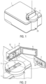
- Fig. 2 illustrates that the measurement chamber extension 10 comprises the light-tight box 9 with the open lid 8 ready for receiving a sterile package 4 containing a syringe 3' and holding it in the inner package holder 6 before connecting the measurement chamber extension 10 to the measurement chamber 20 of the NIR-spectrophotometer or Raman-spectrophotometer 1. It is shown that the light-tight box 9 is arranged just above the measurement chamber 20 to allow the measuring (sample) beam of the NIR-spectrophotometer 1 or Raman-spectrophotometer 1 (along the vertical line) to enter the light-guide 6, there shown as a light guiding channel 6 of the package holder 7.
- Fig. 3 it is illustrated how the sterile package 4 comprising the syringe is held by the internal package holder 6 just at the center of the sample beamb (red) of the light-tightly connected (via adapter 11) NIR-spectrophotometer 1 or Raman-spectrophotometer 1 (not shown).
- the box 9 of the depicted embodiment must be closed by the lid 8 in order to allow light-tight fitting of the measurement chamber extension 10 with the NIR-spectrophotometer 1 or Raman-spectrophotometer 1.
- Figure 5 is a view on the measurement chamber extension 10 from beneath, i.e. from the side of the spectrophotometer. Shown is the wall of the box 9 with the circular opening 88 for receiving the light-guide 6.
- Four slits in a circular recess 86 ensure correct position of the light-guide 6 inside the light-tight box 9 and thus, the correct orientation of the light-guide 6.
- the shape and size of the light-guide 6 can be adapted for different enclosures (packages 4) of different syringes 3.
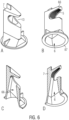
- a light-guide 6 which is there a combination of light-guide with the mirror 5 which together comprise a package holder 7.
- Fig. 6A shows the outside of said package holder 7 comprising the light guide 6 with a view into the light guide - here a channel 6.
- Fig. 6B shows a view into the light guide 6 with the mirror 5, here a diffuse mirror 5.
- the diffuse mirror 5 comprises a corrugated and rough mirroring surface.
- the tongue 66 of the light-guide 7 is adapted to hold a tubular part 3a of the sterile container 3, e.g. a syringe 3 in a sterile package 4.
- the inner surface 66 of the light guide 6 is covered with a gold layer which merges with the gold layer of the corrugated mirror 5 inside the light guide 6.
- the combined light-guide 6/package holder 7 comprises a mouth-shaped receptacle 13 or holder 13 comprising a tongue-like abutment 66.
- the inner side of the abutment 66 which is directed towards the spectrophotometer 1 comprises the corrugated mirroring surface 5.
- the corrugated structure of the mirroring surface 5 allows both diffusive reflection and secure grip of the syringe 3 which is enwrapped in the sterile package 4.
- Fig. 7 shows a view from beneath of the inner syringe holder directly into the light-guide and on the (corrugated) mirror (A), a front view (B), a side view (C) and a view from atop (D) on the light-guide 6.
- the light-guide 6 comprising the corrugated surface on the inner side of the tongue 66, i.e. the package holder, can be fabricated by injection molding, e.g. with polystyrene. It can also be fabricated from glass or, e.g., aluminum . Its surface can be coated with a gold layer, e.g. by electroless (barrel) plating or, e.g., by vapor deposition.
- Fig. 8A shows a horizontal cross-section through the light-guide 6 at the level of the mouth-shaped receptacle 7 just beneath the tongue-like abutment 66, i.e. the upper part of the sections in Figs. 8B and 8C.
- Fig. 8B is a vertical cross-section in a front-view arrangement of the light guide 6, whereas Fig. 8C is a cross-section in a side-view arrangement.
- Designation mark 66 indicates the inner surface of the light-guide 6.
- Fig. 8D shows a view on the lower part of the sections in Figs. 8B and 8C .
- the suggested measurement chamber extension 10 can be combined with every commercially available NIR-spectrophotometer 1, once its outer contour is suitably adapted to an outer contour of the measurement chamber 20 of the spectrophotometer 1.
- suitably means such adaptation which preserves the conditions of light-tightness and ensures directing the sample beam into the light-guide 6 inside the box 9 for transmission or transflection measurement of the liquid 2 within the syringe 3' in the sterile package 4.
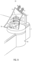
- Fig. 9 illustrates an embodiment of an extension 10 which can be combined both with a NIR-spectrophotometer 1 and a RAMAN- spectrophotometer 1.
- the infusion bag 3 is held at least at one tubular section 3a by a receptacle 13 at the container holder 7.
- An edge of the bag 3 is fitted by a bag orienting member 40 with a corresponding opening in the adapter 11.
- the adapter 11 is light-tightly connected with the measurement chamber 20 of the corresponding spectrophotometer 1.
- the measurement light beam e.g.
- NIR or a corresponding LASER beam enters the adapter 11 and arrives at (is directed to) the optical element 5 (here a mirror), which is held by a corresponding fixing member 15 (or stabilizing member 15).
- Said stabilizing member 15 ensures a direct physical contact of the optical member with the outer wall of the bag 3 (or package 4 of the syringe 3) at the corner 3b.
- the distance of the front face of the optical member with respect to the optical window of the measurement chamber 20 defines - together with the thickness of the at least two layers of polymer material - the length of the measurement light path ("layer thickness") in the liquid 2 which contains the API of interest.
- the measurement light beam is guided by a light guiding channel 6.
- the channel walls thereof are made out of a reflective material or coated with such. Suitable materials are, e.g., aluminum, gold, spectralon, to name a few.
- the mirror i.e. its three-dimensional shape, fitting contour 41 and the surface structure, i.e. roughness, can be adjusted to the current measurement situation during its manufacturing, e.g. by means of CAD-supported 3D-printing (an additive manufacturing technique which can easily and fast be adapted to a given spectrophotometer and packaging of the sterile solution of the API (e.g. a syringe 3, an infusion pump 3 - or cartridge for such, an infusion bag 3).
- CAD-supported 3D-printing an additive manufacturing technique which can easily and fast be adapted to a given spectrophotometer and packaging of the sterile solution of the API (e.g. a syringe 3, an infusion pump 3 - or cartridge for such, an infusion bag 3).
- Fig. 10 A relates to a physiological saline, i.e. 0.9 % NaCl in water (orange line) compared with a 5 % glucose solution "Glucosteril500" in water (green).
- Glucosteril 500 is a 5% Glucosemonohydrat-solution according to the Ph. Eur.
- FIG. 10 B shows the corresponding second derivatives of the NIR spectra from Fig. 10 A (NaCl - red and grey lines; Glucosis - blue line). As evident, the very distinctive band at ca. 5800 cm -1 (blue spectrum, Glucosis 5% solution) can easily be perceived. That allows the quantification of glucosis, as we can see a very strong API signal.
- Fig. 11 shows a spectrum of a ready-to-use syringe of Lucentis 2,3 mg (concentration is 10,0 mg/ml).
- the described embodiments have versatile application areas for the detection of pharmaceutical substances, possible contaminants thereof and/or adulterants or their degradation products, e.g. as a result of incorrect storage conditions in the area of pharmaceutical, medical, veterinarian or biochemical application of biologically active substances but also in food, e.g. food additives, concentrates etc., and convenience products.
- food e.g. food additives, concentrates etc., and convenience products.
Landscapes
- Physics & Mathematics (AREA)
- Chemical & Material Sciences (AREA)
- Health & Medical Sciences (AREA)
- General Physics & Mathematics (AREA)
- Pathology (AREA)
- Analytical Chemistry (AREA)
- Biochemistry (AREA)
- General Health & Medical Sciences (AREA)
- Life Sciences & Earth Sciences (AREA)
- Immunology (AREA)
- Spectroscopy & Molecular Physics (AREA)
- Dispersion Chemistry (AREA)
- Nuclear Medicine, Radiotherapy & Molecular Imaging (AREA)
- Investigating, Analyzing Materials By Fluorescence Or Luminescence (AREA)
- Investigating Or Analysing Materials By Optical Means (AREA)
- Spectrometry And Color Measurement (AREA)
- Optical Measuring Cells (AREA)
Claims (15)
- Messkammererweiterung (10) zur spektralphotometrischen Charakterisierung mit einem NIR-Spektralphotometer (1) oder einem Raman-Spektralphotometer (1) einer Flüssigkeit (2) in einem Polymerbehälter (3), der einen rohrförmigen Abschnitt (3a) aufweist, wobei die Messkammererweiterung (10) umfasst:- eine Adapterplatte (11) mit einer Adapteröffnung (11');- einen Behälterhalter (7) mit einer Aufnahme (13); und- ein optisches Element (5), das einen Spiegel (5) aufweist;wobei die Adapterplatte (11) mit der Messkammer (20) des NIR-Spektralphotometers (1) oder des Raman-Spektralphotometers (1) lichtdicht verbindbar ist, indem ihre Außenkontur an eine Außenkontur der Messkammer (20) des Spektrometers (1) angepasst ist, und die Adapteröffnung (11') so angeordnet ist, dass sie ein Messfenster des NIR-Spektralphotometers (1) oder des Raman-Spektralphotometers (1) umgibt, um die Flüssigkeit (2) einem Messlichtstrahl auszusetzen, der von der Messkammer (20) des NIR-Spektralphotometers (1) oder des Raman-Spektralphotometers (1) durch das Messfenster emittiert wird;wobei die Aufnahme (13) des Behälterhalters (7) derart konfiguriert ist, dass sie das optische Element (5) benachbart zu einer Oberfläche des die Flüssigkeit (2) enthaltenden Polymerbehälters (3) anordnet, um eine verlustfreie Transmission oder Transflektion des Messlichtstrahls von dem optischen Element (5) zu einem Detektor des NIR-Spektrophotometers (1) oder Raman-Spektrophotometers (1) zu ermöglichen;wobei die Aufnahme (13) so konfiguriert ist, dass sie den rohrförmigen Abschnitt (3a) des Polymerbehälters (3) so hält, dass eine reproduzierbare Schichtdicke für die Transflexionsmessung ermöglicht wirdwobei der Behälterhalter (7) eine optische Elementträgerstruktur aufweist, die einen Lichtführungskanal (6) umfasst, wobei eine Breite des Lichtführungskanals (6) an eine Breite des Messfensters des NIR-Spektralphotometers (1) oder des Raman-Spektralphotometers (1) angepasst ist,wobei der Spiegel eine Goldschicht aufweist undwobei der Polymerbehälter (3) ausgewählt ist aus: einer Spritze (3), einer Infusionspumpe (3) oder einer Kartusche dafür und einem Infusionsbeutel (3).
- Messkammererweiterung (10) nach Anspruch 1,
wobei die Aufnahme (13) durch den Lichtführungskanal (6) zusammen mit dem Spiegel (5) gebildet ist. - Messkammererweiterung (10) nach Anspruch 2,
wobei eine Oberfläche (66) des Lichtführungskanals (6) mit einer Goldschicht bedeckt ist. - Messkammererweiterung (10) nach Anspruch 2 oder 3,wobei der Behälterhalter (7) von einem lichtdichten Gehäuse (9) umgeben ist, das gegebenenfalls einen Deckel (8) aufweist,wobei der Deckel (8) dazu angepasst ist, das lichtdichte Gehäuse (9) lichtdicht zu verschließen,wobei das optische Element (5) gegebenenfalls an dem Deckel (8) befestigt ist.
- Messkammererweiterung (10) nach Anspruch 3,
wobei die Goldschicht auf der Oberfläche (66) des Lichtleitteils (6) in die Goldschicht des Spiegels (5) übergeht und der Spiegel (5) mit dem Lichtleitteil (6) integriert ist. - Messkammererweiterung (10) nach einem der vorstehenden Ansprüche, wobei der Spiegel (5) ein diffusionsfähiger Spiegel (5) ist.
- Messkammererweiterung (10) nach Anspruch 6,wobei die Goldschicht mehrere Spiegel (55) umgibt,wobei jeder Spiegel (55) eine flache polygonale Fläche aufweist,wobei die mehreren Spiegel (55) als eine gewellte Oberfläche des Spiegels (5) angeordnet sind.
- Messkammererweiterung (10) nach Anspruch 7,
wobei die gewellte Oberfläche des Spiegels (5) eine Rauheit im Bereich von 20 µm bis 1000 µm aufweist. - Messkammererweiterung (10) nach Anspruch 8,wobei ein Ende des Lichtführungskanals (6) zu einer Zunge (66) geformt ist, die die Aufnahme (13) zum Einpassen und Halten eines rohrförmigen Abschnitts (3a) der Spritze (3) in einer orthogonalen Ausrichtung relativ zu einer Mittelachse des Lichtführungskanals (6) bildet,wobei eine Oberfläche der Zunge (66), die im Wesentlichen zum Lichtführungskanal (6) hin ausgerichtet ist, eine gewellte Oberfläche (55) aufweist, die den Spiegel (5) umfasst, und der rohrförmige Abschnitt (3a) der Spritze (3) in der Aufnahme innerhalb eines Lichtweges des Probenstrahls anordenbar ist.
- Messkammerverlängerung (10) nach einem der Ansprüche 1 oder 2,wobei die Adapteröffnung (11') zur Aufnahme einer Ecke (3b) eines Infusionsbeutels (3) angepasst ist,ferner umfassend ein Beutelausrichtungselement (40),wobei eine Außenkontur (41) des Beutelausrichtungselements (40) derart konfiguriert ist, dass sie über einen Großteil einer Außenkontur Länge mit einer Innenkontur der Adapteröffnung (11') passt,wobei entsprechende Paare von Permanentmagneten an oder nahe an den Passkanten der Adapteröffnung (11') und des Beutelausrichtungselements (40) angeordnet sind.
- Messkammererweiterung (10) nach Anspruch 10,
wobei eine Dicke einer Schicht der Flüssigkeit (2) im Beutel (3) zwischen 0,2 mm und 5,1 mm einstellbar ist, vorzugsweise auf 0,5 bis 2,1 mm durch ein Schichtfixierelement (15). - Messkammererweiterung (10) nach einem der Ansprüche 10 oder 11,wobei der Spiegel (5) durch ein Spiegelbefestigungselement (15) fixierbar ist,wobei das Spiegelbefestigungselement (15) und das Beutelausrichtungselement (40) mindestens einen Magneten des Paares von Permanentmagneten zur Stabilisierung des Spiegels innerhalb des Kanals (6) aufweisen,wobei der Kanal (6) so dimensioniert ist, dass er den Spiegel (5) umschließt.
- Verwendung der Messkammererweiterung (10) nach einem der Ansprüche 1 bis 12 zur Analyse in Kombination mit einem NIR-Spektrophotometer (1) oder einem Raman-Spektrophotometer (1) einer Flüssigkeit (2) in einem Polymerbehälter (3), ausgewählt aus: einem Infusionsbeutel (3), einer Spritze (3), einer Infusionspumpe oder einer Kartusche für solche oder einer Spritze (3), die in einer sterilen Verpackung (4) eingeschlossen ist,wobei die Verwendung umfasst:- Halten des rohrförmigen Abschnitts (3a) des Polymerbehälters (3) durch die Aufnahme (13);- Anordnen des optischen Elements (5) der Messkammerverlängerung (10) benachbart zu einer Oberfläche des Polymerbehälters (3);- Richten eines Messlichtstrahls auf das optische Element (5) und Analysieren eines transflektierten Lichts mit einem Spektralphotometer (1), ausgewählt aus einem NIR-Spektralphotometer (1) und einem Raman-Spektralphotometer (1);- Vergleichen eines durch das transflektierte Licht erzeugten Signals mit einem in einer Datenbank gespeicherten Datensatz, der NIR-Spektren oder Raman-Spektren ähnlicher oder identischer Proben umfasst;- Bestimmen einer Identität eines gelösten Stoffes oder Bestimmen von in der Flüssigkeit (2) dispergierten Partikeln und/oder Nachweisen eines Verfälschungsmittels oder Nachweisen eines Verunreinigungsmittels in der Flüssigkeit (2); oder- Bestimmen einer Menge eines gelösten Stoffes oder Bestimmen von pro Volumen in der Flüssigkeit (2) dispergierten Partikeln und/oder Nachweisen eines Verfälschungsmittels oder Nachweisen eines Verunreinigungsmittels in der Flüssigkeit (2); und/oder- Bestimmen einer physikalischen Eigenschaft (z. B. Partikelgröße, Agglomeration) eines in der Flüssigkeit (2) gelösten gelösten Stoffes oder Bestimmen von Partikeln, die pro Volumen der Flüssigkeit (2) dispergiert sind, und/oder Nachweisen eines Verfälschungsmittels oder eines Verunreinigungsmittels in der Flüssigkeit (2),wobei der Messlichtstrahl Licht innerhalb eines Wellenzahlbereichs von 4.000 cm-1 bis 12.500 cm-1 aufweist, undwobei bei aufeinanderfolgenden Messungen Probenstrahlen unterschiedlicher Wellenlängen auf das optische Element (5) gerichtet werden und/oder Messlichtstrahlen unter verschiedenen Winkeln auf das optische Element (5) gerichtet werden.
- Verwendung nach Anspruch 13,
wobei die Datenbank Datensätze umfasst, die zu verschiedenen Probentypen gehören, die typische Produktbereiche des Materials im Polymerbehälter oder der sterilen Verpackung (4) der Spritze (3) umfassen. - Verwendung nach Anspruch 14,
wobei eine Software des NIR-Spektralphotometers (1) oder des Raman-Spektralphotometers (1) oder einer Steuereinheit davon angepasst ist, aus einem gemessenen NIR- oder Raman-Spektrum das entsprechende Spektrum zu extrahieren, das zu dem Material gehört, das den Polymerbehälter (3) oder die sterile Verpackung (4) der Spritze (3) aufweist.
Applications Claiming Priority (1)
| Application Number | Priority Date | Filing Date | Title |
|---|---|---|---|
| PCT/EP2021/069213 WO2023280427A1 (en) | 2021-07-09 | 2021-07-09 | Measurement chamber extension for spectrophotometric characterization of a sterile liquid in a polymer container by nir- or raman-spectrophotometry |
Publications (2)
| Publication Number | Publication Date |
|---|---|
| EP4367497A1 EP4367497A1 (de) | 2024-05-15 |
| EP4367497B1 true EP4367497B1 (de) | 2025-07-02 |
Family
ID=77042917
Family Applications (1)
| Application Number | Title | Priority Date | Filing Date |
|---|---|---|---|
| EP21745705.0A Active EP4367497B1 (de) | 2021-07-09 | 2021-07-09 | Messkammererweiterung zur spektrophotometrischen charakterisierung einer sterilen flüssigkeit in einem polymerbehälter mittels nir- oder raman-spektrophotometrie |
Country Status (6)
| Country | Link |
|---|---|
| US (1) | US20240210323A1 (de) |
| EP (1) | EP4367497B1 (de) |
| JP (1) | JP2024536994A (de) |
| KR (1) | KR20240038736A (de) |
| ES (1) | ES3044218T3 (de) |
| WO (2) | WO2023280427A1 (de) |
Families Citing this family (2)
| Publication number | Priority date | Publication date | Assignee | Title |
|---|---|---|---|---|
| JP2025087961A (ja) * | 2023-11-30 | 2025-06-11 | 国立研究開発法人農業・食品産業技術総合研究機構 | 非破壊計測装置の治具 |
| WO2026047486A1 (en) * | 2024-08-28 | 2026-03-05 | Get Wisp Ltd. | Apparatus, system and method for analyzing a fluid of interest |
Citations (1)
| Publication number | Priority date | Publication date | Assignee | Title |
|---|---|---|---|---|
| US20210199564A1 (en) * | 2016-04-08 | 2021-07-01 | Veriphi Limited | Sample receptacle for spectrophotometry |
Family Cites Families (12)
| Publication number | Priority date | Publication date | Assignee | Title |
|---|---|---|---|---|
| JPH0654291B2 (ja) * | 1988-09-20 | 1994-07-20 | 株式会社島津製作所 | 分光光度計 |
| GB2313188B (en) * | 1996-05-17 | 1999-10-20 | Pfizer Ltd | Spectrophotometric analysis |
| JP2006098276A (ja) * | 2004-09-30 | 2006-04-13 | Optex Co Ltd | 水質測定器およびそれに用いられる試料容器 |
| AU2016206289A1 (en) * | 2005-11-29 | 2016-08-04 | Klein Medical Limited | Syringe for use in spectroscopy |
| JP2007170984A (ja) * | 2005-12-22 | 2007-07-05 | Shimadzu Corp | 試料セル及び該試料セルを用いた分光光度計 |
| JP2008002849A (ja) * | 2006-06-20 | 2008-01-10 | Olympus Corp | 分析装置および容器 |
| EP2250472A2 (de) * | 2008-03-04 | 2010-11-17 | Verrana, Llc | Spektrometrische verfahren und vorrichtung |
| EP2255728B1 (de) * | 2008-03-21 | 2012-06-27 | Terumo Kabushiki Kaisha | Set zur blutgruppenbestimmung |
| WO2016205672A1 (en) * | 2015-06-19 | 2016-12-22 | University Of Houston System | Selective solar absorbers with tuned oxygen deficiency and methods of fabrication thereof |
| CN105115902A (zh) * | 2015-09-11 | 2015-12-02 | 深圳世绘林科技有限公司 | 一种基于光学积分球的分光光度计 |
| WO2018015951A1 (en) * | 2016-07-20 | 2018-01-25 | Verifood, Ltd. | Accessories for handheld spectrometer |
| GB201816687D0 (en) * | 2018-10-12 | 2018-11-28 | Clinspec Diagnostics Ltd | Sample container |
-
2021
- 2021-07-09 JP JP2024515389A patent/JP2024536994A/ja active Pending
- 2021-07-09 EP EP21745705.0A patent/EP4367497B1/de active Active
- 2021-07-09 KR KR1020247004649A patent/KR20240038736A/ko not_active Ceased
- 2021-07-09 ES ES21745705T patent/ES3044218T3/es active Active
- 2021-07-09 US US18/682,657 patent/US20240210323A1/en active Pending
- 2021-07-09 WO PCT/EP2021/069213 patent/WO2023280427A1/en not_active Ceased
-
2022
- 2022-07-08 WO PCT/EP2022/069161 patent/WO2023281090A1/en not_active Ceased
Patent Citations (1)
| Publication number | Priority date | Publication date | Assignee | Title |
|---|---|---|---|---|
| US20210199564A1 (en) * | 2016-04-08 | 2021-07-01 | Veriphi Limited | Sample receptacle for spectrophotometry |
Also Published As
| Publication number | Publication date |
|---|---|
| EP4367497A1 (de) | 2024-05-15 |
| JP2024536994A (ja) | 2024-10-10 |
| WO2023280427A1 (en) | 2023-01-12 |
| KR20240038736A (ko) | 2024-03-25 |
| US20240210323A1 (en) | 2024-06-27 |
| ES3044218T3 (en) | 2025-11-26 |
| WO2023281090A1 (en) | 2023-01-12 |
Similar Documents
| Publication | Publication Date | Title |
|---|---|---|
| EP0706043B1 (de) | Vorrichtung und Verfahren zur Messung der Komponenten in einer Tasche | |
| US6841132B2 (en) | Sample tab | |
| AU2006221130B2 (en) | A method, device and system for volumetric enumeration of white blood cells. | |
| EP4367497B1 (de) | Messkammererweiterung zur spektrophotometrischen charakterisierung einer sterilen flüssigkeit in einem polymerbehälter mittels nir- oder raman-spektrophotometrie | |
| JP6657238B2 (ja) | 容器の完全性の試験及び検査のための装置及び方法 | |
| WO2010027982A2 (en) | Adapter mechanism for handheld spectral sensing device | |
| US20210199564A1 (en) | Sample receptacle for spectrophotometry | |
| EP3864394A1 (de) | Probenbehälter mit integriertem internem reflexionselement | |
| US6091490A (en) | Fiber-optic pipette (FOP) for rapid long pathlength capillary spectroscopy | |
| AU2016315424B2 (en) | Apparatus and method for performing a light-absorption measurement on a test sample and a compliance measurement on a reference sample | |
| CN210690395U (zh) | 光学测定装置 | |
| EP3492903B1 (de) | Lichtmessvorrichtung mit halteelement für probenbehälter, und platzierungsverfahren für probenbehälter | |
| EP2625506B1 (de) | Beleuchtungskammer für ramanspektroskopie | |
| EP2404157A1 (de) | Partikelcharakterisierung |
Legal Events
| Date | Code | Title | Description |
|---|---|---|---|
| STAA | Information on the status of an ep patent application or granted ep patent |
Free format text: STATUS: UNKNOWN |
|
| STAA | Information on the status of an ep patent application or granted ep patent |
Free format text: STATUS: THE INTERNATIONAL PUBLICATION HAS BEEN MADE |
|
| PUAI | Public reference made under article 153(3) epc to a published international application that has entered the european phase |
Free format text: ORIGINAL CODE: 0009012 |
|
| STAA | Information on the status of an ep patent application or granted ep patent |
Free format text: STATUS: REQUEST FOR EXAMINATION WAS MADE |
|
| 17P | Request for examination filed |
Effective date: 20240206 |
|
| AK | Designated contracting states |
Kind code of ref document: A1 Designated state(s): AL AT BE BG CH CY CZ DE DK EE ES FI FR GB GR HR HU IE IS IT LI LT LU LV MC MK MT NL NO PL PT RO RS SE SI SK SM TR |
|
| DAV | Request for validation of the european patent (deleted) | ||
| DAX | Request for extension of the european patent (deleted) | ||
| REG | Reference to a national code |
Ref country code: DE Ref legal event code: R079 Free format text: PREVIOUS MAIN CLASS: G01N0015000000 Ipc: G01N0015060000 Ref country code: DE Ref legal event code: R079 Ref document number: 602021033393 Country of ref document: DE Free format text: PREVIOUS MAIN CLASS: G01N0015000000 Ipc: G01N0015060000 |
|
| GRAP | Despatch of communication of intention to grant a patent |
Free format text: ORIGINAL CODE: EPIDOSNIGR1 |
|
| STAA | Information on the status of an ep patent application or granted ep patent |
Free format text: STATUS: GRANT OF PATENT IS INTENDED |
|
| INTG | Intention to grant announced |
Effective date: 20250204 |
|
| RIC1 | Information provided on ipc code assigned before grant |
Ipc: G01N 15/0205 20240101ALI20250124BHEP Ipc: G01N 15/00 20240101ALI20250124BHEP Ipc: G01N 21/03 20060101ALI20250124BHEP Ipc: G01N 21/359 20140101ALI20250124BHEP Ipc: G01N 21/65 20060101ALI20250124BHEP Ipc: G01N 21/94 20060101ALI20250124BHEP Ipc: G01N 15/06 20240101AFI20250124BHEP |
|
| GRAS | Grant fee paid |
Free format text: ORIGINAL CODE: EPIDOSNIGR3 |
|
| GRAA | (expected) grant |
Free format text: ORIGINAL CODE: 0009210 |
|
| STAA | Information on the status of an ep patent application or granted ep patent |
Free format text: STATUS: THE PATENT HAS BEEN GRANTED |
|
| AK | Designated contracting states |
Kind code of ref document: B1 Designated state(s): AL AT BE BG CH CY CZ DE DK EE ES FI FR GB GR HR HU IE IS IT LI LT LU LV MC MK MT NL NO PL PT RO RS SE SI SK SM TR |
|
| REG | Reference to a national code |
Ref country code: GB Ref legal event code: FG4D |
|
| REG | Reference to a national code |
Ref country code: DE Ref legal event code: R081 Ref document number: 602021033393 Country of ref document: DE Owner name: AYNA ANALYTICS GMBH, DE Free format text: FORMER OWNER: ANMELDERANGABEN UNKLAR / UNVOLLSTAENDIG, 80297 MUENCHEN, DE |
|
| REG | Reference to a national code |
Ref country code: CH Ref legal event code: EP |
|
| REG | Reference to a national code |
Ref country code: DE Ref legal event code: R096 Ref document number: 602021033393 Country of ref document: DE |
|
| REG | Reference to a national code |
Ref country code: IE Ref legal event code: FG4D |
|
| PGFP | Annual fee paid to national office [announced via postgrant information from national office to epo] |
Ref country code: DE Payment date: 20250930 Year of fee payment: 5 |
|
| PGFP | Annual fee paid to national office [announced via postgrant information from national office to epo] |
Ref country code: AT Payment date: 20251020 Year of fee payment: 5 |
|
| REG | Reference to a national code |
Ref country code: NL Ref legal event code: MP Effective date: 20250702 |
|
| REG | Reference to a national code |
Ref country code: ES Ref legal event code: FG2A Ref document number: 3044218 Country of ref document: ES Kind code of ref document: T3 Effective date: 20251126 |
|
| PG25 | Lapsed in a contracting state [announced via postgrant information from national office to epo] |
Ref country code: PT Free format text: LAPSE BECAUSE OF FAILURE TO SUBMIT A TRANSLATION OF THE DESCRIPTION OR TO PAY THE FEE WITHIN THE PRESCRIBED TIME-LIMIT Effective date: 20251103 |
|
| PG25 | Lapsed in a contracting state [announced via postgrant information from national office to epo] |
Ref country code: NL Free format text: LAPSE BECAUSE OF FAILURE TO SUBMIT A TRANSLATION OF THE DESCRIPTION OR TO PAY THE FEE WITHIN THE PRESCRIBED TIME-LIMIT Effective date: 20250702 |
|
| REG | Reference to a national code |
Ref country code: AT Ref legal event code: MK05 Ref document number: 1809719 Country of ref document: AT Kind code of ref document: T Effective date: 20250702 |
|
| PG25 | Lapsed in a contracting state [announced via postgrant information from national office to epo] |
Ref country code: IS Free format text: LAPSE BECAUSE OF FAILURE TO SUBMIT A TRANSLATION OF THE DESCRIPTION OR TO PAY THE FEE WITHIN THE PRESCRIBED TIME-LIMIT Effective date: 20251102 |
|
| PGFP | Annual fee paid to national office [announced via postgrant information from national office to epo] |
Ref country code: GB Payment date: 20251022 Year of fee payment: 5 |
|
| PG25 | Lapsed in a contracting state [announced via postgrant information from national office to epo] |
Ref country code: NO Free format text: LAPSE BECAUSE OF FAILURE TO SUBMIT A TRANSLATION OF THE DESCRIPTION OR TO PAY THE FEE WITHIN THE PRESCRIBED TIME-LIMIT Effective date: 20251002 |
|
| REG | Reference to a national code |
Ref country code: LT Ref legal event code: MG9D |
|
| PG25 | Lapsed in a contracting state [announced via postgrant information from national office to epo] |
Ref country code: AT Free format text: LAPSE BECAUSE OF FAILURE TO SUBMIT A TRANSLATION OF THE DESCRIPTION OR TO PAY THE FEE WITHIN THE PRESCRIBED TIME-LIMIT Effective date: 20250702 |
|
| PG25 | Lapsed in a contracting state [announced via postgrant information from national office to epo] |
Ref country code: FI Free format text: LAPSE BECAUSE OF FAILURE TO SUBMIT A TRANSLATION OF THE DESCRIPTION OR TO PAY THE FEE WITHIN THE PRESCRIBED TIME-LIMIT Effective date: 20250702 |
|
| PG25 | Lapsed in a contracting state [announced via postgrant information from national office to epo] |
Ref country code: HR Free format text: LAPSE BECAUSE OF FAILURE TO SUBMIT A TRANSLATION OF THE DESCRIPTION OR TO PAY THE FEE WITHIN THE PRESCRIBED TIME-LIMIT Effective date: 20250702 |
|
| PGFP | Annual fee paid to national office [announced via postgrant information from national office to epo] |
Ref country code: FR Payment date: 20251029 Year of fee payment: 5 |
|
| PG25 | Lapsed in a contracting state [announced via postgrant information from national office to epo] |
Ref country code: GR Free format text: LAPSE BECAUSE OF FAILURE TO SUBMIT A TRANSLATION OF THE DESCRIPTION OR TO PAY THE FEE WITHIN THE PRESCRIBED TIME-LIMIT Effective date: 20251003 |
|
| PG25 | Lapsed in a contracting state [announced via postgrant information from national office to epo] |
Ref country code: CZ Free format text: LAPSE BECAUSE OF FAILURE TO SUBMIT A TRANSLATION OF THE DESCRIPTION OR TO PAY THE FEE WITHIN THE PRESCRIBED TIME-LIMIT Effective date: 20250702 Ref country code: SE Free format text: LAPSE BECAUSE OF FAILURE TO SUBMIT A TRANSLATION OF THE DESCRIPTION OR TO PAY THE FEE WITHIN THE PRESCRIBED TIME-LIMIT Effective date: 20250702 |
|
| PG25 | Lapsed in a contracting state [announced via postgrant information from national office to epo] |
Ref country code: LV Free format text: LAPSE BECAUSE OF FAILURE TO SUBMIT A TRANSLATION OF THE DESCRIPTION OR TO PAY THE FEE WITHIN THE PRESCRIBED TIME-LIMIT Effective date: 20250702 |
|
| PG25 | Lapsed in a contracting state [announced via postgrant information from national office to epo] |
Ref country code: BG Free format text: LAPSE BECAUSE OF FAILURE TO SUBMIT A TRANSLATION OF THE DESCRIPTION OR TO PAY THE FEE WITHIN THE PRESCRIBED TIME-LIMIT Effective date: 20250702 Ref country code: PL Free format text: LAPSE BECAUSE OF FAILURE TO SUBMIT A TRANSLATION OF THE DESCRIPTION OR TO PAY THE FEE WITHIN THE PRESCRIBED TIME-LIMIT Effective date: 20250702 |
|
| PG25 | Lapsed in a contracting state [announced via postgrant information from national office to epo] |
Ref country code: RS Free format text: LAPSE BECAUSE OF FAILURE TO SUBMIT A TRANSLATION OF THE DESCRIPTION OR TO PAY THE FEE WITHIN THE PRESCRIBED TIME-LIMIT Effective date: 20251002 |
|
| PGFP | Annual fee paid to national office [announced via postgrant information from national office to epo] |
Ref country code: ES Payment date: 20251030 Year of fee payment: 5 |
|
| REG | Reference to a national code |
Ref country code: CH Ref legal event code: H13 Free format text: ST27 STATUS EVENT CODE: U-0-0-H10-H13 (AS PROVIDED BY THE NATIONAL OFFICE) Effective date: 20260224 |
|
| PG25 | Lapsed in a contracting state [announced via postgrant information from national office to epo] |
Ref country code: LU Free format text: LAPSE BECAUSE OF NON-PAYMENT OF DUE FEES Effective date: 20250709 Ref country code: RO Free format text: LAPSE BECAUSE OF FAILURE TO SUBMIT A TRANSLATION OF THE DESCRIPTION OR TO PAY THE FEE WITHIN THE PRESCRIBED TIME-LIMIT Effective date: 20250702 |
|
| REG | Reference to a national code |
Ref country code: BE Ref legal event code: MM Effective date: 20250731 |
|
| PG25 | Lapsed in a contracting state [announced via postgrant information from national office to epo] |
Ref country code: SM Free format text: LAPSE BECAUSE OF FAILURE TO SUBMIT A TRANSLATION OF THE DESCRIPTION OR TO PAY THE FEE WITHIN THE PRESCRIBED TIME-LIMIT Effective date: 20250702 |
|
| PG25 | Lapsed in a contracting state [announced via postgrant information from national office to epo] |
Ref country code: DK Free format text: LAPSE BECAUSE OF FAILURE TO SUBMIT A TRANSLATION OF THE DESCRIPTION OR TO PAY THE FEE WITHIN THE PRESCRIBED TIME-LIMIT Effective date: 20250702 |
|
| PG25 | Lapsed in a contracting state [announced via postgrant information from national office to epo] |
Ref country code: IT Free format text: LAPSE BECAUSE OF FAILURE TO SUBMIT A TRANSLATION OF THE DESCRIPTION OR TO PAY THE FEE WITHIN THE PRESCRIBED TIME-LIMIT Effective date: 20250702 Ref country code: BE Free format text: LAPSE BECAUSE OF NON-PAYMENT OF DUE FEES Effective date: 20250731 |
|
| PG25 | Lapsed in a contracting state [announced via postgrant information from national office to epo] |
Ref country code: CH Free format text: LAPSE BECAUSE OF NON-PAYMENT OF DUE FEES Effective date: 20250731 |
|
| PG25 | Lapsed in a contracting state [announced via postgrant information from national office to epo] |
Ref country code: SK Free format text: LAPSE BECAUSE OF FAILURE TO SUBMIT A TRANSLATION OF THE DESCRIPTION OR TO PAY THE FEE WITHIN THE PRESCRIBED TIME-LIMIT Effective date: 20250702 Ref country code: EE Free format text: LAPSE BECAUSE OF FAILURE TO SUBMIT A TRANSLATION OF THE DESCRIPTION OR TO PAY THE FEE WITHIN THE PRESCRIBED TIME-LIMIT Effective date: 20250702 |