EP4368087B1 - Procédé de détermination d'un degré de remplissage d'un récipient à poussière et aspirateur - Google Patents
Procédé de détermination d'un degré de remplissage d'un récipient à poussière et aspirateur Download PDFInfo
- Publication number
- EP4368087B1 EP4368087B1 EP23202331.7A EP23202331A EP4368087B1 EP 4368087 B1 EP4368087 B1 EP 4368087B1 EP 23202331 A EP23202331 A EP 23202331A EP 4368087 B1 EP4368087 B1 EP 4368087B1
- Authority
- EP
- European Patent Office
- Prior art keywords
- dust container
- parameter
- floor
- floor nozzle
- suction portion
- Prior art date
- Legal status (The legal status is an assumption and is not a legal conclusion. Google has not performed a legal analysis and makes no representation as to the accuracy of the status listed.)
- Active
Links
Images
Classifications
-
- A—HUMAN NECESSITIES
- A47—FURNITURE; DOMESTIC ARTICLES OR APPLIANCES; COFFEE MILLS; SPICE MILLS; SUCTION CLEANERS IN GENERAL
- A47L—DOMESTIC WASHING OR CLEANING; SUCTION CLEANERS IN GENERAL
- A47L9/00—Details or accessories of suction cleaners, e.g. mechanical means for controlling the suction or for effecting pulsating action; Storing devices specially adapted to suction cleaners or parts thereof; Carrying-vehicles specially adapted for suction cleaners
- A47L9/10—Filters; Dust separators; Dust removal; Automatic exchange of filters
- A47L9/19—Means for monitoring filtering operation
-
- A—HUMAN NECESSITIES
- A47—FURNITURE; DOMESTIC ARTICLES OR APPLIANCES; COFFEE MILLS; SPICE MILLS; SUCTION CLEANERS IN GENERAL
- A47L—DOMESTIC WASHING OR CLEANING; SUCTION CLEANERS IN GENERAL
- A47L9/00—Details or accessories of suction cleaners, e.g. mechanical means for controlling the suction or for effecting pulsating action; Storing devices specially adapted to suction cleaners or parts thereof; Carrying-vehicles specially adapted for suction cleaners
- A47L9/28—Installation of the electric equipment, e.g. adaptation or attachment to the suction cleaner; Controlling suction cleaners by electric means
- A47L9/2805—Parameters or conditions being sensed
- A47L9/2821—Pressure, vacuum level or airflow
-
- A—HUMAN NECESSITIES
- A47—FURNITURE; DOMESTIC ARTICLES OR APPLIANCES; COFFEE MILLS; SPICE MILLS; SUCTION CLEANERS IN GENERAL
- A47L—DOMESTIC WASHING OR CLEANING; SUCTION CLEANERS IN GENERAL
- A47L9/00—Details or accessories of suction cleaners, e.g. mechanical means for controlling the suction or for effecting pulsating action; Storing devices specially adapted to suction cleaners or parts thereof; Carrying-vehicles specially adapted for suction cleaners
- A47L9/28—Installation of the electric equipment, e.g. adaptation or attachment to the suction cleaner; Controlling suction cleaners by electric means
- A47L9/2805—Parameters or conditions being sensed
- A47L9/2831—Motor parameters, e.g. motor load or speed
Definitions
- the invention relates to a method for determining the filling level of a dust container and to a vacuum cleaner.
- One vacuum sensor is positioned upstream and one downstream of the dust container along a suction path from a floor nozzle, through the dust container to a blower motor that provides a vacuum, i.e., in the area of an inlet and an outlet of the dust container with respect to a direction of the volume flow toward the blower motor.
- a vacuum i.e., in the area of an inlet and an outlet of the dust container with respect to a direction of the volume flow toward the blower motor.
- the vacuum sensor downstream of the dust container is omitted.
- parameters of the fan motor are used to determine the vacuum downstream of the dust container.
- EP3120744 discloses a method for determining a filling level of a dust container of a vacuum cleaner according to the preamble of claim 1.
- the invention therefore addresses the problem of determining the filling level of a dust container of a vacuum cleaner without the use of vacuum sensors.
- the object is achieved in a first aspect by the method according to the invention according to claim 1.
- the object is also achieved in a second aspect by the vacuum cleaner according to the invention according to claim 15.
- Advantageous embodiments and further developments of the invention emerge from the following subclaims.
- a dust container describes a component in which dust is separated from the air flow during vacuuming and is temporarily stored until the dust container is cleaned or emptied.
- the dust container can, for example, be bagless.
- the dust container can be designed as a closed chamber with an inlet through which the airflow enters the dust container during suction, and an outlet from which the airflow exits towards the fan motor.
- a bagless dust container can, for example, be designed as a centrifugal or cyclone separator. For emptying, the dust container can be opened and the dirt inside removed.
- the dust container can also be designed to accommodate a disposable or reusable bag.
- the airflow can be directed through the disposable or reusable bag during suction. Due to its design, the disposable or reusable bag can act like a filter and retain the dirt sucked in by the airflow in the disposable or reusable bag.
- the disposable bag can be removed and disposed of and replaced with a new disposable bag. be replaced.
- the reusable bag can be cleaned and emptied and then reinserted into the dust container.
- the fill level of the dust container describes a measure of the amount of dirt contained in the dust container.
- the fill level can range from “empty,” in which there is no or negligible amount of dirt in the dust container, to "fully full,” in which the dust container contains the maximum amount of dirt. In the "fully full” state, for example, the vacuum cleaner can no longer reliably perform its proper cleaning function.
- the blower motor is an electric motor comprising an inlet and an outlet.
- the blower motor is configured to draw in or suck in air at the inlet, i.e., to create a negative pressure at the inlet and discharge the drawn-in air at the outlet.
- the blower motor draws air through the floor nozzle through the suction path toward its inlet and discharges the drawn-in air into the environment of the vacuum cleaner.
- the blower motor applies a negative pressure to the suction path.
- an air flow or volume flow is created through the suction path toward the blower motor.
- the first suction section describes the structural transition from the floor nozzle to the dust container.
- the second suction section describes the structural transition from the dust container to the blower motor.
- the floor nozzle describes an element with an opening that forms the entrance to the suction path consisting of the floor nozzle, first suction section, dust container, second suction section, and blower motor.
- the vacuum cleaner i.e., when the blower motor is vacuuming, air enters the suction path through the opening of the floor nozzle.
- the floor nozzle is in contact or engagement with, for example, a floor covering.
- the design of the floor nozzle determines the hydraulic resistance at the floor nozzle when the vacuum cleaner is in use.
- the floor covering has a significant influence on the hydraulic resistance: for example, a deep-pile carpet contributes significantly to the hydraulic resistance at the floor nozzle compared to a hard floor. This results from the fact that, depending on the pile height, the carpet's pile can be sucked into the floor nozzle when it comes into contact with the floor nozzle. This reduces the opening of the floor nozzle, which prevents the intake of air. is made more difficult.
- the hydraulic resistance is undefined due to the uncontrolled suction of the pile into the opening of the floor nozzle.
- a hard floor has a defined distance from the floor nozzle.
- Typical examples of hard floors are parquet, laminate, floorboards, tiles, PVC flooring, and concrete floors. Very low-pile carpets can also have comparable properties to hard floors and are also an example of a hard floor.
- a blower motor characteristic is any measurable or derivable variable that is suitable for characterizing the current operating state of the blower motor. Typical examples include the following variables: speed of the blower motor, voltage applied to the blower motor, current consumed by the blower motor, and power consumed by the blower motor.
- the first parameter correlates with a volume flow and/or negative pressure in the second suction section.
- the first parameter is a volume flow or a negative pressure in the second suction section.
- the second parameter correlates with a volume flow and/or negative pressure at the floor nozzle.
- the second parameter is a volume flow or a negative pressure at the floor nozzle.
- the vacuum cleaner can additionally comprise a control unit.
- the control unit can, for example, comprise a microcontroller or microprocessor and a data memory.
- the control unit can be configured and designed to carry out all steps of the method according to the invention.
- the control unit can be configured and designed to determine the first and second parameters as well as the filling level.
- the control unit can be configured and designed to measure the at least one motor characteristic of the blower motor.
- the method according to the invention has the advantage that it does not require a vacuum sensor. Only components already present in the vacuum cleaner are used to determine the vacuum before and after the dust container.
- the method according to the invention thus enables a more cost-effective and simpler design of the vacuum cleaner according to the invention. Furthermore, the method simplifies the measurement of the fill level of the dust container.
- the second parameter is determined from the hydraulic resistance at the floor nozzle, a detected floor surface and the first parameter.
- the floor surface can be detected, for example, using a suitable sensor in the floor nozzle. This sensor can distinguish between a carpet and a hard floor with which the floor nozzle comes into contact.
- the detected floor surface influences the determination of the second parameter in such a way that the second parameter can only be determined if a hard floor is detected. If a carpet, especially a deep-pile carpet, is detected, the opening on the floor nozzle and thus the hydraulic resistance at the floor nozzle during operation of the vacuum cleaner cannot be clearly defined. The second parameter cannot be determined in this case.
- the second parameter can be determined from the hydraulic resistance at the floor nozzle and the first parameter if a hard floor is detected at the floor nozzle. This allows for a technically simple determination of the second parameter.
- the first parameter is determined from the motor characteristic number and a pressure characteristic curve that correlates the motor characteristic number with the negative pressure and/or volume flow in the second suction section, wherein the second parameter is determined from the hydraulic resistance at the floor nozzle, a detected floor surface and the negative pressure and/or volume flow in the second suction section.
- a pressure characteristic curve is a relationship between two physical quantities in which each value of an engine characteristic is assigned a negative pressure value.
- a pressure characteristic curve is a characteristic curve that assigns a volume flow to each value of an engine characteristic.
- the degree of filling of the dust container is determined from the volume flow at the floor nozzle and the volume flow in the second suction section or the negative pressure at the floor nozzle and the negative pressure in the second suction section.
- the motor characteristic comprises one or more of the following characteristics: speed of the fan motor, voltage applied to the fan motor, current consumed by the fan motor, power consumed by the fan motor.
- the degree of filling of the dust container is determined on the basis of a filling level characteristic curve which correlates the degree of filling of the dust container with the first parameter and the second parameter.
- a fill level characteristic curve is a relationship between two physical quantities, in which each value of the first and second parameters is assigned a value for the fill level of the dust container. It is also conceivable that a quantity calculated or derived from the first and second parameters is assigned a fill level of the dust container.
- the first and second parameters, as well as the variables calculated or derived from the first and second parameters, can be referred to as the input variables of the fill level characteristic.
- the fill level of the dust container can be referred to as the output variable of the fill level characteristic.
- Examples of a quantity calculated or derived from the first and second parameters are the difference between the first and second parameters or the difference between the second and first parameters, the quotient of the first and second parameters or the quotient of the second and first parameters or any other suitable mathematical function that has the first and second parameters as arguments.
- the fill level characteristic curve can depend on the specific design of the vacuum cleaner, especially the dust container. A fill level characteristic curve is therefore required for each Vacuum cleaner model to be determined individually in advance, e.g. during production of the vacuum cleaner model.
- a fill level curve thus provides a highly accurate indication of the fill level of the dust container. Furthermore, the fill level can be determined using simple technical means without complex calculations.
- the dust container is designed to receive a disposable or reusable bag and the fill level characteristic describes a first characteristic.
- a first characteristic can, for example, be a linearly increasing behavior of the fill level curve.
- the first characteristic can describe a mathematical function that correlates the input variable(s) of the fill level curve with the fill level of the dust bag, for example, via a linear relationship.
- This characteristic is particularly advantageous because it allows statements about the filling level of the dust bag to be made with high accuracy.
- the dust container is bagless and the fill level characteristic describes a second characteristic.
- Bagless vacuum cleaners can implement the principle of a centrifugal separator, also known as a cyclone separator.
- the airflow entering the typically cylindrical or conical dust container is introduced tangentially and directed into a circular path. Due to collisions with the walls of the dust container during the circular motion, the sucked-in dirt particles lose their kinetic energy and fall into a dirt collection area. The dirt-free air then exits the dust container through a corresponding outlet.
- the airflow changes into a disordered, no longer circular airflow.
- the separation of dirt from the sucked-in air is interrupted. This process can occur quite abruptly, i.e., suddenly, and can manifest itself in a sudden change in at least one measured engine characteristic and at least the first parameter determined from it. For example, the power consumed by the fan motor may decrease suddenly.
- a second characteristic can therefore be any sudden, sharp increase in the fill level curve.
- the second characteristic can describe a mathematical function that correlates the input variable(s) of the fill level curve with the fill level of the dust bag via a relationship that can be approximated, for example, with an exponential or logarithmic function.
- This characteristic is particularly well suited to provide information about the filling level, in particular the maximum filling level of the dust container, with high accuracy.
- the filling level of the dust container is manually or automatically set to zero.
- a button, switch, or sensor can be activated, which notifies the control unit that the dust container has been emptied and the fill level is now in the "empty" state, i.e., has been set to zero. It is also conceivable for a user to reset the level manually, e.g., by pressing an input device on the vacuum cleaner.
- the control unit can thus receive an indication of a defined state, the "empty" state, and does not have to determine this through measurements and parameter determinations. This allows the control unit to receive an indication of a defined position in the fill level characteristic curve, thereby improving the accuracy and technical feasibility of the method according to the invention.
- the method for determining the degree of filling of the dust container is paused when a change in the contact of the floor nozzle from a hard floor to a carpet is detected and/or the method for determining the degree of filling of the dust container is continued when a change in the contact of the floor nozzle from a carpet to a hard floor is detected.
- pausing and/or continuing the process for determining the fill level of the dust container occurs automatically.
- a change in the contact of the floor nozzle from a hard floor to a carpet describes the change in the contact or engagement of the floor nozzle from a hard floor to a carpet.
- Pausing the execution of the process for determining the dust container fill level can be used to interrupt the process for later resumption, i.e., continuation.
- all values and parameters determined so far, in particular the dust container fill level can be stored in a data memory of the control unit.
- Pausing the execution of the method can also be considered an abort.
- the method can be restarted, i.e., continued, upon detecting a change in the contact of the floor nozzle from a carpet to a hard floor.
- the method is then restarted by measuring at least one motor characteristic of the blower motor and the subsequent steps according to the invention.
- the fill level of the dust container can then be determined using the fill level characteristic curve.
- the interruption and continuation of the method according to the invention when moving from a hard floor to a carpet and vice versa has the advantage that the accuracy of determining the degree of filling of the dust container is improved, since no reliable statement can be made about the filling level of the dust container when in contact with a carpet.
- the change of contact of the floor nozzle from a hard floor to a carpet or from a carpet to a hard floor is detected by a device for floor covering detection.
- the floor covering detection device is preferably incorporated into the floor nozzle and detects the floor covering while the vacuum cleaner is in use.
- the floor covering can be detected, for example, using optical sensors, such as a camera.
- the floor covering detection device enables efficient detection of the floor covering.
- a user upon detection of a maximum filling level of the dust container, a user is given an indication, wherein the indication comprises one or more of the following indication means: actuation of an optical means, actuation of an acoustic means and/or reduction of the power of the fan motor.
- An example of an optical device could be a light-emitting diode or a display.
- An example of an acoustic device could be a spoken instruction text, a signal tone, or a sequence of signal tones.
- Displaying a warning is a simple and effective way to alert the user when the dust container is full. Furthermore, reducing the fan motor's power can not only alert the user when the dust container is full, but also prevent damage to the vacuum cleaner, for example, due to overheating, if the user ignores the visual or acoustic warning.
- the indications are given by different indication means in temporal succession.
- sequential means that a first clue is given at a first point in time and a second clue is given at a second point in time, with the second point in time being after the first point in time.
- a visual device such as a display or an LED
- the power of the fan motor can then be reduced.
- the vacuum cleaner comprises: a first suction section with a floor nozzle, a dust container, a second suction section, a blower motor which is configured to generate a negative pressure, wherein the floor nozzle, the first suction section, the dust container, the second suction section and the blower motor form a suction path with one another in this order and are fluidly coupled in such a way that air can be sucked in by the blower motor through the floor nozzle into the first suction section, the dust container and the second suction section, wherein the vacuum cleaner is a bagless vacuum cleaner or a vacuum cleaner which is configured to receive a disposable or reusable bag, wherein the vacuum cleaner is configured to carry out the method according to the invention according to claims 1 to 14.
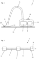
- Figure 1 shows a schematic representation of an embodiment of a vacuum cleaner 1 according to the invention.
- Figure 2 shows a schematic representation of a suction path 2 in a vacuum cleaner 1 according to the invention.
- the vacuum cleaner 1 comprises a first suction section 5 with a floor nozzle 3, a dust container 7, a second suction section 9, and a blower motor 11 that is configured to generate a negative pressure, wherein the floor nozzle 3, the first suction section 5, the dust container 7, the second suction section 9, and the blower motor 11 form a suction path 2 in this order and are fluidly coupled to one another in such a way that air can be sucked in by the blower motor 11 through the floor nozzle 3 into the first suction section 5, the dust container 7, and the second suction section 9 and is sucked in during operation of the vacuum cleaner 1, wherein the vacuum cleaner 1 is a bagless vacuum cleaner or a vacuum cleaner 1 configured to accommodate a disposable or reusable bag, wherein the vacuum cleaner 1 is configured to carry out the method according to the invention for determining a fill level of a dust container 7 of the vacuum cleaner 1.
- the first suction section 5 describes within the scope of the invention the transition from the floor nozzle 3 to the dust container 7.
- the first suction section is shown as a suction hose.
- the second suction section 9 describes the transition from the dust container 7 to the blower motor 11 within the scope of the invention.
- Fig. 2 The second suction section is shown as an example as a connecting piece.
- the vacuum cleaner 1 additionally comprises a control unit (not shown).
- the control unit can, for example, comprise a microcontroller or microprocessor and a data memory.
- the control unit can be configured and designed to carry out all steps of the method according to the invention.
- the floor nozzle 3 has an opening 13, which forms the entrance to the suction path 2 from the floor nozzle 3 - first suction section 5, which is Figure 1 shown as a hose by way of example - dust container 7 - second suction section 9 - and blower motor 11. Air thus enters the suction path 2 through the opening 13 of the floor nozzle 3 during operation or use of the vacuum cleaner 1, ie when the blower motor 11 is vacuuming.
- the air flow, ie the volume flow V of the air is in Fig. 2 shown.
- the floor nozzle 3 is in contact or engagement, for example, with the floor 15 or the floor covering of the floor 15.
- the structural design of the floor nozzle 3 determines a hydraulic resistance at the floor nozzle 3 when the floor nozzle 3 is used during use of the vacuum cleaner 1, together with the nature of the floor covering of the floor 15.
- the floor nozzle 3 has a floor covering detection device 17.
- the floor covering detection device allows automatic detection of whether the floor nozzle 3 is in contact with a hard floor or a carpet, e.g., a deep-pile carpet. Based on the detected floor covering, the process for determining the fill level of the dust container 7 can then be paused or continued, for example.
- the fill level of the dust container 7 is determined to be "maximally full" or, alternatively, filled to a predetermined level, a user is given a notification by means of the notification means 19 in the form of an LED.
- an acoustic means can also be used and/or the power of the fan motor 11 can be reduced.
- An example of an acoustic means can be a spoken notification text, a signal tone, or a sequence of signal tones.
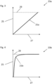
- Figures 3 and 4 each show an example of a fill level characteristic curve 21a and 21b with a first characteristic 23a and a second characteristic 23b, respectively.
- the fill level characteristic curve is shown as the fill level of the dust container 7 on the y-axis 25 as an example depending on a differential pressure, ie the difference in the negative pressure in the second section (first parameter) and at the floor nozzle (second parameter), on the x-axis 27.
- the value on the y-axis, which corresponds to the state "maximally filled" is shown as a horizontal dashed limit line 29.
- the first characteristic 23a shows, by way of example, a fill level on the y-axis 25 of the dust container 7 of the vacuum cleaner 1 that increases linearly with increasing differential pressure on the x-axis 27.
- This can be an example of a first characteristic of a fill level characteristic curve of a vacuum cleaner 1 with a disposable or reusable bag.
- the second characteristic 23b shows, by way of example, a fill level on the y-axis 25 increasing while the differential pressure on the x-axis 27 remains low. Shortly before reaching the "maximally full" state, represented by the limit line 29, the differential pressure on the x-axis 27 increases sharply.
- This can be an example of a second characteristic of a fill level curve of a bagless vacuum cleaner 1. In this case, the abrupt increase in the differential pressure can be explained by a collapse of the pressure in the dust container 7.
Landscapes
- Engineering & Computer Science (AREA)
- Mechanical Engineering (AREA)
- Electric Vacuum Cleaner (AREA)
Claims (14)
- Procédé permettant de déterminer un degré de remplissage d'un réservoir à poussière (7) d'un aspirateur (1), dans lequel l'aspirateur (1) présente :une première section d'aspiration (5) comportant une buse de sol (3),un réservoir à poussière (7),une seconde section d'aspiration (9),un moteur de soufflante (11) configuré pour générer une dépression, dans lequel la buse de sol (3), la première section d'aspiration (5), le réservoir à poussière (7), la seconde section d'aspiration (9) et le moteur de soufflante (11) forment dans cet ordre un chemin d'aspiration (2) et sont accouplés de manière fluidique les uns aux autres de telle sorte que de l'air peut être aspiré et est aspiré par le moteur de soufflante (11) à travers la buse de sol (3) dans la première section d'aspiration (5), le réservoir à poussière (7) et la seconde section d'aspiration (9), dans lequel le procédé présente les étapes suivantes :- mesure d'au moins un nombre caractéristique de moteur du moteur de soufflante (11) en fonction du temps,- détermination d'un premier paramètre à partir du nombre caractéristique de moteur, dans lequel le premier paramètre est corrélé à un débit volumétrique et/ou à une dépression dans la seconde section d'aspiration (9) ou est un débit volumétrique ou une dépression dans la seconde section d'aspiration (9),- détermination d'un second paramètre, dans lequel le second paramètre est en corrélation avec un débit volumétrique et/ou une dépression au niveau de la buse de sol (3) ou est un débit volumétrique ou une dépression au niveau de la buse de sol (3),- détermination d'un degré de remplissage du réservoir à poussière (7) à partir du premier paramètre et du second paramètre, caractérisé en ce que le second paramètre est déterminé à partir de la résistance hydraulique au niveau de la buse de sol (3), d'une surface de sol détectée et du premier paramètre.
- Procédé selon la revendication 1,
dans lequel le premier paramètre est déterminé à partir du nombre caractéristique de moteur et d'une courbe caractéristique de pression qui met en corrélation le nombre caractéristique de moteur avec la dépression et/ou le débit volumétrique dans la seconde section d'aspiration (9), dans lequel le second paramètre est déterminé à partir de la résistance hydraulique au niveau de la buse de sol (3), d'une surface de sol détectée et de la dépression et/ou du débit volumétrique dans la seconde section d'aspiration (9). - Procédé selon l'une des revendications 1 à 2,
dans lequel le degré de remplissage du réservoir à poussière (7) est déterminé à partir du débit volumique au niveau de la buse de sol (3) et du débit volumique dans la seconde section d'aspiration ou de la dépression au niveau de la buse de sol (3) et de la dépression dans la seconde section d'aspiration (9). - Procédé selon l'une des revendications 1 à 3, dans lequel le nombre caractéristique de moteur comprend une ou plusieurs des grandeurs caractéristiques suivantes : vitesse de rotation du moteur de soufflante (11), tension appliquée au moteur de soufflante (11), courant absorbé par le moteur de soufflante (11), puissance absorbée par le moteur de soufflante (11).
- Procédé selon l'une des revendications 1 à 4, dans lequel la détermination du degré de remplissage du réservoir à poussière (7) est effectuée sur la base d'une courbe caractéristique de niveau de remplissage (21a, 21b) qui met en corrélation le degré de remplissage du réservoir à poussière (7) avec le premier paramètre et le second paramètre.
- Procédé selon l'une des revendications 1 à 5, dans lequel le réservoir à poussière (7) est conçu pour recevoir un sac jetable ou réutilisable et la courbe caractéristique de niveau de remplissage (21a, 21b) décrit une première courbe (23a).
- Procédé selon l'une des revendications 1 à 5, dans lequel le réservoir à poussière (7) est sans sac et la courbe caractéristique de niveau de remplissage (21a, 21b) décrit une seconde courbe (23b).
- Procédé selon l'une des revendications 1 à 7, dans lequel, lors d'un changement du sac jetable ou réutilisable ou d'un vidage du réservoir à poussière (7) sans sac, le degré de remplissage du réservoir à poussière (7) est mis à zéro manuellement ou automatiquement.
- Procédé selon l'une des revendications 1 à 8, dans lequel le procédé permettant de déterminer le degré de remplissage du réservoir à poussière (7) est mis en pause lorsqu'un changement de contact de la buse de sol (3) d'un sol dur à un tapis est détecté et/ou le procédé permettant de déterminer le degré de remplissage du réservoir à poussière (7) est poursuivi lorsqu'un changement de contact de la buse de sol (3) d'un tapis à un sol dur est détecté.
- Procédé selon la revendication 9, dans lequel le changement de contact de la buse de sol (3) du sol dur à un tapis ou d'un tapis à un sol dur est détecté par un dispositif permettant la détection de revêtement de sol (17).
- Procédé selon la revendication 9, dans lequel le changement de contact de la buse de sol (3) d'un sol dur à un tapis est détecté par les étapes suivantes :- constatation d'un changement brutal du nombre caractéristique de moteur de soufflante (11) et/ou du premier paramètre,- comparaison du changement brutal avec la courbe caractéristique connue au préalable et/ou le degré de remplissage du réservoir à poussière (7),- constatation d'un passage du sol dur à un tapis lorsque le changement brutal constaté n'est pas en corrélation avec un degré de remplissage maximal du réservoir à poussière (7).
- Procédé selon l'une des revendications 1 à 11,dans lequel une indication est fournie à un utilisateur lorsqu'un degré de remplissage maximal du réservoir à poussière (7) est constaté,dans lequel la fourniture de l'indication comprend un ou plusieurs des moyens d'indication (19) suivants : actionnement d'un moyen optique, actionnement d'un moyen acoustique et/ou réduction de la puissance du moteur de soufflante (11).
- Procédé selon la revendication 12, dans lequel les indications sont fournies successivement dans le temps par différents moyens d'indication (19).
- Aspirateur (1) comportantune première section d'aspiration (5) comportant une buse de sol (3),un réservoir à poussière (7),une seconde section d'aspiration (9),un moteur de soufflante (11) configuré pour générer une dépression, dans lequel la buse de sol (3), la première section d'aspiration (5), le réservoir à poussière (7), la seconde section d'aspiration (9) et le moteur de soufflante (11) forment dans cet ordre un chemin d'aspiration (2) et sont accouplés de manière fluidique les uns aux autres de telle sorte que de l'air peut être aspiré par le moteur de soufflante (11) à travers la buse de sol (3) dans la première section d'aspiration (5), le réservoir à poussière (7) et la seconde section d'aspiration (9),dans lequel l'aspirateur (1) est un aspirateur (1) sans sac ou un aspirateur (1) conçu pour recevoir un sac jetable ou réutilisable,dans lequel l'aspirateur (1) est configuré pour mettre en œuvre le procédé selon les revendications 1 à 13.
Applications Claiming Priority (1)
| Application Number | Priority Date | Filing Date | Title |
|---|---|---|---|
| DE102022129395.5A DE102022129395A1 (de) | 2022-11-08 | 2022-11-08 | Verfahren zur Bestimmung eines Füllgrades eines Staubbehälters und Staubsauger |
Publications (3)
| Publication Number | Publication Date |
|---|---|
| EP4368087A1 EP4368087A1 (fr) | 2024-05-15 |
| EP4368087C0 EP4368087C0 (fr) | 2025-03-19 |
| EP4368087B1 true EP4368087B1 (fr) | 2025-03-19 |
Family
ID=88297041
Family Applications (1)
| Application Number | Title | Priority Date | Filing Date |
|---|---|---|---|
| EP23202331.7A Active EP4368087B1 (fr) | 2022-11-08 | 2023-10-09 | Procédé de détermination d'un degré de remplissage d'un récipient à poussière et aspirateur |
Country Status (2)
| Country | Link |
|---|---|
| EP (1) | EP4368087B1 (fr) |
| DE (1) | DE102022129395A1 (fr) |
Families Citing this family (1)
| Publication number | Priority date | Publication date | Assignee | Title |
|---|---|---|---|---|
| CN121263117A (zh) | 2024-03-04 | 2026-01-02 | 尚科宁家运营有限公司 | 手持表面清洁器 |
Family Cites Families (3)
| Publication number | Priority date | Publication date | Assignee | Title |
|---|---|---|---|---|
| DE102008019908A1 (de) * | 2008-04-21 | 2009-10-22 | Vorwerk & Co. Interholding Gmbh | Verfahren zur Erzeugung eines Filterwechsel-Anzeigesignals |
| DE102011052023A1 (de) * | 2011-07-21 | 2013-01-24 | Miele & Cie. Kg | Verfahren zur Füllstandsüberwachung bei einem Staubsauger |
| DE102015214036A1 (de) * | 2015-07-24 | 2017-01-26 | BSH Hausgeräte GmbH | Vorrichtung zur Steuerung einer Reinigung einer Filtereinheit für Staubsauger |
-
2022
- 2022-11-08 DE DE102022129395.5A patent/DE102022129395A1/de not_active Withdrawn
-
2023
- 2023-10-09 EP EP23202331.7A patent/EP4368087B1/fr active Active
Also Published As
| Publication number | Publication date |
|---|---|
| EP4368087A1 (fr) | 2024-05-15 |
| EP4368087C0 (fr) | 2025-03-19 |
| DE102022129395A1 (de) | 2024-05-08 |
Similar Documents
| Publication | Publication Date | Title |
|---|---|---|
| EP2222215B1 (fr) | Dispositif de commande ou de régulation de la puissance moteur d'un aspirateur | |
| DE102007057589A1 (de) | Luft-Volumenstrom- und Schiebekraft-Regelungsvorrichtung | |
| EP2875767B1 (fr) | Procédé destiné au fonctionnement d'un aspirateur et aspirateur | |
| DE102007061146A1 (de) | Verfahren zur Auswertung eines Partikelsignals und Saugdüse für einen Staubsauger | |
| EP4368087B1 (fr) | Procédé de détermination d'un degré de remplissage d'un récipient à poussière et aspirateur | |
| EP2595522B1 (fr) | Procédé et dispositif de commande de performance d'un moteur de soufflerie pour un aspirateur | |
| DE102008010068A1 (de) | Vorrichtung zur automatischen Saugleistungsregelung eines Staubsaugers | |
| EP2548490A2 (fr) | Procédé de surveillance du niveau de remplissage d'un aspirateur et aspirateur pour réaliser un tel procédé | |
| DE202008002310U1 (de) | Vorrichtung zur automatischen Saugleistungsregelung eines Staubsaugers | |
| DE102015100353A1 (de) | Verfahren zur Steuerung eines Staubsaugers, Steuereinrichtung für einen Staubsauger und Staubsauger | |
| DE102017112741A1 (de) | Staubsauger mit Objekterkennung und Verfahren zum Betreiben eines Staubsaugers | |
| EP2505115B1 (fr) | Aspirateur et procédé destiné au fonctionnement en fonction de la durée de fonctionnement d'un aspirateur | |
| DE19830737C2 (de) | Verfahren und Vorrichtung zur Steuerung eines Sauggerätes mit einer Turbine | |
| DE102011050260B4 (de) | Staubsauger und Verfahren zur Auswertung eines Partikelsignals in einem Staubsauger | |
| WO2012013483A2 (fr) | Dispositif et procédé pour faire fonctionner un aspirateur | |
| EP3437535B1 (fr) | Aspirateur | |
| EP4212082B1 (fr) | Aspirateur, de préférence aspirateur à main | |
| DE102008019908A1 (de) | Verfahren zur Erzeugung eines Filterwechsel-Anzeigesignals | |
| DE4304264A1 (de) | Eigendiagnose für einen Staubsauger und Verfahren zu deren Betrieb | |
| EP3821778B1 (fr) | Aspirateur et procédé de fonctionnement d'un aspirateur | |
| EP2457487B1 (fr) | Dispositif de détermination du degré de remplissage d'un récipient de collecte de poussière pour un aspirateur | |
| DE102018216306B3 (de) | Verfahren zur Überwachung einer austauschbaren Einheit, sowie Hausgerät mit einer austauschbaren Einheit | |
| DE102011079118B4 (de) | Staubsauger | |
| DE102018128838A1 (de) | Verfahren zum Betrieb eines Staubsaugersystems sowie Staubsaugersystem | |
| DE102018107027B4 (de) | Saugreinigungsgerät mit einer Detektionseinrichtung zur Detektion von elektrisch geladenen Partikeln |
Legal Events
| Date | Code | Title | Description |
|---|---|---|---|
| PUAI | Public reference made under article 153(3) epc to a published international application that has entered the european phase |
Free format text: ORIGINAL CODE: 0009012 |
|
| STAA | Information on the status of an ep patent application or granted ep patent |
Free format text: STATUS: THE APPLICATION HAS BEEN PUBLISHED |
|
| AK | Designated contracting states |
Kind code of ref document: A1 Designated state(s): AL AT BE BG CH CY CZ DE DK EE ES FI FR GB GR HR HU IE IS IT LI LT LU LV MC ME MK MT NL NO PL PT RO RS SE SI SK SM TR |
|
| STAA | Information on the status of an ep patent application or granted ep patent |
Free format text: STATUS: REQUEST FOR EXAMINATION WAS MADE |
|
| 17P | Request for examination filed |
Effective date: 20241115 |
|
| RBV | Designated contracting states (corrected) |
Designated state(s): AL AT BE BG CH CY CZ DE DK EE ES FI FR GB GR HR HU IE IS IT LI LT LU LV MC ME MK MT NL NO PL PT RO RS SE SI SK SM TR |
|
| GRAP | Despatch of communication of intention to grant a patent |
Free format text: ORIGINAL CODE: EPIDOSNIGR1 |
|
| STAA | Information on the status of an ep patent application or granted ep patent |
Free format text: STATUS: GRANT OF PATENT IS INTENDED |
|
| INTG | Intention to grant announced |
Effective date: 20250102 |
|
| GRAS | Grant fee paid |
Free format text: ORIGINAL CODE: EPIDOSNIGR3 |
|
| GRAA | (expected) grant |
Free format text: ORIGINAL CODE: 0009210 |
|
| STAA | Information on the status of an ep patent application or granted ep patent |
Free format text: STATUS: THE PATENT HAS BEEN GRANTED |
|
| AK | Designated contracting states |
Kind code of ref document: B1 Designated state(s): AL AT BE BG CH CY CZ DE DK EE ES FI FR GB GR HR HU IE IS IT LI LT LU LV MC ME MK MT NL NO PL PT RO RS SE SI SK SM TR |
|
| REG | Reference to a national code |
Ref country code: GB Ref legal event code: FG4D Free format text: NOT ENGLISH |
|
| REG | Reference to a national code |
Ref country code: CH Ref legal event code: EP |
|
| REG | Reference to a national code |
Ref country code: DE Ref legal event code: R096 Ref document number: 502023000699 Country of ref document: DE |
|
| REG | Reference to a national code |
Ref country code: IE Ref legal event code: FG4D Free format text: LANGUAGE OF EP DOCUMENT: GERMAN |
|
| U01 | Request for unitary effect filed |
Effective date: 20250319 |
|
| U07 | Unitary effect registered |
Designated state(s): AT BE BG DE DK EE FI FR IT LT LU LV MT NL PT RO SE SI Effective date: 20250325 |
|
| REG | Reference to a national code |
Ref country code: GB Ref legal event code: 746 Effective date: 20250414 |
|
| PG25 | Lapsed in a contracting state [announced via postgrant information from national office to epo] |
Ref country code: RS Free format text: LAPSE BECAUSE OF FAILURE TO SUBMIT A TRANSLATION OF THE DESCRIPTION OR TO PAY THE FEE WITHIN THE PRESCRIBED TIME-LIMIT Effective date: 20250619 |
|
| PG25 | Lapsed in a contracting state [announced via postgrant information from national office to epo] |
Ref country code: NO Free format text: LAPSE BECAUSE OF FAILURE TO SUBMIT A TRANSLATION OF THE DESCRIPTION OR TO PAY THE FEE WITHIN THE PRESCRIBED TIME-LIMIT Effective date: 20250619 |
|
| PG25 | Lapsed in a contracting state [announced via postgrant information from national office to epo] |
Ref country code: HR Free format text: LAPSE BECAUSE OF FAILURE TO SUBMIT A TRANSLATION OF THE DESCRIPTION OR TO PAY THE FEE WITHIN THE PRESCRIBED TIME-LIMIT Effective date: 20250319 |
|
| PG25 | Lapsed in a contracting state [announced via postgrant information from national office to epo] |
Ref country code: GR Free format text: LAPSE BECAUSE OF FAILURE TO SUBMIT A TRANSLATION OF THE DESCRIPTION OR TO PAY THE FEE WITHIN THE PRESCRIBED TIME-LIMIT Effective date: 20250620 |
|
| PG25 | Lapsed in a contracting state [announced via postgrant information from national office to epo] |
Ref country code: SM Free format text: LAPSE BECAUSE OF FAILURE TO SUBMIT A TRANSLATION OF THE DESCRIPTION OR TO PAY THE FEE WITHIN THE PRESCRIBED TIME-LIMIT Effective date: 20250319 |
|
| PG25 | Lapsed in a contracting state [announced via postgrant information from national office to epo] |
Ref country code: ES Free format text: LAPSE BECAUSE OF FAILURE TO SUBMIT A TRANSLATION OF THE DESCRIPTION OR TO PAY THE FEE WITHIN THE PRESCRIBED TIME-LIMIT Effective date: 20250319 |
|
| PG25 | Lapsed in a contracting state [announced via postgrant information from national office to epo] |
Ref country code: PL Free format text: LAPSE BECAUSE OF FAILURE TO SUBMIT A TRANSLATION OF THE DESCRIPTION OR TO PAY THE FEE WITHIN THE PRESCRIBED TIME-LIMIT Effective date: 20250319 |
|
| PGFP | Annual fee paid to national office [announced via postgrant information from national office to epo] |
Ref country code: TR Payment date: 20250926 Year of fee payment: 3 |
|
| PG25 | Lapsed in a contracting state [announced via postgrant information from national office to epo] |
Ref country code: CZ Free format text: LAPSE BECAUSE OF FAILURE TO SUBMIT A TRANSLATION OF THE DESCRIPTION OR TO PAY THE FEE WITHIN THE PRESCRIBED TIME-LIMIT Effective date: 20250319 |
|
| PG25 | Lapsed in a contracting state [announced via postgrant information from national office to epo] |
Ref country code: SK Free format text: LAPSE BECAUSE OF FAILURE TO SUBMIT A TRANSLATION OF THE DESCRIPTION OR TO PAY THE FEE WITHIN THE PRESCRIBED TIME-LIMIT Effective date: 20250319 |
|
| PG25 | Lapsed in a contracting state [announced via postgrant information from national office to epo] |
Ref country code: IS Free format text: LAPSE BECAUSE OF FAILURE TO SUBMIT A TRANSLATION OF THE DESCRIPTION OR TO PAY THE FEE WITHIN THE PRESCRIBED TIME-LIMIT Effective date: 20250719 |
|
| U20 | Renewal fee for the european patent with unitary effect paid |
Year of fee payment: 3 Effective date: 20251031 |
|
| PLBE | No opposition filed within time limit |
Free format text: ORIGINAL CODE: 0009261 |
|
| STAA | Information on the status of an ep patent application or granted ep patent |
Free format text: STATUS: NO OPPOSITION FILED WITHIN TIME LIMIT |
|
| REG | Reference to a national code |
Ref country code: CH Ref legal event code: L10 Free format text: ST27 STATUS EVENT CODE: U-0-0-L10-L00 (AS PROVIDED BY THE NATIONAL OFFICE) Effective date: 20260128 |
|
| 26N | No opposition filed |
Effective date: 20251222 |