EP4368227B1 - Distributeur de liquide pour application nasale et dispositif de pompage - Google Patents
Distributeur de liquide pour application nasale et dispositif de pompage Download PDFInfo
- Publication number
- EP4368227B1 EP4368227B1 EP22206494.1A EP22206494A EP4368227B1 EP 4368227 B1 EP4368227 B1 EP 4368227B1 EP 22206494 A EP22206494 A EP 22206494A EP 4368227 B1 EP4368227 B1 EP 4368227B1
- Authority
- EP
- European Patent Office
- Prior art keywords
- component
- pump
- channel
- nasal
- liquid
- Prior art date
- Legal status (The legal status is an assumption and is not a legal conclusion. Google has not performed a legal analysis and makes no representation as to the accuracy of the status listed.)
- Active
Links
Images


Classifications
-
- A—HUMAN NECESSITIES
- A61—MEDICAL OR VETERINARY SCIENCE; HYGIENE
- A61M—DEVICES FOR INTRODUCING MEDIA INTO, OR ONTO, THE BODY; DEVICES FOR TRANSDUCING BODY MEDIA OR FOR TAKING MEDIA FROM THE BODY; DEVICES FOR PRODUCING OR ENDING SLEEP OR STUPOR
- A61M11/00—Sprayers or atomisers specially adapted for therapeutic purposes
-
- A—HUMAN NECESSITIES
- A61—MEDICAL OR VETERINARY SCIENCE; HYGIENE
- A61M—DEVICES FOR INTRODUCING MEDIA INTO, OR ONTO, THE BODY; DEVICES FOR TRANSDUCING BODY MEDIA OR FOR TAKING MEDIA FROM THE BODY; DEVICES FOR PRODUCING OR ENDING SLEEP OR STUPOR
- A61M11/00—Sprayers or atomisers specially adapted for therapeutic purposes
- A61M11/006—Sprayers or atomisers specially adapted for therapeutic purposes operated by applying mechanical pressure to the liquid to be sprayed or atomised
- A61M11/007—Syringe-type or piston-type sprayers or atomisers
-
- A—HUMAN NECESSITIES
- A61—MEDICAL OR VETERINARY SCIENCE; HYGIENE
- A61M—DEVICES FOR INTRODUCING MEDIA INTO, OR ONTO, THE BODY; DEVICES FOR TRANSDUCING BODY MEDIA OR FOR TAKING MEDIA FROM THE BODY; DEVICES FOR PRODUCING OR ENDING SLEEP OR STUPOR
- A61M15/00—Inhalators
- A61M15/0001—Details of inhalators; Constructional features thereof
- A61M15/0013—Details of inhalators; Constructional features thereof with inhalation check valves
- A61M15/0015—Details of inhalators; Constructional features thereof with inhalation check valves located upstream of the dispenser, i.e. not traversed by the product
-
- A—HUMAN NECESSITIES
- A61—MEDICAL OR VETERINARY SCIENCE; HYGIENE
- A61M—DEVICES FOR INTRODUCING MEDIA INTO, OR ONTO, THE BODY; DEVICES FOR TRANSDUCING BODY MEDIA OR FOR TAKING MEDIA FROM THE BODY; DEVICES FOR PRODUCING OR ENDING SLEEP OR STUPOR
- A61M15/00—Inhalators
- A61M15/0001—Details of inhalators; Constructional features thereof
- A61M15/0021—Mouthpieces therefor
-
- A—HUMAN NECESSITIES
- A61—MEDICAL OR VETERINARY SCIENCE; HYGIENE
- A61M—DEVICES FOR INTRODUCING MEDIA INTO, OR ONTO, THE BODY; DEVICES FOR TRANSDUCING BODY MEDIA OR FOR TAKING MEDIA FROM THE BODY; DEVICES FOR PRODUCING OR ENDING SLEEP OR STUPOR
- A61M15/00—Inhalators
- A61M15/08—Inhaling devices inserted into the nose
-
- A—HUMAN NECESSITIES
- A61—MEDICAL OR VETERINARY SCIENCE; HYGIENE
- A61M—DEVICES FOR INTRODUCING MEDIA INTO, OR ONTO, THE BODY; DEVICES FOR TRANSDUCING BODY MEDIA OR FOR TAKING MEDIA FROM THE BODY; DEVICES FOR PRODUCING OR ENDING SLEEP OR STUPOR
- A61M31/00—Devices for introducing or retaining media, e.g. remedies, in cavities of the body
-
- B—PERFORMING OPERATIONS; TRANSPORTING
- B05—SPRAYING OR ATOMISING IN GENERAL; APPLYING FLUENT MATERIALS TO SURFACES, IN GENERAL
- B05B—SPRAYING APPARATUS; ATOMISING APPARATUS; NOZZLES
- B05B1/00—Nozzles, spray heads or other outlets, with or without auxiliary devices such as valves, heating means
- B05B1/34—Nozzles, spray heads or other outlets, with or without auxiliary devices such as valves, heating means designed to influence the nature of flow of the liquid or other fluent material, e.g. to produce swirl
- B05B1/3405—Nozzles, spray heads or other outlets, with or without auxiliary devices such as valves, heating means designed to influence the nature of flow of the liquid or other fluent material, e.g. to produce swirl to produce swirl
- B05B1/341—Nozzles, spray heads or other outlets, with or without auxiliary devices such as valves, heating means designed to influence the nature of flow of the liquid or other fluent material, e.g. to produce swirl to produce swirl before discharging the liquid or other fluent material, e.g. in a swirl chamber upstream the spray outlet
- B05B1/3421—Nozzles, spray heads or other outlets, with or without auxiliary devices such as valves, heating means designed to influence the nature of flow of the liquid or other fluent material, e.g. to produce swirl to produce swirl before discharging the liquid or other fluent material, e.g. in a swirl chamber upstream the spray outlet with channels emerging substantially tangentially in the swirl chamber
- B05B1/3431—Nozzles, spray heads or other outlets, with or without auxiliary devices such as valves, heating means designed to influence the nature of flow of the liquid or other fluent material, e.g. to produce swirl to produce swirl before discharging the liquid or other fluent material, e.g. in a swirl chamber upstream the spray outlet with channels emerging substantially tangentially in the swirl chamber the channels being formed at the interface of cooperating elements, e.g. by means of grooves
- B05B1/3436—Nozzles, spray heads or other outlets, with or without auxiliary devices such as valves, heating means designed to influence the nature of flow of the liquid or other fluent material, e.g. to produce swirl to produce swirl before discharging the liquid or other fluent material, e.g. in a swirl chamber upstream the spray outlet with channels emerging substantially tangentially in the swirl chamber the channels being formed at the interface of cooperating elements, e.g. by means of grooves the interface being a plane perpendicular to the outlet axis
-
- B—PERFORMING OPERATIONS; TRANSPORTING
- B05—SPRAYING OR ATOMISING IN GENERAL; APPLYING FLUENT MATERIALS TO SURFACES, IN GENERAL
- B05B—SPRAYING APPARATUS; ATOMISING APPARATUS; NOZZLES
- B05B1/00—Nozzles, spray heads or other outlets, with or without auxiliary devices such as valves, heating means
- B05B1/34—Nozzles, spray heads or other outlets, with or without auxiliary devices such as valves, heating means designed to influence the nature of flow of the liquid or other fluent material, e.g. to produce swirl
- B05B1/3405—Nozzles, spray heads or other outlets, with or without auxiliary devices such as valves, heating means designed to influence the nature of flow of the liquid or other fluent material, e.g. to produce swirl to produce swirl
- B05B1/341—Nozzles, spray heads or other outlets, with or without auxiliary devices such as valves, heating means designed to influence the nature of flow of the liquid or other fluent material, e.g. to produce swirl to produce swirl before discharging the liquid or other fluent material, e.g. in a swirl chamber upstream the spray outlet
- B05B1/3421—Nozzles, spray heads or other outlets, with or without auxiliary devices such as valves, heating means designed to influence the nature of flow of the liquid or other fluent material, e.g. to produce swirl to produce swirl before discharging the liquid or other fluent material, e.g. in a swirl chamber upstream the spray outlet with channels emerging substantially tangentially in the swirl chamber
- B05B1/3431—Nozzles, spray heads or other outlets, with or without auxiliary devices such as valves, heating means designed to influence the nature of flow of the liquid or other fluent material, e.g. to produce swirl to produce swirl before discharging the liquid or other fluent material, e.g. in a swirl chamber upstream the spray outlet with channels emerging substantially tangentially in the swirl chamber the channels being formed at the interface of cooperating elements, e.g. by means of grooves
- B05B1/3447—Nozzles, spray heads or other outlets, with or without auxiliary devices such as valves, heating means designed to influence the nature of flow of the liquid or other fluent material, e.g. to produce swirl to produce swirl before discharging the liquid or other fluent material, e.g. in a swirl chamber upstream the spray outlet with channels emerging substantially tangentially in the swirl chamber the channels being formed at the interface of cooperating elements, e.g. by means of grooves the interface being a cylinder having the same axis as the outlet
-
- B—PERFORMING OPERATIONS; TRANSPORTING
- B05—SPRAYING OR ATOMISING IN GENERAL; APPLYING FLUENT MATERIALS TO SURFACES, IN GENERAL
- B05B—SPRAYING APPARATUS; ATOMISING APPARATUS; NOZZLES
- B05B11/00—Single-unit hand-held apparatus in which flow of contents is produced by the muscular force of the operator at the moment of use
- B05B11/0005—Components or details
- B05B11/0062—Outlet valves actuated by the pressure of the fluid to be sprayed
- B05B11/0064—Lift valves
- B05B11/0067—Lift valves having a valve seat located downstream the valve element
-
- B—PERFORMING OPERATIONS; TRANSPORTING
- B05—SPRAYING OR ATOMISING IN GENERAL; APPLYING FLUENT MATERIALS TO SURFACES, IN GENERAL
- B05B—SPRAYING APPARATUS; ATOMISING APPARATUS; NOZZLES
- B05B11/00—Single-unit hand-held apparatus in which flow of contents is produced by the muscular force of the operator at the moment of use
- B05B11/01—Single-unit hand-held apparatus in which flow of contents is produced by the muscular force of the operator at the moment of use characterised by the means producing the flow
- B05B11/10—Pump arrangements for transferring the contents from the container to a pump chamber by a sucking effect and forcing the contents out through the dispensing nozzle
- B05B11/1042—Components or details
- B05B11/1043—Sealing or attachment arrangements between pump and container
- B05B11/1046—Sealing or attachment arrangements between pump and container the pump chamber being arranged substantially coaxially to the neck of the container
- B05B11/1047—Sealing or attachment arrangements between pump and container the pump chamber being arranged substantially coaxially to the neck of the container the pump being preassembled as an independent unit before being mounted on the container
-
- F—MECHANICAL ENGINEERING; LIGHTING; HEATING; WEAPONS; BLASTING
- F04—POSITIVE - DISPLACEMENT MACHINES FOR LIQUIDS; PUMPS FOR LIQUIDS OR ELASTIC FLUIDS
- F04B—POSITIVE-DISPLACEMENT MACHINES FOR LIQUIDS; PUMPS
- F04B53/00—Component parts, details or accessories not provided for in, or of interest apart from, groups F04B1/00 - F04B23/00 or F04B39/00 - F04B47/00
-
- F—MECHANICAL ENGINEERING; LIGHTING; HEATING; WEAPONS; BLASTING
- F04—POSITIVE - DISPLACEMENT MACHINES FOR LIQUIDS; PUMPS FOR LIQUIDS OR ELASTIC FLUIDS
- F04B—POSITIVE-DISPLACEMENT MACHINES FOR LIQUIDS; PUMPS
- F04B53/00—Component parts, details or accessories not provided for in, or of interest apart from, groups F04B1/00 - F04B23/00 or F04B39/00 - F04B47/00
- F04B53/10—Valves; Arrangement of valves
-
- A—HUMAN NECESSITIES
- A61—MEDICAL OR VETERINARY SCIENCE; HYGIENE
- A61M—DEVICES FOR INTRODUCING MEDIA INTO, OR ONTO, THE BODY; DEVICES FOR TRANSDUCING BODY MEDIA OR FOR TAKING MEDIA FROM THE BODY; DEVICES FOR PRODUCING OR ENDING SLEEP OR STUPOR
- A61M15/00—Inhalators
- A61M15/0065—Inhalators with dosage or measuring devices
-
- A—HUMAN NECESSITIES
- A61—MEDICAL OR VETERINARY SCIENCE; HYGIENE
- A61M—DEVICES FOR INTRODUCING MEDIA INTO, OR ONTO, THE BODY; DEVICES FOR TRANSDUCING BODY MEDIA OR FOR TAKING MEDIA FROM THE BODY; DEVICES FOR PRODUCING OR ENDING SLEEP OR STUPOR
- A61M2202/00—Special media to be introduced, removed or treated
- A61M2202/04—Liquids
- A61M2202/0468—Liquids non-physiological
-
- A—HUMAN NECESSITIES
- A61—MEDICAL OR VETERINARY SCIENCE; HYGIENE
- A61M—DEVICES FOR INTRODUCING MEDIA INTO, OR ONTO, THE BODY; DEVICES FOR TRANSDUCING BODY MEDIA OR FOR TAKING MEDIA FROM THE BODY; DEVICES FOR PRODUCING OR ENDING SLEEP OR STUPOR
- A61M2206/00—Characteristics of a physical parameter; associated device therefor
- A61M2206/10—Flow characteristics
- A61M2206/16—Rotating swirling helical flow, e.g. by tangential inflows
-
- A—HUMAN NECESSITIES
- A61—MEDICAL OR VETERINARY SCIENCE; HYGIENE
- A61M—DEVICES FOR INTRODUCING MEDIA INTO, OR ONTO, THE BODY; DEVICES FOR TRANSDUCING BODY MEDIA OR FOR TAKING MEDIA FROM THE BODY; DEVICES FOR PRODUCING OR ENDING SLEEP OR STUPOR
- A61M2210/00—Anatomical parts of the body
- A61M2210/06—Head
- A61M2210/0618—Nose
-
- B—PERFORMING OPERATIONS; TRANSPORTING
- B05—SPRAYING OR ATOMISING IN GENERAL; APPLYING FLUENT MATERIALS TO SURFACES, IN GENERAL
- B05B—SPRAYING APPARATUS; ATOMISING APPARATUS; NOZZLES
- B05B11/00—Single-unit hand-held apparatus in which flow of contents is produced by the muscular force of the operator at the moment of use
- B05B11/01—Single-unit hand-held apparatus in which flow of contents is produced by the muscular force of the operator at the moment of use characterised by the means producing the flow
- B05B11/10—Pump arrangements for transferring the contents from the container to a pump chamber by a sucking effect and forcing the contents out through the dispensing nozzle
- B05B11/1001—Piston pumps
- B05B11/1023—Piston pumps having an outlet valve opened by deformation or displacement of the piston relative to its actuating stem
Definitions
- the invention relates to a nasal dispenser for the nasal application of atomized liquids and to a pumping device particularly suitable for such a nasal dispenser.
- Nasal dispensers of this type are used to administer liquid in atomized form nasally through the nostrils of a patient, particularly pharmaceutical liquids to relieve breathing difficulties associated with cold symptoms.
- the application of the atomized liquid in the form of a conical spray jet promotes the desired distribution of the liquid in the respiratory tract.
- a spray jet of atomized liquid can be produced in various ways with nasal dispensers, for example by using a nozzle plate with a large number of nozzle openings or by using a swirl chamber in which the liquid is made to swirl quickly before being dispensed, with a discharge opening provided on the front of the swirl chamber and the swirling liquid being broken up into fine droplets when discharged there.
- the use of nasal dispensers that dispense liquid in atomized form is particularly common among adults. However, children often find nasal drops easier to handle, partly because children sometimes find the spray of atomized liquid unpleasant.
- EP3412325 A1 relates to a discharge head for the nasal application of pharmaceutical liquid from a pressure accumulator, which has an outlet valve with a valve nozzle that can be acted upon against a spring force to open the outlet valve.
- the object of the invention is to provide a nasal dispenser for the nasal application of liquid in atomized form, the dispensing of which is perceived by children as less unpleasant.
- a nasal dispenser for the nasal application of liquids is proposed, in particular for use in children, which, in the usual way, has a liquid reservoir for collecting liquid before dispensing and a slim nasal applicator for insertion into the nose and for dispensing the liquid in a discharge direction.
- the nasal applicator is preferably part of a device which is linearly arranged in relation to the liquid reservoir.
- a discharge unit which can be displaced in an actuating direction and in particular parallel to the discharge direction, by pressing down which against the force of a return spring a pump device is actuated or a valve device is opened.
- the nasal applicator has an outer component and an inner component.
- the outer component forms an outer surface that is visible to the user.
- the outer component has a slim applicator tip with a distal end wall that is penetrated by a discharge opening that is designed to emit a spray jet in the discharge direction.
- the discharge direction preferably corresponds to the main extension direction of the slim applicator tip.
- the slim applicator tip is preferably rotationally symmetrical, and this refers to the basic shape.
- a design in which a thread or other secondary holding structures are provided on the outside for attaching a cap, but which otherwise have a rotationally symmetrical shape, are also to be understood as rotationally symmetrical within the meaning of the invention.
- the slim shape is expressed in the fact that its length from a root area to the distal end is preferably twice, in particular at least 2.5 times, the outside diameter in the root area.
- the root area is formed by the point that is no longer inserted when inserted into the nostril.
- the length of the applicator tip from the root area to the distal end is preferably at least 15 mm. It is therefore particularly preferred that the applicator tip has a diameter of a maximum of 7.5 mm, preferably a maximum of 6 mm, at a distance of 15 mm from the distal end.
- the inner component is inserted into the outer component. Together with the outer component, it delimits a liquid path that leads to the discharge opening, in particular a vortex chamber provided in this liquid path upstream of the discharge opening.
- the vortex chamber is formed at least partially and in particular predominantly by a recess in the inner component.
- the inner component can additionally form a discharge channel that connects the vortex chamber to a pump device. In other designs, the discharge channel is arranged between the inner component and the outer component.
- At least one swirl-generating inlet channel opens into the vortex chamber, with preferably at least two such inlet channels being provided, which are opposite one another, or more than two inlet channels which are distributed circumferentially into the preferably rotationally symmetrical vortex chamber.
- the inlet channels are angled relative to a radial direction in order to allow the liquid to flow into the vortex chamber in such a way that it enters into a rotating vortex movement.
- the inlet channel or channels are preferably formed by depressions in the inner component or by openings on an inward-facing web of the outer component.
- these depressions have a smaller depth than the adjoining vortex chamber, which is also formed by a depression, in order to cause a flow separation when the liquid flows into the vortex chamber through the step that exists due to the different depth.
- the nasal dispenser is preferably designed in such a way that a liquid flow of less than 0.7 ml/second is achieved during normal operation, preferably less than 0.6 ml/second.
- a liquid flow of 1.0 ml/second or even 1.5 ml/second is usual for conventional nasal dispensers for adults.
- the components of the nasal dispenser must be designed in such a way that the desired atomization takes place.
- a pure reduction of the liquid flow for example by a throttle in the discharge channel upstream of the vortex chamber and the inlet channels, has proven to be not ideal, since the reduced pressure downstream of the throttle makes it difficult for the vortex chamber to produce a fine atomization.
- a first alternative concerns a nasal applicator whose inner component and outer component are arranged in a fixed position relative to one another, for example by being firmly locked together by a snap connection. Together they define the vortex chamber and together circumferentially limit the inlet channels into the vortex chamber.
- the invention proposes that the inlet channels or the at least one inlet channel be designed to be particularly narrow.
- the cross-sectional area of the inlet channel at its narrowest point, which is oriented transversely to the flow direction, or in the case of a plurality of inlet channels, the sum of the cross-sectional areas of the inlet channels at their respective narrowest points, is only 0.05 mm 2 according to the invention, preferably even less, namely 0.04 mm 2 or less.
- the at least one inlet channel preferably has a cross-section that tapers in the direction of flow, so that the narrowest point with a clear cross-section of a maximum of 0.05 mm 2 according to the invention is provided at an inlet into the vortex chamber.
- the speed of the liquid therefore increases continuously when it flows in the direction of flow towards the vortex chamber.
- the size of the discharge opening is not crucial in the described design with very fine inlet channels, since in this case the inlet speed of the liquid into the vortex chamber is primarily responsible for good atomization. It is therefore proposed to make the discharge opening comparatively large.
- the discharge opening should have a cross-sectional area at its narrowest point that is larger than the cross-sectional area of the inlet channel or the sum of the cross-sectional areas of the inlet channels.
- the discharge opening preferably has a cross-sectional area of at least 0.06 mm 2 , in particular of at least 0.08 mm 2 , at its narrowest point.
- the inlet channels are formed circumferentially jointly by the outer component and the inner component. They are formed by a remaining gap that remains between an end face of the inner component and the inside of the end wall of the outer component.
- the inlet channels are formed by opposing channel walls of both components, the outer component and the inner component. The distance between these channel walls defines the channel height.
- the channel height is preferably less than 0.15 mm, preferably less than 0.12 mm. This narrow gap can be created reliably and with little manufacturing effort by providing the aforementioned recesses of appropriate depth on the front side of the inner component.
- the inlet channels are preferably provided with a greater width than height.
- the channel width i.e. the extent of the cross-sectional area of the respective inlet channel at its narrowest point transversely to the flow direction and transversely to the channel height, is preferably twice as large as the channel height.
- the channel width is preferably at least 0.15 mm, in particular preferably 0.18 mm or more.
- the second alternative proposed here relates to a nasal applicator in which the inner component is arranged movably in the outer component.
- the inner component is arranged in the outer component so as to be linearly displaceable, wherein it is pressed away from the discharge opening against the force of a return spring, in particular by increasing the fluid pressure.
- the invention proposes to design the discharge opening in a special shape in order to develop a throttling effect and at the same time achieve sufficient atomization.
- the discharge opening is designed with a particularly small cross-section, namely with a clear cross-sectional area at its narrowest point of a maximum of 0.05 mm 2 , preferably a maximum of 0.04 mm 2 .
- the discharge opening can in particular have a rotationally symmetrical shape.
- the atomization is not primarily influenced by influencing the speed of the liquid flowing into the vortex chamber, but by a particularly small discharge opening. It has been shown that this also enables atomization and the generation of a conical spray jet with a low liquid flow. In particular, This can be achieved if the average diameter of the discharge opening to the maximum diameter of the pump chamber is in a ratio of between 1:3 and 1:5.
- the inlet channels can be provided in particular in a web that surrounds the discharge opening on the inside. Depending on the relative position of the inner component, this can partially close the inlet channels in the manner of an inner panel and thus cause the variable cross-section mentioned.
- the inner component and the outer component preferably form a discharge valve together.
- the inner component preferably has a closing piston which, in the end position, covers the at least one inlet channel in the web on the inside and thereby completely prevents liquid from flowing from the inlet channel into the swirl chamber in an end position.
- the inner component and the outer component seal axially with one another in an end position by an end face of the inner component resting on the inside of the end wall of the outer component.
- the manufacture of a small discharge opening proposed according to the invention can be made easier by the discharge opening having a cross-section that is not uniform across the thickness of the end wall, i.e. not having the small cross-section mentioned across the entire thickness of the end wall.
- the discharge opening has a particularly conical or cylindrical recess on the inside or outside of the end wall, i.e. on the inlet side or outlet side, which is part of the discharge opening or represents a tapering of the end wall. This recess makes it easier to achieve the desired precision of the discharge opening in an external component manufactured by means of plastic injection molding.
- a nasal dispenser according to the invention dispenses pressurized liquid.
- the liquid is stored in a liquid reservoir designed as a pressure reservoir and is released by a manually operated valve.
- the liquid is stored in the liquid reservoir without pressure and is pumped to the discharge opening by means of a pump device.
- a pumping device is preferably provided which is connected to the liquid reservoir at an inlet side and which is connected to the discharge opening via a discharge channel.
- an actuating handle is provided which can be moved between an unactuated end position and an actuated end position, whereby this actuating handle is preferably provided in a fixed position relative to the applicator tip and is pressed down together with the applicator tip relative to the liquid reservoir in order to convey liquid from a pump chamber of the pumping device to the discharge opening.
- the pump device is preferably a piston pump with a cylinder wall and a piston sealing thereto, by means of which a pump chamber volume can be changed.
- the pump device has an inlet valve and an outlet valve on the input side and output side.
- the outlet valve is preferably designed as a pressure-dependent outlet valve which opens when there is excess pressure in the pump chamber.
- this discharge valve can simultaneously be the outlet valve of the pump device or can be provided as an additional valve in addition to a separate outlet valve of the pump device.
- the inlet valve can also be a pressure-dependent valve that opens when there is a negative pressure in the pump chamber and thereby sucks liquid from the liquid reservoir, in particular through a riser pipe.
- a path-dependent inlet valve is preferred over a pressure-dependent inlet valve. This will be described below.
- the pump device is preferably designed to deliver a relatively small amount of liquid per actuation so that the discharge does not appear unpleasant for a child. It is preferable that the nasal dispenser is used several times in succession for application into the same nostril of the child, rather than completely discharging the desired amount of liquid with one actuation.
- the pump device can be designed to convey a liquid quantity of less than 70 ⁇ l to the discharge opening when the actuating handle is moved from the unactuated end position to the actuated end position, in particular preferably less than 50 ⁇ l or even less than 30 ⁇ l.
- this small amount of liquid is pumped during an actuation from the non-actuated end position to the actuated end position of at least 4 mm, in particular of at least 6 mm, whereby the actual conveying process only needs to take place during part of this actuation.
- the comparatively large actuation length facilitates operation and reduces the required actuation force.
- the nasal dispenser is designed for a comparatively low liquid flow, i.e. in particular to achieve a discharge with an average liquid flow of less than 0.7 ml/second.
- the pump device and a discharge channel connected to it up to the discharge opening are therefore preferably designed in such a way that when actuated with a reference force of 25 Newtons, the actuation from the unactuated end position to the actuated end position leads to an average liquid flow of less than 0.7 ml/second, preferably to a liquid flow of less than 0.5 ml/second or less than 0.3 ml/second. Only the period in which a discharge takes place is taken into account here, i.e. when the outlet valve of the pump device is open.
- the invention also relates to a pumping device for a liquid dispenser, in particular a pumping device for use in a nasal dispenser of the type described above.
- a pumping device for use in a nasal dispenser of the type described above.
- a pumping device that is suitable for dispensing a small and precisely dosed amount of liquid.
- the pump device has a pump chamber which is formed by two pump components which can move relative to one another, in particular a first pump component which is part of the discharge unit and a second pump component which is part of a base which is stationary relative to the liquid reservoir.
- a displacement of the pump components leads to a change in the volume of the pump chamber.
- the pump device has an inlet valve and an outlet valve, which connect the pump device to a liquid reservoir and a discharge opening, respectively.
- the outlet valve is preferably designed as a pressure-dependent opening outlet valve and can be identical to a discharge valve of the dispenser, which can be formed by the described inner component and the described outer component.
- the inlet valve of a pump device is designed as a path-dependent opening inlet valve.
- the inlet valve is opened and closed in at least one defined relative position of the pump components.
- the inlet valve has a valve piston on the first pump component and a metering channel on the second pump component.
- the valve piston moves to close the inlet valve and thus to effect the discharge into the dosing channel.
- the valve piston is thus in sealing contact with the inside of the dosing channel.
- the valve piston and the dosing channel are preferably dimensioned in such a way that the valve piston can move out of the dosing channel again with its sealing surface at the opposite end, thus achieving a sudden termination of the discharge towards the end of the actuation.
- Inlet valves that open depending on the path are already known in principle, but known valves of this type are designed for larger liquid flows.
- the pump device has a cylindrical pump chamber wall on the first pump component and a piston surface on the inside of the cylindrical pump chamber wall on the second pump component, wherein this is structurally solved in such a way that a sleeve is provided on the second pump component, which forms both the metering channel and the piston surface.
- the sleeve points into an inner region of the cylindrical pump chamber wall.
- the inside of the sleeve forms the metering channel.
- the piston surface is provided on the outside of the sleeve and/or at the distal end of the sleeve, which permanently rests against the cylindrical pump chamber wall during operation.
- the pump chamber allows the pump chamber to be designed with a very small cross-section, since the sleeve described has a dual function. Because it directly supports the piston surface, the cylindrical pump chamber wall can be designed with a cross-section that is only slightly larger than the metering channel. Accordingly, the delivery volume is comparatively small in relation to the actuation distance.
- the cross-sectional area of the cylindrical pump chamber wall is between 10 mm 2 and 20 mm 2 , preferably between 10 mm 2 and 17 mm 2 .
- the cross-sectional area of the dosing channel is preferably between 2 mm 2 and 5 mm 2 , in particular between 3 mm 2 and 4 mm 2 .
- the piston area of the pump chamber effective for liquid delivery is preferably between 6 mm 2 and 15 mm 2 . In the case of an effective piston area of 10 mm 2 , for example, a liquid quantity of 50 ⁇ l is discharged over a dosing distance of 5 mm.
- the invention relates to a nasal dispenser of the type described both in the unfilled state before filling and in the state ready for the end customer with filled liquid reservoir.
- the liquid reservoir When filled, the liquid reservoir is preferably filled with a total liquid quantity of less than 50 ml, preferably less than 30 ml.
- a pharmaceutical liquid When filled, a pharmaceutical liquid is filled into the liquid dispenser, whereby this also includes, in particular, saline aqueous solutions.
- the pharmaceutical liquid can also be a liquid with a decongestant effect, in particular a liquid with an imidazoline component, such as oxymetazoline.
- Fig. 1 to 5 illustrate a first embodiment of a nasal dispenser 10 according to the invention.
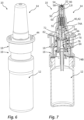
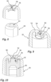
- Fig. 6 to 10 illustrate a second embodiment of a nasal dispenser 10 according to the invention.
- Both nasal dispensers 10 have a liquid reservoir 12 to which a discharge head 14 is attached.
- This discharge head 14 has a base 16 which is connected to the liquid reservoir, for example by means of a threaded or snap connection.
- the discharge head 14 also has a discharge unit 18 which is movably attached to the base 16 and can be pressed down in the direction of the base 16 in an actuation direction 6.
- the discharge unit 18 has a slim nasal applicator 40 in the form of an applicator tip 42 which tapers towards a distal end and is intended to be inserted into a nostril of a user.
- the discharge unit also has an actuation handle 44 in the form of a circumferential finger rest.
- a discharge opening 54 is provided, which is preceded by a vortex chamber 98.
- the discharge opening 54 is designed as a front-side opening in an outer component 50.
- the vortex chamber 98 is delimited by the inside of a front wall 52 of this outer component and by an inner component 60.
- the nasal dispensers each have a pump device 70 that can be activated by pressing down the discharge unit 18 against the liquid reservoir 12 and the base 16.
- the pump device conveys liquid from the liquid reservoir 12 to the discharge opening 54, the liquid flows through inlet channels 96 into the swirl chamber 98.
- the inlet channels 96 By aligning the inlet channels 96 at an angle to a radial direction, the liquid is given a swirl when it enters the swirl chamber 98.
- the liquid that has entered the swirl chamber 98 therefore rotates at high speed in a clockwise or anti-clockwise direction.
- the rotating liquid reaches the end wall 52 and the discharge opening 54 provided therein.
- the swirl of the liquid causes the liquid exiting through the discharge opening 54 to be torn into a conical spray jet of fine individual droplets at a sufficiently high speed.
- the nasal dispensers 10 shown in 6 to 10 represent two designs of nasal dispensers 10 that differ in essential details and are intended in particular for use with children.
- the nasal dispensers 10 have in common that they are specifically designed to produce a discharged liquid flow of only about 0.7 ml/second. This low liquid flow, together with fine atomization, ensures that the discharge is not perceived as very unpleasant by children. Depending on how much the liquid flow is reduced, it can even be achieved that the discharge is hardly noticed by children.
- the discharge unit 18 and the nasal applicator 40 provided on it are formed by essentially two components, namely the outer component 50 and the inner component 60.
- the liquid is conveyed to the discharge opening 54 by a pump device 70.
- the pump device 70 has an inlet valve 76 and an outlet valve 86. Beyond the outlet valve 86, the liquid flows in the direction of the discharge opening 54 through a channel 87, which is surrounded in part by the inner component 60. At the end of this channel 87, the liquid enters through radial openings into an end channel section 88, which is jointly delimited by the inner component 60 and the outer component 50. The liquid passes through this channel section 88 to two inlet channels 96.
- the inlet channels 96 are, as in particular the Fig. 3 can be seen, is limited by opposing channel walls 96A, 96B, wherein the Fig. 3 shown upper channel wall 96A is formed by the inside of the end wall 52 of the outer component 50 and wherein the in Fig. 3 shown lower channel wall 96B is formed by the end face 64 of the inner component 60.
- the end face 64 of the inner component 60 is in particular the Fig. 5
- the front surface is formed with a central depression with a depth of, for example, 0.2 mm, which together with the front wall 52 forms the vortex chamber 98.
- the inlet channels 96 are formed primarily by two further depressions which have a smaller depth of, for example, 0.1 mm, so that liquid flowing through them flows into the vortex chamber 98 via a step, thereby causing a clean flow separation.
- the inlet channels are tapered in relation to a flow direction 4. They have their narrowest cross-section immediately before the junction with the vortex chamber 98. There, the width of the inlet channels transverse to the flow direction 4 is 0.2 mm. The total cross-section of each of the two inlet channels is therefore 0.02 mm 2 , in total 0.04 mm 2 , as can be seen from the Fig. 5 shown enlarged area can be seen
- the discharge opening 54 is larger than the sum of the cross sections of the inlet channels, so that the inlet channels represent the narrowest point overall between the pump device 70 and the outlet of the liquid.
- the discharge opening is preferably rotationally symmetrical and has a diameter of at least 0.25 mm and preferably at least 0.3 mm at its narrowest point, i.e. a smallest clear cross section of at least about 0.05 mm 2 and preferably at least about 0.1 mm 2 .
- the very narrow inlet channels 96 in combination with the step at the transition between the inlet channels 96 and the swirl chamber 98, cause the liquid to flow in at high speed with little disruption.
- the narrow inlet channels 96 reduce the liquid flow achieved at normal operating speed, preferably to about 0.3 ml/second. Despite this reduced liquid flow, the high speed of the liquid as it flows into the swirl chamber 98 results in very good atomization.
- the diameter of the discharge opening 54 is therefore of little importance. In the case of the embodiment shown here, the diameter of the discharge opening 54 is about 0.3 mm. However, larger diameters would also be possible, since the advantageous atomization in this design is ensured primarily by the inlet channels 96.
- the outer component 50 and the inner component 60 are movable relative to each other and together form a discharge valve 90.
- a circumferential web 56 is provided on the inside of the front wall 52, which is interrupted by slots which, together with the inner component 60, form the inlet channels 96.
- the inner component 60 forms a closing piston 62 with its distal end, which is movable relative to the web 56. If no liquid pressure is applied, the discharge valve 90 is closed.
- the closing piston is inserted so far into the web 56 that the slots there are completely covered and thus no liquid can flow into the swirl chamber 98 delimited by the web and the closing piston. If liquid is pressurized by means of the pump device 70 of the nasal dispenser 10, the liquid pressure pushes the inner component 60 away from the discharge opening 54 against the force of a valve spring 92, so that the swirl chamber 98 is enlarged and access for the liquid is opened through the inlet channels 96.
- the design of the Fig. 6 to 10 In contrast, the discharge opening 54 is designed to be very small. It has been shown that this also makes it possible to achieve a low liquid flow and the desired atomization.
- the discharge opening 54 therefore has a cross-sectional area of 0.04 mm 2 or less at its narrowest point.
- the discharge opening is preferably rotationally symmetrical and designed with a smallest diameter of 0.2 mm and correspondingly with a cross-sectional area of less than 0.035 mm 2 .
- this end wall 52 has recesses 58 on the inside and/or outside in the area of the discharge opening.
- the maximum thickness of the end wall of approximately 0.5 mm to 0.8 mm is thus reduced in the area of the discharge opening by the recesses 58, preferably to a thickness of between 0.2 mm and 0.4 mm.
- This thickness of preferably between 0.2 mm and 0.4 mm is further preferably penetrated by a cylindrical section of the discharge opening 54, which has the aforementioned small cross-sectional area of less than 0.04 mm 2 throughout, preferably less than 0.035 mm 2 .
- the vortex chamber 98 preferably has a maximum diameter which is approximately four to eight times as large as the diameter of the discharge opening 54 and is therefore particularly preferably between 0.8 mm and 2.0 mm, in particular between 0.8 mm and 1.2 mm.
- the vortex chamber 98 preferably merges into the cylindrical section of the discharge opening 54 via a conically narrowed region, in particular formed by the aforementioned inner recess.
- the Fig. 10 When the nasal dispenser 10 is activated by pressing down the discharge unit 18, the Fig. 10
- the inlet channels 96 are made clearer due to pressure, since the closing piston 62 is spaced apart from the discharge opening.
- the liquid flows into the swirl chamber 98 and is discharged through the very narrow discharge opening 54.
- the inlet channels are significantly larger than in the design of the Fig. 1 to 5 Due to the narrow discharge opening 54, a considerable actuation resistance and the desired atomization are achieved with a simultaneous low liquid flow of less than 0.3 ml/second.
- the pump device 70 is designed in a special way.
- the pump device has an inlet valve 76 and an outlet valve 90.
- the outlet valve 90 is identical to the discharge valve 90 already mentioned.
- designs with two independent valves downstream of the pump chamber 72 of the pump device 70 are also possible.
- the inlet valve 76 differs from the design of the Fig. 1 bis5 does not have a pressure-dependent opening inlet valve, but a path-dependent opening one.
- first pump component 74A which is part of the displaceable discharge unit 18 and is firmly connected to the outer component 50, including the inner component 60.
- This first Pump component 74A has a central valve piston 77 and a circumferential web surrounding this valve piston 77, the inside of which forms a pump chamber wall 80.
- a second pump component 74B is part of the base 16.
- This second pump component 74B has a central sleeve 84 which performs the following functions:
- the sleeve 84 is penetrated by an inlet channel 85, wherein a section of the inlet channel 85 with a small cross-section forms a metering channel 78.
- This metering channel is designed such that the valve piston 77 of the first pump chamber component, when arranged in the metering channel, thereby closes the inlet channel 85 and interrupts the communicating connection between the pump chamber 72 and the liquid reservoir 12.
- the sleeve 84 also supports a piston surface 82, which is provided at the distal end of the sleeve and defines the maximum sleeve diameter.
- the piston surface 82 rests against the pump chamber wall 80.
- the discharge unit 18 If the discharge unit 18 is now pressed down, the liquid is first pressed from the pump chamber 72 through the still open inlet channel 85 back into the liquid reservoir 20 until the valve piston 77 enters the metering channel 78.
- the backflow is now interrupted and the continued depression of the discharge unit 18 causes an increase in pressure in the pump chamber 72 and correspondingly an opening of the outlet and discharge valve 90.
- This discharge takes place over an actuation distance of 5 mm, which is determined by the length of the metering channel 78.
- the valve piston 77 exits the metering channel 78 at the lower end, the communicating connection between the pump chamber 72 and the liquid reservoir 12 is restored.
- the excess pressure in the pump chamber is discharged into the liquid reservoir 12 and the discharge and outlet valve 90 closes.
- the liquid is pumped from the pump chamber 72 in the direction of the discharge opening 54.
- the sleeve 84 takes on a dual function and itself carries the piston surface 82, a pump chamber with a very small diameter can be achieved.
- the diameter of the cylindrical pump chamber wall is 4 mm and the cross-sectional area is therefore approximately 12.5 mm 2 .
- the effective piston area taking into account the valve piston 77, is even somewhat smaller and is approximately 7 mm 2 to 10 mm 2 , in the present case 8 mm 2 . Accordingly, 40 ⁇ l of liquid are conveyed and discharged over the dosing distance of 5 mm.
- the geometry of the liquid path from the pump chamber 72 to the discharge opening 54 ensures that the discharge takes place over a period of approximately 0.15 seconds with a reference actuation force of 25 Newtons, i.e. with an average liquid flow of 0.27 ml/second. This results in a soft spray jet that is almost imperceptible in the nose and is not perceived as very unpleasant by children.
Landscapes
- Health & Medical Sciences (AREA)
- Engineering & Computer Science (AREA)
- Life Sciences & Earth Sciences (AREA)
- Animal Behavior & Ethology (AREA)
- Anesthesiology (AREA)
- Biomedical Technology (AREA)
- Heart & Thoracic Surgery (AREA)
- Hematology (AREA)
- Veterinary Medicine (AREA)
- Public Health (AREA)
- General Health & Medical Sciences (AREA)
- Bioinformatics & Cheminformatics (AREA)
- Pulmonology (AREA)
- Mechanical Engineering (AREA)
- Otolaryngology (AREA)
- General Engineering & Computer Science (AREA)
- Infusion, Injection, And Reservoir Apparatuses (AREA)
Claims (15)
- Distributeur nasal (10) pour l'application nasale de liquides sous forme atomisée, notamment pour l'application nasale de liquides chez les enfants, avec les caractéristiques suivantes :a. le distributeur nasal (10) dispose d'un réservoir de liquide (12) pour recevoir du liquide avant la distribution, etb. le distributeur nasal (10) dispose d'un applicateur nasal (40) pour distribuer le liquide, etc. un composant extérieur (50) de l'applicateur nasal (40) présente une pointe d'applicateur mince (42) avec une paroi frontale distale (52) qui est traversée par une ouverture de déchargement (54) qui est configurée pour distribuer un jet de pulvérisation dans une direction de déchargement (2), etd. un composant intérieur (60) de l'applicateur nasal (40) est inséré dans le composant extérieur (50), ete. le composant extérieur (50) et le composant intérieur (60) délimitent ensemble une chambre de tourbillonnement (98) en amont de l'ouverture de déchargement (54), au moins un canal d'entrée (96) générant des tourbillons étant prévu, qui débouche dans la chambre de tourbillonnement (98),caractérisé par une des caractéristiques supplémentaires suivantes :f. le composant intérieur (60) et le composant extérieur (50) sont agencés de manière fixe l'un par rapport à l'autre et délimitent ensemble en périphérie l'au moins un canal d'entrée (96), la surface de section transversale du canal d'entrée (96) orientée transversalement à la direction d'écoulement (4) dans le canal d'entrée à son emplacement le plus étroit ou la somme des surfaces de section transversale des canaux d'entrée orientées transversalement à la direction d'écoulement (4) dans les canaux d'entrée (96) à leurs emplacements respectifs les plus étroits étant de 0,05 mm2 maximum, de préférence de 0,04 mm2 maximum, oug. le composant intérieur (60) est agencé de manière mobile dans le composant extérieur (50) et le composant intérieur (60) et le composant extérieur (50) délimitent ensemble l'au moins un canal d'entrée (96), de telle sorte que la section transversale de l'au moins un canal d'entrée (96) est variable en raison de la mobilité du composant intérieur (60) par rapport au composant extérieur (50), et l'ouverture de déchargement (54) présente à son emplacement le plus étroit une surface de section transversale de 0,05 mm2 maximum, de préférence de 0,04 mm2 maximum.
- Distributeur nasal (10) selon la revendication 1, avec les caractéristiques supplémentaires suivantes :a. le composant intérieur (60) et le composant extérieur (50) sont agencés de manière fixe l'un par rapport à l'autre, etb. l'ouverture de déchargement (54) présente, à son emplacement le plus étroit, une surface de section transversale qui est supérieure à la surface de section transversale du canal d'entrée (96) ou à la somme des surfaces de section transversale des canaux d'entrée (96).
- Distributeur nasal (10) selon la revendication 2, avec les caractéristiques supplémentaires suivantes :a. l'ouverture de déchargement (54) présente, à son emplacement le plus étroit, une surface de section transversale d'au moins 0,06 mm2,de préférence avec la caractéristique supplémentaire suivante :
b. l'ouverture de déchargement (54) présente, à son emplacement le plus étroit, une surface de section transversale d'au moins 0,08 mm2. - Distributeur nasal (10) selon l'une quelconque des revendications 1 à 3, avec les caractéristiques supplémentaires suivantes :a. le composant intérieur (60) et le composant extérieur (50) sont agencés de manière fixe l'un par rapport à l'autre, etb. l'au moins un canal d'entrée (96) est conçu à son emplacement le plus étroit de telle sorte que deux parois de canal opposées (96A, 96B) du canal d'entrée (96), dont l'une est formée par le composant intérieur (60) et l'autre par le composant extérieur (50), définissent une hauteur de canal inférieure à 0,15 mm, de préférence inférieure à 0,12 mm,de préférence avec la caractéristique supplémentaire suivante :
c. transversalement à la hauteur de canal, l'au moins un canal d'entrée (96) présente, à la section transversale la plus étroite, une largeur de canal qui est supérieure à la hauteur de canal et qui est de préférence au moins deux fois plus large que la hauteur de canal, la largeur de canal étant de préférence d'au moins 0,15 mm, notamment de préférence de 0,18 mm ou plus. - Distributeur nasal (10) selon l'une quelconque des revendications 1 à 4, avec les caractéristiques supplémentaires suivantes :a. le composant intérieur (60) et le composant extérieur (50) sont agencés de manière fixe l'un par rapport à l'autre, etb. la chambre de tourbillonnement (98) est formée par un renfoncement dans le composant intérieur (60), l'au moins un canal d'entrée (96) étant formé par un autre renfoncement dans le composant intérieur (60) avec une profondeur inférieure.
- Distributeur nasal (10) selon la revendication 1, avec les caractéristiques supplémentaires suivantes :a. le composant intérieur (60) est agencé de manière mobile dans le composant extérieur (50), etb. le composant intérieur (60) et le composant extérieur (50) peuvent être déplacés jusqu'à une position finale dans laquelle un flux entrant dans la chambre de tourbillonnement (98) est empêché,de préférence avec la caractéristique supplémentaire suivante :
c. le composant intérieur (60) et le composant extérieur (50) forment ensemble une soupape de déchargement commutable par pression de liquide. - Distributeur nasal (10) selon la revendication 1 ou 6, avec les caractéristiques supplémentaires suivantes :a. le composant intérieur (60) est agencé de manière mobile dans le composant extérieur (50), etb. le composant extérieur (50) présente, sur le côté intérieur de la paroi frontale (52), une nervure (56) entourant l'ouverture de déchargement (54), qui est traversée par au moins un canal d'entrée (96), etc. le composant intérieur (60) présente un piston de fermeture (62) qui, dans la position finale, recouvre intérieurement l'au moins un canal d'entrée (96) et empêche ainsi un afflux de liquide du canal d'entrée (96) dans la chambre de tourbillonnement (98) ou qui, dans la position finale, s'applique intérieurement par une surface frontale (64) contre le côté intérieur de la paroi frontale (52) du composant extérieur (50).
- Distributeur nasal (10) selon la revendication 1, 6 ou 7, avec les caractéristiques supplémentaires suivantes :a. le composant intérieur (60) est agencé de manière mobile dans le composant extérieur (50), etb. l'ouverture de déchargement (54) présente une section transversale qui varie dans la direction de déchargement (2) depuis un côté intérieur de la paroi frontale (52) jusqu'à un côté extérieur de la paroi frontale (52), un renfoncement ayant une surface de section transversale plus grande par rapport à l'emplacement le plus étroit de l'ouverture de déchargement (54) étant formé sur le côté intérieur et/ou le côté extérieur, notamment un renfoncement cylindrique et/ou conique (58).
- Distributeur nasal (10) selon l'une quelconque des revendications précédentes, avec la caractéristique supplémentaire suivante :a. la pointe d'applicateur (42) est symétrique en rotation et est configurée sous forme se rétrécissant vers l'extrémité distale, sa longueur depuis une zone de racine jusqu'à l'extrémité distale étant au moins deux fois plus grande que le diamètre extérieur dans la zone de racine,de préférence avec la caractéristique supplémentaire suivante :
b. la longueur de la pointe d'applicateur (42) depuis la zone de racine (42A) jusqu'à l'extrémité distale (42B) est d'au moins 15 mm. - Distributeur nasal (10) selon l'une quelconque des revendications précédentes, avec les caractéristiques supplémentaires suivantes :a. le distributeur nasal (10) dispose d'un dispositif de pompage (70) qui est relié par un côté d'entrée au réservoir de liquide (12) et qui est relié par l'intermédiaire d'un canal de déchargement à l'ouverture de déchargement (54), etb. pour l'actionnement du dispositif de pompage (70), une poignée d'actionnement (44) est prévue, qui peut être déplacée entre une position finale non actionnée et une position finale actionnée, etc. le dispositif de pompage (70) est conçu de telle sorte que, lors d'un déplacement de la poignée d'actionnement (44) de la position finale non actionnée à la position finale actionnée, une quantité de liquide inférieure à 70 µl est transportée vers l'au moins une ouverture de déchargement (54),de préférence avec au moins une des caractéristiques suivantes :d. le dispositif de pompage (70) est conçu de telle sorte que, lors d'un déplacement de la poignée d'actionnement (44) de la position finale non actionnée à la position finale actionnée, une quantité de liquide inférieure à 50 µl est transportée vers l'au moins une ouverture de déchargement (54), notamment inférieure à 30 µl, et/oue. la position finale non actionnée et la position finale actionnée sont espacées l'une de l'autre d'au moins 4 mm, de préférence d'au moins 6 mm, et/ouf. le dispositif de pompage (70) est configuré sous forme de pompe à piston avec un cylindre de pompe et un piston de pompe pouvant être déplacé dans celui-ci pour réduire un volume de chambre de pompe et/oug. le dispositif de pompage (70) est configuré selon l'une quelconque des revendications 14 ou 15.
- Distributeur nasal (10) selon la revendication 10, avec la caractéristique supplémentaire suivante :a. le dispositif de pompage (70) et le canal de déchargement vers l'ouverture de déchargement (54) sont conçus de telle sorte que, pour une force d'actionnement de 25 Newton, l'actionnement depuis la position finale non actionnée jusqu'à la position finale actionnée entraîne un débit de liquide moyen inférieur à 0,7 ml/seconde.
- Distributeur nasal (10) selon l'une quelconque des revendications précédentes, avec la caractéristique supplémentaire suivante :a. l'applicateur nasal (40) fait partie d'une unité de déchargement (18) pouvant être déplacée de manière linéaire par rapport au réservoir de liquide (12) dans une direction d'actionnement (6) parallèle à la direction de déchargement (2).
- Distributeur nasal (10) selon l'une quelconque des revendications précédentes, avec au moins une des caractéristiques supplémentaires suivantes :a. il est prévu une pluralité de canaux d'entrée (96), de préférence deux canaux d'entrée (96) opposés l'un à l'autre, et/oub. la chambre de tourbillonnement (98) présente un contour intérieur symétrique en rotation, et/ouc. la chambre de tourbillonnement (98) est formée par un renfoncement dans le composant intérieur (60), l'au moins un canal d'entrée (96) étant de préférence formé par un autre renfoncement dans le composant intérieur (60) avec une profondeur plus faible, et/oud. l'au moins un canal d'entrée (96) présente une section transversale qui se rétrécit dans la direction d'écoulement (4), de telle sorte que l'emplacement le plus étroit est prévu à une embouchure dans la chambre de tourbillonnement (98).
- Dispositif de pompage (70) pour un distributeur de liquide, notamment un distributeur de liquide selon l'une quelconque des revendications précédentes, avec les caractéristiques suivantes :a. le dispositif de pompage (70) présente une chambre de pompe (72) formée par deux composants de pompe (74A, 74B) mobiles l'un par rapport à l'autre, etb. le dispositif de pompage (70) présente une soupape d'admission (76) et une soupape d'échappement (90) qui relient le dispositif de pompage (70) à un réservoir de liquide (12) et à une ouverture de déchargement (54), etc. la soupape d'échappement (90) est configurée sous forme de soupape d'échappement (90) s'ouvrant en fonction de la pression, etd. la soupape d'admission (76) présente un piston de soupape (77) sur le premier composant de pompe (74A) et un canal de dosage (78) sur le deuxième composant de pompe (74B), dans lequel le piston de soupape (77) pénètre pour fermer la soupape d'admission (76) au cours d'un actionnement de la pompe,caractérisé par les caractéristiques supplémentaires suivantes :e. le dispositif de pompage (70) présente une paroi de chambre de pompe cylindrique (80) sur le premier composant de pompe (74A), etf. le dispositif de pompage (70) présente une surface de piston (82) s'appliquant intérieurement contre la paroi de chambre de pompe cylindrique (80), etg. sur le deuxième composant de pompe (74B) est prévu un manchon (84) qui pénètre dans une zone intérieure de la paroi de chambre de pompe cylindrique (80) et dont le côté intérieur forme le canal de dosage (78) et sur le côté extérieur et/ou à l'extrémité distale duquel est prévue la surface de piston (82).
- Dispositif de pompage (70) selon la revendication 14, avec la caractéristique supplémentaire suivante :a. la surface de section transversale de la paroi de chambre de pompe cylindrique (80) est comprise entre 10 mm2 et 20 mm2, de préférence entre 10 mm2 et 17 mm2,de préférence avec la caractéristique supplémentaire suivante :
b. la surface de section transversale du canal de dosage (78) est comprise entre 2 mm2 et 5 mm2, de préférence entre 3 mm2 et 4 mm2.
Priority Applications (3)
| Application Number | Priority Date | Filing Date | Title |
|---|---|---|---|
| EP22206494.1A EP4368227B1 (fr) | 2022-11-09 | 2022-11-09 | Distributeur de liquide pour application nasale et dispositif de pompage |
| US18/504,384 US20240148991A1 (en) | 2022-11-09 | 2023-11-08 | Liquid dispenser for nasal application and pump device |
| CN202311484997.8A CN118022109A (zh) | 2022-11-09 | 2023-11-09 | 用于鼻施用的液体分配器及泵装置 |
Applications Claiming Priority (1)
| Application Number | Priority Date | Filing Date | Title |
|---|---|---|---|
| EP22206494.1A EP4368227B1 (fr) | 2022-11-09 | 2022-11-09 | Distributeur de liquide pour application nasale et dispositif de pompage |
Publications (2)
| Publication Number | Publication Date |
|---|---|
| EP4368227A1 EP4368227A1 (fr) | 2024-05-15 |
| EP4368227B1 true EP4368227B1 (fr) | 2025-02-26 |
Family
ID=84331220
Family Applications (1)
| Application Number | Title | Priority Date | Filing Date |
|---|---|---|---|
| EP22206494.1A Active EP4368227B1 (fr) | 2022-11-09 | 2022-11-09 | Distributeur de liquide pour application nasale et dispositif de pompage |
Country Status (3)
| Country | Link |
|---|---|
| US (1) | US20240148991A1 (fr) |
| EP (1) | EP4368227B1 (fr) |
| CN (1) | CN118022109A (fr) |
Families Citing this family (1)
| Publication number | Priority date | Publication date | Assignee | Title |
|---|---|---|---|---|
| TWD224007S (zh) * | 2021-10-01 | 2023-03-01 | 加拿大商薩諾泰茲研究與開發公司 | 鼻用噴霧器 |
Family Cites Families (4)
| Publication number | Priority date | Publication date | Assignee | Title |
|---|---|---|---|---|
| DE102009017459B4 (de) * | 2009-04-02 | 2017-02-23 | Aptar Radolfzell Gmbh | Austragvorrichtung |
| DE102009037164B3 (de) * | 2009-08-03 | 2010-12-09 | Ing. Erich Pfeiffer Gmbh | Austragvorrichtung für flüssige Medien |
| DE102011082420B4 (de) * | 2011-09-09 | 2021-02-04 | Aptar Radolfzell Gmbh | Flüssigkeitsspender und Austragskopf für einen Flüssigkeitsspender |
| EP3412325B1 (fr) * | 2017-06-08 | 2019-09-25 | Aptar Radolfzell GmbH | Tête distributrice pour l'application nasale de liquide provenant d'un accumulateur de pression |
-
2022
- 2022-11-09 EP EP22206494.1A patent/EP4368227B1/fr active Active
-
2023
- 2023-11-08 US US18/504,384 patent/US20240148991A1/en active Pending
- 2023-11-09 CN CN202311484997.8A patent/CN118022109A/zh active Pending
Also Published As
| Publication number | Publication date |
|---|---|
| US20240148991A1 (en) | 2024-05-09 |
| CN118022109A (zh) | 2024-05-14 |
| EP4368227A1 (fr) | 2024-05-15 |
Similar Documents
| Publication | Publication Date | Title |
|---|---|---|
| EP1745855B1 (fr) | Distributeur, notamment pour pulvériser un produit fluide contenu dans un réservoir | |
| DE69720504T2 (de) | Abgabevorrichtung für ein zweikomponentiges fluid | |
| DE69636875T2 (de) | Miniaturisierte Vorrichtung zur Herstellung hohen Druckes in zu versprühenden Fluiden | |
| EP1219356B1 (fr) | Dispositif de décharge de fluides utilisant une pompe à piston | |
| DE3339180C2 (de) | Austragvorrichtung für Medien | |
| DE3837704C2 (de) | Pastenspender | |
| EP1637233B1 (fr) | Dispositif pour délivrer, notamment pour pulvériser un fluide | |
| EP2461860B1 (fr) | Dispositif de distribution d'agents liquides | |
| EP2236213B1 (fr) | Dispositif de sortie | |
| EP3552644B1 (fr) | Tête distributrice pour l'application nasale de liquide provenant d'un accumulateur de pression | |
| DE3315334A1 (de) | Zerstaeuber- oder dosierpumpe | |
| EP1509266A1 (fr) | Systeme comprenant une buse et un dispositif de maintien | |
| EP1383405A1 (fr) | Dispositif de distribution pour substance se presentant sous la forme d'une creme ou s'etalant par friction sur une surface | |
| DE102011082420A1 (de) | Flüssigkeitsspender | |
| EP1475157A1 (fr) | Buse d'un pulvérisateur nasal comprenant plusieurs orifices de sortie pour délivrer des substances visqueuses | |
| EP4368227B1 (fr) | Distributeur de liquide pour application nasale et dispositif de pompage | |
| EP0641228A1 (fr) | Dispositif d'injection a usage unique. | |
| EP0285551A2 (fr) | Buse d'injection pour matière thermoplastique | |
| DE4227899A1 (de) | Austrageeinrichtung für fließfähige Medien | |
| EP4101486B1 (fr) | Distributeur de liquide pour applications nasales | |
| DE202019005638U1 (de) | Flüssigkeitsspender | |
| DE102022102476B3 (de) | Tropfenspender zur Abgabe einer pharmazeutischen Flüssigkeit | |
| EP4272872A1 (fr) | Tête de distribution pour liquides pharmaceutiques ou cosmétiques | |
| WO2023066658A1 (fr) | Distributeur d'évacuation d'un fluide contenant de la nicotine et/ou du cannabis | |
| EP0937967B1 (fr) | Distributeur de fluide et tubes distributeurs associés |
Legal Events
| Date | Code | Title | Description |
|---|---|---|---|
| PUAI | Public reference made under article 153(3) epc to a published international application that has entered the european phase |
Free format text: ORIGINAL CODE: 0009012 |
|
| STAA | Information on the status of an ep patent application or granted ep patent |
Free format text: STATUS: REQUEST FOR EXAMINATION WAS MADE |
|
| 17P | Request for examination filed |
Effective date: 20230602 |
|
| AK | Designated contracting states |
Kind code of ref document: A1 Designated state(s): AL AT BE BG CH CY CZ DE DK EE ES FI FR GB GR HR HU IE IS IT LI LT LU LV MC ME MK MT NL NO PL PT RO RS SE SI SK SM TR |
|
| REG | Reference to a national code |
Ref country code: DE Ref legal event code: R079 Free format text: PREVIOUS MAIN CLASS: A61M0015080000 Ipc: A61M0011000000 Ref country code: DE Ref legal event code: R079 Ref document number: 502022003020 Country of ref document: DE Free format text: PREVIOUS MAIN CLASS: A61M0015080000 Ipc: A61M0011000000 |
|
| GRAP | Despatch of communication of intention to grant a patent |
Free format text: ORIGINAL CODE: EPIDOSNIGR1 |
|
| STAA | Information on the status of an ep patent application or granted ep patent |
Free format text: STATUS: GRANT OF PATENT IS INTENDED |
|
| RIC1 | Information provided on ipc code assigned before grant |
Ipc: B05B 11/10 20230101ALI20240617BHEP Ipc: B05B 11/00 20230101ALI20240617BHEP Ipc: B05B 1/34 20060101ALI20240617BHEP Ipc: A61M 15/08 20060101ALI20240617BHEP Ipc: A61M 15/00 20060101ALI20240617BHEP Ipc: A61M 11/00 20060101AFI20240617BHEP |
|
| INTG | Intention to grant announced |
Effective date: 20240703 |
|
| GRAS | Grant fee paid |
Free format text: ORIGINAL CODE: EPIDOSNIGR3 |
|
| GRAA | (expected) grant |
Free format text: ORIGINAL CODE: 0009210 |
|
| STAA | Information on the status of an ep patent application or granted ep patent |
Free format text: STATUS: THE PATENT HAS BEEN GRANTED |
|
| AK | Designated contracting states |
Kind code of ref document: B1 Designated state(s): AL AT BE BG CH CY CZ DE DK EE ES FI FR GB GR HR HU IE IS IT LI LT LU LV MC ME MK MT NL NO PL PT RO RS SE SI SK SM TR |
|
| REG | Reference to a national code |
Ref country code: GB Ref legal event code: FG4D Free format text: NOT ENGLISH |
|
| REG | Reference to a national code |
Ref country code: CH Ref legal event code: EP |
|
| REG | Reference to a national code |
Ref country code: DE Ref legal event code: R096 Ref document number: 502022003020 Country of ref document: DE |
|
| REG | Reference to a national code |
Ref country code: IE Ref legal event code: FG4D Free format text: LANGUAGE OF EP DOCUMENT: GERMAN |
|
| P01 | Opt-out of the competence of the unified patent court (upc) registered |
Free format text: CASE NUMBER: APP_9599/2025 Effective date: 20250226 |
|
| REG | Reference to a national code |
Ref country code: NL Ref legal event code: MP Effective date: 20250226 |
|
| PG25 | Lapsed in a contracting state [announced via postgrant information from national office to epo] |
Ref country code: RS Free format text: LAPSE BECAUSE OF FAILURE TO SUBMIT A TRANSLATION OF THE DESCRIPTION OR TO PAY THE FEE WITHIN THE PRESCRIBED TIME-LIMIT Effective date: 20250526 |
|
| PG25 | Lapsed in a contracting state [announced via postgrant information from national office to epo] |
Ref country code: FI Free format text: LAPSE BECAUSE OF FAILURE TO SUBMIT A TRANSLATION OF THE DESCRIPTION OR TO PAY THE FEE WITHIN THE PRESCRIBED TIME-LIMIT Effective date: 20250226 |
|
| PG25 | Lapsed in a contracting state [announced via postgrant information from national office to epo] |
Ref country code: PL Free format text: LAPSE BECAUSE OF FAILURE TO SUBMIT A TRANSLATION OF THE DESCRIPTION OR TO PAY THE FEE WITHIN THE PRESCRIBED TIME-LIMIT Effective date: 20250226 |
|
| PG25 | Lapsed in a contracting state [announced via postgrant information from national office to epo] |
Ref country code: ES Free format text: LAPSE BECAUSE OF FAILURE TO SUBMIT A TRANSLATION OF THE DESCRIPTION OR TO PAY THE FEE WITHIN THE PRESCRIBED TIME-LIMIT Effective date: 20250226 |
|
| REG | Reference to a national code |
Ref country code: LT Ref legal event code: MG9D |
|
| PG25 | Lapsed in a contracting state [announced via postgrant information from national office to epo] |
Ref country code: NO Free format text: LAPSE BECAUSE OF FAILURE TO SUBMIT A TRANSLATION OF THE DESCRIPTION OR TO PAY THE FEE WITHIN THE PRESCRIBED TIME-LIMIT Effective date: 20250526 Ref country code: IS Free format text: LAPSE BECAUSE OF FAILURE TO SUBMIT A TRANSLATION OF THE DESCRIPTION OR TO PAY THE FEE WITHIN THE PRESCRIBED TIME-LIMIT Effective date: 20250626 |
|
| PG25 | Lapsed in a contracting state [announced via postgrant information from national office to epo] |
Ref country code: NL Free format text: LAPSE BECAUSE OF FAILURE TO SUBMIT A TRANSLATION OF THE DESCRIPTION OR TO PAY THE FEE WITHIN THE PRESCRIBED TIME-LIMIT Effective date: 20250226 |
|
| PG25 | Lapsed in a contracting state [announced via postgrant information from national office to epo] |
Ref country code: HR Free format text: LAPSE BECAUSE OF FAILURE TO SUBMIT A TRANSLATION OF THE DESCRIPTION OR TO PAY THE FEE WITHIN THE PRESCRIBED TIME-LIMIT Effective date: 20250226 |
|
| PG25 | Lapsed in a contracting state [announced via postgrant information from national office to epo] |
Ref country code: PT Free format text: LAPSE BECAUSE OF FAILURE TO SUBMIT A TRANSLATION OF THE DESCRIPTION OR TO PAY THE FEE WITHIN THE PRESCRIBED TIME-LIMIT Effective date: 20250626 Ref country code: LV Free format text: LAPSE BECAUSE OF FAILURE TO SUBMIT A TRANSLATION OF THE DESCRIPTION OR TO PAY THE FEE WITHIN THE PRESCRIBED TIME-LIMIT Effective date: 20250226 |
|
| PG25 | Lapsed in a contracting state [announced via postgrant information from national office to epo] |
Ref country code: GR Free format text: LAPSE BECAUSE OF FAILURE TO SUBMIT A TRANSLATION OF THE DESCRIPTION OR TO PAY THE FEE WITHIN THE PRESCRIBED TIME-LIMIT Effective date: 20250527 Ref country code: BG Free format text: LAPSE BECAUSE OF FAILURE TO SUBMIT A TRANSLATION OF THE DESCRIPTION OR TO PAY THE FEE WITHIN THE PRESCRIBED TIME-LIMIT Effective date: 20250226 |
|
| PG25 | Lapsed in a contracting state [announced via postgrant information from national office to epo] |
Ref country code: SE Free format text: LAPSE BECAUSE OF FAILURE TO SUBMIT A TRANSLATION OF THE DESCRIPTION OR TO PAY THE FEE WITHIN THE PRESCRIBED TIME-LIMIT Effective date: 20250226 |
|
| PG25 | Lapsed in a contracting state [announced via postgrant information from national office to epo] |
Ref country code: SM Free format text: LAPSE BECAUSE OF FAILURE TO SUBMIT A TRANSLATION OF THE DESCRIPTION OR TO PAY THE FEE WITHIN THE PRESCRIBED TIME-LIMIT Effective date: 20250226 |
|
| PG25 | Lapsed in a contracting state [announced via postgrant information from national office to epo] |
Ref country code: DK Free format text: LAPSE BECAUSE OF FAILURE TO SUBMIT A TRANSLATION OF THE DESCRIPTION OR TO PAY THE FEE WITHIN THE PRESCRIBED TIME-LIMIT Effective date: 20250226 |
|
| PG25 | Lapsed in a contracting state [announced via postgrant information from national office to epo] |
Ref country code: EE Free format text: LAPSE BECAUSE OF FAILURE TO SUBMIT A TRANSLATION OF THE DESCRIPTION OR TO PAY THE FEE WITHIN THE PRESCRIBED TIME-LIMIT Effective date: 20250226 Ref country code: CZ Free format text: LAPSE BECAUSE OF FAILURE TO SUBMIT A TRANSLATION OF THE DESCRIPTION OR TO PAY THE FEE WITHIN THE PRESCRIBED TIME-LIMIT Effective date: 20250226 |
|
| PG25 | Lapsed in a contracting state [announced via postgrant information from national office to epo] |
Ref country code: RO Free format text: LAPSE BECAUSE OF FAILURE TO SUBMIT A TRANSLATION OF THE DESCRIPTION OR TO PAY THE FEE WITHIN THE PRESCRIBED TIME-LIMIT Effective date: 20250226 |
|
| PG25 | Lapsed in a contracting state [announced via postgrant information from national office to epo] |
Ref country code: SK Free format text: LAPSE BECAUSE OF FAILURE TO SUBMIT A TRANSLATION OF THE DESCRIPTION OR TO PAY THE FEE WITHIN THE PRESCRIBED TIME-LIMIT Effective date: 20250226 |
|
| REG | Reference to a national code |
Ref country code: DE Ref legal event code: R097 Ref document number: 502022003020 Country of ref document: DE |
|
| REG | Reference to a national code |
Ref country code: CH Ref legal event code: U11 Free format text: ST27 STATUS EVENT CODE: U-0-0-U10-U11 (AS PROVIDED BY THE NATIONAL OFFICE) Effective date: 20251201 |
|
| PLBE | No opposition filed within time limit |
Free format text: ORIGINAL CODE: 0009261 |
|
| STAA | Information on the status of an ep patent application or granted ep patent |
Free format text: STATUS: NO OPPOSITION FILED WITHIN TIME LIMIT |
|
| REG | Reference to a national code |
Ref country code: CH Ref legal event code: L10 Free format text: ST27 STATUS EVENT CODE: U-0-0-L10-L00 (AS PROVIDED BY THE NATIONAL OFFICE) Effective date: 20260107 |
|
| PGFP | Annual fee paid to national office [announced via postgrant information from national office to epo] |
Ref country code: DE Payment date: 20251119 Year of fee payment: 4 |
|
| PGFP | Annual fee paid to national office [announced via postgrant information from national office to epo] |
Ref country code: AT Payment date: 20260113 Year of fee payment: 4 |
|
| PGFP | Annual fee paid to national office [announced via postgrant information from national office to epo] |
Ref country code: IT Payment date: 20251201 Year of fee payment: 4 |
|
| PGFP | Annual fee paid to national office [announced via postgrant information from national office to epo] |
Ref country code: FR Payment date: 20251126 Year of fee payment: 4 |
|
| PGFP | Annual fee paid to national office [announced via postgrant information from national office to epo] |
Ref country code: CH Payment date: 20251201 Year of fee payment: 4 |
|
| 26N | No opposition filed |
Effective date: 20251127 |