EP4368302A1 - Machine de nettoyage - Google Patents
Machine de nettoyage Download PDFInfo
- Publication number
- EP4368302A1 EP4368302A1 EP22848303.8A EP22848303A EP4368302A1 EP 4368302 A1 EP4368302 A1 EP 4368302A1 EP 22848303 A EP22848303 A EP 22848303A EP 4368302 A1 EP4368302 A1 EP 4368302A1
- Authority
- EP
- European Patent Office
- Prior art keywords
- water
- battery pack
- cleaning device
- water inlet
- frame
- Prior art date
- Legal status (The legal status is an assumption and is not a legal conclusion. Google has not performed a legal analysis and makes no representation as to the accuracy of the status listed.)
- Pending
Links
Images


Classifications
-
- B—PERFORMING OPERATIONS; TRANSPORTING
- B08—CLEANING
- B08B—CLEANING IN GENERAL; PREVENTION OF FOULING IN GENERAL
- B08B1/00—Cleaning by methods involving the use of tools
- B08B1/40—Cleaning tools with integrated means for dispensing fluids, e.g. water, steam or detergents
-
- A—HUMAN NECESSITIES
- A47—FURNITURE; DOMESTIC ARTICLES OR APPLIANCES; COFFEE MILLS; SPICE MILLS; SUCTION CLEANERS IN GENERAL
- A47L—DOMESTIC WASHING OR CLEANING; SUCTION CLEANERS IN GENERAL
- A47L11/00—Machines for cleaning floors, carpets, furniture, walls, or wall coverings
- A47L11/34—Machines for treating carpets in position by liquid, foam, or vapour, e.g. by steam
-
- A—HUMAN NECESSITIES
- A47—FURNITURE; DOMESTIC ARTICLES OR APPLIANCES; COFFEE MILLS; SPICE MILLS; SUCTION CLEANERS IN GENERAL
- A47L—DOMESTIC WASHING OR CLEANING; SUCTION CLEANERS IN GENERAL
- A47L11/00—Machines for cleaning floors, carpets, furniture, walls, or wall coverings
- A47L11/40—Parts or details of machines not provided for in groups A47L11/02 - A47L11/38, or not restricted to one of these groups, e.g. handles, arrangements of switches, skirts, buffers, levers
- A47L11/408—Means for supplying cleaning or surface treating agents
- A47L11/4083—Liquid supply reservoirs; Preparation of the agents, e.g. mixing devices
-
- A—HUMAN NECESSITIES
- A47—FURNITURE; DOMESTIC ARTICLES OR APPLIANCES; COFFEE MILLS; SPICE MILLS; SUCTION CLEANERS IN GENERAL
- A47L—DOMESTIC WASHING OR CLEANING; SUCTION CLEANERS IN GENERAL
- A47L11/00—Machines for cleaning floors, carpets, furniture, walls, or wall coverings
- A47L11/40—Parts or details of machines not provided for in groups A47L11/02 - A47L11/38, or not restricted to one of these groups, e.g. handles, arrangements of switches, skirts, buffers, levers
- A47L11/408—Means for supplying cleaning or surface treating agents
- A47L11/4088—Supply pumps; Spraying devices; Supply conduits
-
- B—PERFORMING OPERATIONS; TRANSPORTING
- B08—CLEANING
- B08B—CLEANING IN GENERAL; PREVENTION OF FOULING IN GENERAL
- B08B7/00—Cleaning by methods not provided for in a single other subclass or a single group in this subclass
- B08B7/04—Cleaning by methods not provided for in a single other subclass or a single group in this subclass by a combination of operations
-
- H—ELECTRICITY
- H01—ELECTRIC ELEMENTS
- H01M—PROCESSES OR MEANS, e.g. BATTERIES, FOR THE DIRECT CONVERSION OF CHEMICAL ENERGY INTO ELECTRICAL ENERGY
- H01M50/00—Constructional details or processes of manufacture of the non-active parts of electrochemical cells other than fuel cells, e.g. hybrid cells
- H01M50/20—Mountings; Secondary casings or frames; Racks, modules or packs; Suspension devices; Shock absorbers; Transport or carrying devices; Holders
- H01M50/244—Secondary casings; Racks; Suspension devices; Carrying devices; Holders characterised by their mounting method
-
- H—ELECTRICITY
- H01—ELECTRIC ELEMENTS
- H01M—PROCESSES OR MEANS, e.g. BATTERIES, FOR THE DIRECT CONVERSION OF CHEMICAL ENERGY INTO ELECTRICAL ENERGY
- H01M50/00—Constructional details or processes of manufacture of the non-active parts of electrochemical cells other than fuel cells, e.g. hybrid cells
- H01M50/20—Mountings; Secondary casings or frames; Racks, modules or packs; Suspension devices; Shock absorbers; Transport or carrying devices; Holders
- H01M50/247—Mountings; Secondary casings or frames; Racks, modules or packs; Suspension devices; Shock absorbers; Transport or carrying devices; Holders specially adapted for portable devices, e.g. mobile phones, computers, hand tools or pacemakers
-
- B—PERFORMING OPERATIONS; TRANSPORTING
- B08—CLEANING
- B08B—CLEANING IN GENERAL; PREVENTION OF FOULING IN GENERAL
- B08B2203/00—Details of cleaning machines or methods involving the use or presence of liquid or steam
- B08B2203/02—Details of machines or methods for cleaning by the force of jets or sprays
- B08B2203/0205—Bypass pressure relief valves
-
- B—PERFORMING OPERATIONS; TRANSPORTING
- B08—CLEANING
- B08B—CLEANING IN GENERAL; PREVENTION OF FOULING IN GENERAL
- B08B2203/00—Details of cleaning machines or methods involving the use or presence of liquid or steam
- B08B2203/02—Details of machines or methods for cleaning by the force of jets or sprays
- B08B2203/0223—Electric motor pumps
-
- B—PERFORMING OPERATIONS; TRANSPORTING
- B08—CLEANING
- B08B—CLEANING IN GENERAL; PREVENTION OF FOULING IN GENERAL
- B08B3/00—Cleaning by methods involving the use or presence of liquid or steam
- B08B3/02—Cleaning by the force of jets or sprays
-
- B—PERFORMING OPERATIONS; TRANSPORTING
- B08—CLEANING
- B08B—CLEANING IN GENERAL; PREVENTION OF FOULING IN GENERAL
- B08B3/00—Cleaning by methods involving the use or presence of liquid or steam
- B08B3/02—Cleaning by the force of jets or sprays
- B08B3/026—Cleaning by making use of hand-held spray guns; Fluid preparations therefor
-
- F—MECHANICAL ENGINEERING; LIGHTING; HEATING; WEAPONS; BLASTING
- F04—POSITIVE - DISPLACEMENT MACHINES FOR LIQUIDS; PUMPS FOR LIQUIDS OR ELASTIC FLUIDS
- F04B—POSITIVE-DISPLACEMENT MACHINES FOR LIQUIDS; PUMPS
- F04B17/00—Pumps characterised by combination with, or adaptation to, specific driving engines or motors
- F04B17/03—Pumps characterised by combination with, or adaptation to, specific driving engines or motors driven by electric motors
-
- F—MECHANICAL ENGINEERING; LIGHTING; HEATING; WEAPONS; BLASTING
- F04—POSITIVE - DISPLACEMENT MACHINES FOR LIQUIDS; PUMPS FOR LIQUIDS OR ELASTIC FLUIDS
- F04B—POSITIVE-DISPLACEMENT MACHINES FOR LIQUIDS; PUMPS
- F04B17/00—Pumps characterised by combination with, or adaptation to, specific driving engines or motors
- F04B17/06—Mobile combinations
-
- F—MECHANICAL ENGINEERING; LIGHTING; HEATING; WEAPONS; BLASTING
- F04—POSITIVE - DISPLACEMENT MACHINES FOR LIQUIDS; PUMPS FOR LIQUIDS OR ELASTIC FLUIDS
- F04B—POSITIVE-DISPLACEMENT MACHINES FOR LIQUIDS; PUMPS
- F04B41/00—Pumping installations or systems specially adapted for elastic fluids
- F04B41/02—Pumping installations or systems specially adapted for elastic fluids having reservoirs
-
- H—ELECTRICITY
- H01—ELECTRIC ELEMENTS
- H01M—PROCESSES OR MEANS, e.g. BATTERIES, FOR THE DIRECT CONVERSION OF CHEMICAL ENERGY INTO ELECTRICAL ENERGY
- H01M2220/00—Batteries for particular applications
- H01M2220/30—Batteries in portable systems, e.g. mobile phone, laptop
-
- H—ELECTRICITY
- H02—GENERATION; CONVERSION OR DISTRIBUTION OF ELECTRIC POWER
- H02J—ELECTRIC POWER NETWORKS; CIRCUIT ARRANGEMENTS OR SYSTEMS FOR SUPPLYING OR DISTRIBUTING ELECTRIC POWER; SYSTEMS FOR STORING ELECTRIC ENERGY
- H02J7/00—Circuit arrangements for charging or discharging batteries or for supplying loads from batteries
- H02J7/60—Circuit arrangements for charging or discharging batteries or for supplying loads from batteries including safety or protection arrangements
- H02J7/663—Circuit arrangements for charging or discharging batteries or for supplying loads from batteries including safety or protection arrangements using battery or load disconnect circuits
- H02J7/667—Circuit arrangements for charging or discharging batteries or for supplying loads from batteries including safety or protection arrangements using battery or load disconnect circuits disconnection of loads if battery is not under charge, e.g. in vehicle if engine is not running
Definitions
- the present disclosure relates to the technical field of cleaning devices, and in particular, to a cleaning device.
- alternating current/direct current dual-purpose cleaning devices generally use a low-voltage battery. Since the battery has a low voltage and a small capacity, power of the cleaning device is quite small during operation in direct current, and is only about less than a half of that during operation in alternating current. The cleaning device has a very small outlet water pressure, a very short battery life, and a very poor cleaning effect, which cannot meet a requirement for an outdoor cleaning operation.
- An external water tank of the direct current cleaning device in the market has a small capacity, but water consumption is fast when the cleaning device operates, so that there is a need to fetch water frequently, which is time-consuming and laborious, and it is quite inconvenient to fetch water, resulting in poor work experience.
- the present disclosure provides a cleaning device to solve the problems that a cleaning device has a very small outlet water pressure, very short duration, and a very poor cleaning effect, which cannot meet a requirement for outdoor cleaning operation; water consumption is fast when the cleaning device operates, so that there is a need to fetch water frequently, which is time-consuming and laborious, and it is quite inconvenient to fetch water, resulting in poor work experience.
- the present disclosure provides a cleaning device, including a frame and a multi-channel adapter.
- a water tank, a water pump and a motor pump assembly are mounted on the frame.
- the multi-channel adapter is provided with a water inlet and a water outlet, where the water inlet includes a first water inlet, a second water inlet, and a third water inlet; a water outlet joint of the water tank is connected to the first water inlet; a water outlet of the water pump is connected to the second water inlet, and a water inlet of the motor pump assembly is connected to the water outlet of the multi-channel adapter.
- a cleaning agent suction pot assembly is further mounted on the frame, a liquid suction joint is arranged at a water outlet of the motor pump assembly, and the cleaning agent suction pot assembly is connected to the liquid suction joint through a pipeline; and the water pump is located between the water tank and the cleaning agent suction pot assembly.
- the first water inlet is connected to the water outlet joint of the water tank through a pipeline, and a first water filtering apparatus is arranged at one end of the pipeline connected to the water outlet joint of the water tank.
- a tank body of the water tank is further provided with a water filling port, the water filling port is provided at a top of the tank body, a water tank cover is mounted on the water filling port, and the water outlet joint is arranged on a side of the tank body and is close to a bottom of the tank body.
- the motor pump assembly includes a brushless motor and a three-plunger high-pressure pump, where the brushless motor is connected to the three-plunger high-pressure pump, and the water outlet of the multi-channel adapter is connected to a water inlet of the three-plunger high-pressure pump.
- the water pump is connected to an external water source through a water inlet pipe, and a second water filtering apparatus is arranged at an end of the water inlet pipe connected to the external water source.
- a first check valve is arranged at the first water inlet
- a second check valve is arranged at the second water inlet
- an opening pressure value of the second check valve is greater than that of the first check valve
- an exhaust valve is further arranged at the second water inlet, and the exhaust valve is arranged between an end of the second water inlet and the second check valve.
- a third check valve is arranged at the third water inlet, the third water inlet is connected to tap water, a third water filtering apparatus is arranged at an end of the third water inlet connected to the tap water, and an opening pressure value of the third check valve is greater than that of the second check valve.
- the frame includes a handle frame and a supporting frame, where the handle frame is fixedly connected to a side of the supporting frame, wheels are mounted at a bottom of the supporting frame, the wheels are located on a first side of the supporting frame on which the handle frame is mounted, and supporting legs are mounted on a second side of the supporting frame.
- the frame further includes a winding frame, and the winding frame is mounted on a side of the supporting frame on which the handle frame is mounted; a power cable is mounted on the winding frame, and the power cable is configured to connect an external power source to provide alternating current power for the motor pump assembly.
- the cleaning device further includes a plurality of battery packs, where the battery packs are detachably connected to the cleaning device.
- the cleaning device further includes: an alternating current/direct current control module.
- the alternating current/direct current control module is mounted on the frame, and the alternating current/direct current control module includes an alternating current/direct current power transfer switch and a controller; the alternating current/direct current transfer switch is electrically connected to a battery pack assembly and an external power source, where the battery pack assembly provides direct current power, the external power source provides alternating current power, and the alternating current/direct current power transfer switch is configured to control and switch between the alternating current power and the direct current power; and the controller is configured to protect a circuit, and a supply voltage provided by the battery packs and the external power source by using the controller is consistent with an optimal operating voltage of the motor pump assembly.
- a motor in the motor pump assembly is a series-excited motor, and the motor can operate under a direct current power source and an alternating current power source.
- the cleaning device further includes a battery pack assembly, where the battery pack assembly is mounted on the frame, and the motor pump assembly can provide direct current power by using the battery pack assembly; and where the battery pack assembly includes at least two detachable battery packs, and a supply voltage of a plurality of detachable battery packs is converted into an optimal operating voltage of the motor pump assembly by series and/or parallel connection between the plurality of the detachable battery packs.
- At least two battery packs of the battery packs are further connected in series to form one group, and then all groups of battery packs are connected in parallel, so as to convert the supply voltage into the optimal operating voltage of the motor pump assembly.
- the cleaning device further includes a power interface and an alternating current/direct current control module, where the power interface is externally connected to a power source by a power cable to provide alternating current power; and the alternating current/direct current control module is configured to switch between the alternating current power provided by the external power source and the direct current power provided by the battery pack assembly.
- the battery pack assembly includes a battery pack mounting box, and a plurality of battery pack accommodating cavities are provided in the battery pack mounting box to accommodate and mount a plurality of battery packs.
- the plurality of the battery pack accommodating cavities are distributed in a straight line, a rectangle shape, or a triangle shape in the battery pack mounting box.
- a battery pack limiting mechanism is arranged on a side of a top of the battery pack accommodating cavity; the battery pack limiting mechanism includes a mounting base, a limiting member, and a spring member, where the mounting base is mounted on a side of the top of the battery pack accommodating cavity, the limiting member is rotatably connected to the mounting base by a rotating shaft, and the spring member is sleeved on the rotating shaft and is located between the limiting member and the rotating shaft.
- a spring and a terminal insert are mounted at a bottom of the battery pack accommodating cavity; when the battery pack is inserted into the battery pack accommodating cavity, the spring is compressed, the terminal insert is connected to a terminal interface on the battery pack, and the battery pack is fixedly mounted under cooperation of the battery pack limiting mechanism and a limiting structure on the battery pack.
- the water tank has a volume between 15 L and 50 L.
- the water pump is designed on the cleaning device.
- the water pump is configured to pump water in rivers, ponds, and pools into the fixed water tank through an attached pipeline when it is inconvenient to fetch water from an outdoor water source, so that the cleaning device can continuously supply water to the water tank. Due to this design, a user does not need a process of removing the water tank to fetch water from a source, which greatly improves user experience.
- the water outlet of the water pump may be connected to the water inlet of the cleaning device through a pipeline to directly supply water to the cleaning device.
- the exhaust valve apparatus is further designed between the water pump and the water inlet of the cleaning device, and can exhaust the air in a water pumping pipeline.
- the water pump forms an initial water pressure during water pumping, so that water in a river or pond can directly enter the high-pressure water pump more quickly. This design has better integration and achieves better use experience.
- the multi-channel adapter is arranged, each water source channel of the water inlet multi-channel adapter is provided with one check valve, and each check valve has a different pressure value, so that a corresponding water inlet valve can be effectively opened or closed to maintain normal use of a water channel, and thus the water inflow of the apparatus can be automatically completed.
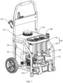
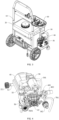
- the cleaning device includes a frame 10, a water tank 20, a water pump 30, a motor pump assembly 40, a multi-channel adapter 50, and a battery pack assembly 60.
- the water tank 20, the water pump 30, the motor pump assembly 40, the multi-channel adapter 50, and the battery pack assembly 60 are all mounted on the frame 10, and the water tank 20 is mounted on a side of the frame 10.
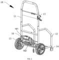
- the frame 10 includes a handle frame 11 and a supporting frame 12, where the handle frame 11 is fixedly connected to a side of the supporting frame 12, wheels 13 are mounted at a bottom of the supporting frame 12, the wheels 13 are located on a first side of the supporting frame 12 on which the handle frame 11 is mounted, and supporting legs 14 are mounted on a second side of the supporting frame 12.
- the wheels 13 With the arrangement of the wheels 13, the movement of the cleaning device is facilitated, while with the arrangement of the supporting legs 14, the cleaning device is fixed to a position without moving, so as to avoid affecting the cleaning operation due to movement.
- the water tank 20 since the water tank 20 has a relatively large volume, it is not convenient to remove the water tank for fetching water. Therefore, the water tank 20 is fixed to the frame 10 as a whole, so that the water tank 20 can be easily moved by using the wheels 13 of the cleaning device, and a water filling port of the water tank 20 is relatively large, so that it is convenient to fill the water tank 20 with water or connect an external water pipe to fill the water tank with water.
- a fixed frame 15 is further arranged on a side of the handle frame 11, and the fixed frame 15 is configured to place a cleaning tool, such as a cleaning gun, to facilitate operation by a worker.
- the frame 10 is mainly configured to store, mount, and fix various modules of the cleaning device, and provide protection therefor.
- the cleaning device is provided with the water tank 20, the handle frame 11, and the wheels 13, thereby reducing the heavy operation of manually fetching water.
- the frame 10 further includes a winding frame 16, and the winding frame 16 is mounted on a side of the supporting frame 12 on which the handle frame 11 is mounted.
- the winding frame 16 includes at least two L-shaped supporting rods spaced apart, which are labeled as a first supporting rod 161 and a second supporting rod 162, respectively.
- An end of the first supporting rod 161 is fixedly connected to the supporting frame 12, and an end of the second supporting rod 162 is movably connected to the supporting frame 12.
- the second supporting rod 162 can rotate in a direction from 0° to 90° to facilitate rapid storage and release of a power cable.
- the water tank 20 is mounted on the supporting frame 12 of the frame 10, and is located on a side close to the handle frame 11.
- the water tank 20 further includes a tank body 21, a water outlet joint (not shown), a water tank cover 23, and a water filling port.
- the water filling port is provided at a top of the tank body 21, the water tank cover 23 is mounted on the water filling port, and the water outlet joint is arranged on a sideof the tank body 21 and is close to a bottom of the tank body 21.
- the water tank 20 has a volume between 15 L and 50 L, and is fixedly connected to the frame 10.
- a water fetching method may be that water is fetched manually and then poured into the tank body 21 through the water filling port, or an external tap water pipe is connected into the tank body 21 through the water filling port, or water is pumped from an external pool by the water pump 30 provided by the cleaning device and is poured into the tank body 21 through the multi-channel adapter 50 and the water outlet joint.
- a large water tank 20 is arranged on the cleaning device as a main water source for outdoor use, so that the problem of poor work experience due to a need to frequently fetch water, which is time-consuming and laborious can be solved.
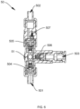
- the multi-channel adapter 50 is also mounted on the frame 10, and interfaces of the multi-channel adapter 50 are configured to connect the water outlet joint (not shown) of the water tank 20, the water pump 30, and the motor pump assembly 40, respectively.
- the multi-channel adapter 50 is further configured to connect tap water.
- the multi-channel adapter 50 includes a housing 51, and the housing 51 is provided with a plurality of water inlets and a water outlet 508. The plurality of water inlets are connected to different water sources, respectively, and the water outlet 508 is connected to a water suction port of the motor pump assembly 40.
- the water sources include tap water, water stored in the water tank 20 on the cleaning device, and water from the external pool pumped by the water pump 30.
- the water inlets include a first water inlet 501, a second water inlet 502, and a third water inlet 503.
- the first water inlet 501 is connected to the water outlet joint of the water tank 20 through a first pipeline 52 and a first pipeline joint 521, so that the water stored in the water tank 20 can be used as a water source to be supplied to the cleaning device.
- a first water filtering apparatus is arranged at one end of the first pipeline 52 connected to the water outlet joint of the water tank 20, and the first water filtering apparatus can be disassembled and cleaned, so as to clean out impurities accumulated in the water tank 20, prevent the impurities from entering the motor pump assembly 40, and prevent the motor pump assembly 40 from being damaged.
- the second water inlet 502 is connected to a water outlet of the water pump 30 through a second pipeline 53, and a water pumping pipeline 301 is further connected to a water inlet of the water pump 30.
- a first end of the water pumping pipeline 301 is connected to the water pump 30, and a water pumping joint 302 is mounted at a second end thereof.
- a second water filtering apparatus is arranged in the water pumping joint 302 to prevent impurities from entering the water pump 30 and the motor pump assembly 40, and prevent the water pump 30 and the motor pump assembly 40 from being damaged.
- the water pumping pipeline 301 is configured to be connected in the external pool, so that the water in the external pool can be used as a water source by the cleaning device, to meet use requirements for the cleaning device in various scenarios.
- the water pump 30 can directly pump the water from the external pool for use by the cleaning device, and the water in the external pool can be pumped by the water pump 30, and is directly poured, after the second pipeline 53 is manually disconnected from the multi-channel adapter 50, into the water tank 20 through the second pipeline 53 for storage, to facilitate subsequent use.
- the water pump 30 is configured to pump water in rivers, ponds, and pools into the water tank 20 through the attached water pumping pipeline 301 when it is inconvenient to fetch water from an outdoor water source, so that a user does not need a process of removing the water tank 20 to fetch water from a source, which greatly improves user experience, and can meet use requirements in various scenarios.
- the third water inlet 503 is configured to connect tap water, and the tap water is used as a water source by the cleaning device.
- the third water inlet 503 is connected to a tap of the tap water through a tap water joint 5031, and a third water filtering apparatus is arranged in the tap water joint 5031 to prevent impurities from entering the motor pump assembly 40 and prevent the motor pump assembly 40 from being damaged.
- one check valve is arranged on each water inlet channel.
- the valve can only be opened in a unidirectional direction from a water inlet end of a water inlet pipeline to the water inlet pipeline of the pump, that is, one check valve is arranged at each water inlet.
- a first check valve 504 is arranged at the first water inlet 501
- a second check valve 505 is arranged at the second water inlet 502
- a third check valve 506 is arranged at the third water inlet 503.
- Different opening pressure values are set for the first check valve 504, the second check valve 505, and the third check valve 506, so that when a different water source is used, a corresponding check valve is opened, while the remaining check valves are closed, to ensure that when the cleaning device operates by using different water sources, water inflow from different water inlets does not interfere with each other.
- the third check valve 506 at the third water inlet 503 connected to the tap water is opened, and a larger opening pressure value may be set for the water inlet check valve of this channel due to the larger inlet water pressure;
- a smaller opening pressure value is set for the water inlet check valve of this channel;
- the water pump 30 is connected to the second water inlet 502 through the second pipeline 53, and since a water outlet end of the water pump 30 also has a certain water pressure, the opening pressure value of the check valve on this water inlet channel may be set between the opening pressure values of the check valves at the first water inlet 501 and the third water inlet 503.
- an exhaust valve 507 is further mounted in the second water inlet 502 of the multi-channel adapter 50 connected to the water pump 30, that is, two check valves are provided at the second water inlet 502 of the multi-channel adapter 50 connected to the water pump 30, one of the check valves is used for exhaust gas as the exhaust valve 507 and the other is used for water inflow as the second check valve 506.
- the exhaust valve 507 does not form a stable water flow, the exhaust valve 507 is in an open state, and the inside of the valve is connected to the outside. When there is gas flow inside, the gas can be quickly discharged from here.
- the stable water flow will cause the exhaust valve 507 to be closed, allowing the water to enter the motor pump assembly 40.
- the water outlet of the water pump 30 may be connected to the water inlet of the motor pump assembly 40 through a pipeline to directly supply water to the cleaning device.
- the exhaust valve 507 can also solve the exhaust problem of a water pipe.
- An exhaust valve 507 is further designed between the water outlet of the water pump 30 and the water inlet of the multi-channel adapter 50, and the exhaust valve 507 can exhaust the air in a water pumping pipeline.
- the water pump 30 forms an initial water pressure during water pumping, so that water in a river or pond can directly enter the high-pressure water pump more quickly.
- the air originally in the longer water inlet pipeline may pass through the water pump 30 and enter a pipeline between the water pump 30 and the multi-channel adapter 50.
- an exhaust valve 507 is arranged at the second water inlet 502 of the pump, so that the air entering this pipeline can be discharged into the atmosphere through the exhaust valve 507.
- water flow entering this channel from the water pump 30 may form the inlet water pressure, so that the water inlet check valve of the multi-channel adapter 50 is opened to form a stable inlet water flow.
- the exhaust valve 507 can also exhaust in time the air in the long water inlet pipeline between the water inlet end of the water pump 30 and the water source, thereby reducing an exhaust time for the motor pump assembly 40 and shortening a high-pressure water outlet time of the motor pump assembly 40.
- the water pump 30 is preferably a direct current diaphragm pump, and the outlet water pressure of the water pump 30 is 0.3-1.0 MPa, with a flow rate of 3-5 L/min.
- the flow rate of the water pump 30 is equivalent to the high-pressure water outlet flow rate of the cleaning device, so a stable inlet water flow can be provided to the cleaning device.
- the water pump 30 when the water pump 30 is supplying water to the water tank 20, it can also ensure that the water flow of the water tank 20 is not interrupted and does not overflow.
- the check valve arranged at the water inlet connected to the water tank 20 on the multi-channel adapter 50 is opened, and the remaining check valves are in a closed state, that is, the first check valve 504 is opened, and the second check valve 505 and the third check valve 506 are closed.
- the check valve arranged at the water inlet connected to the water pump 30 on the multi-channel adapter 50 is opened, and the remaining check valves are in a closed state, that is, the second check valve 505 is opened, and the first check valve 504 and the third check valve 506 are closed.
- the check valve arranged at the water inlet connected to the tap water on the multi-channel adapter 50 is opened, and the remaining check valves are in a closed state, that is, the third check valve 506 is opened, and the first check valve 504 and the second check valve 505 are closed.
- the multi-channel adapter 50 may also be provided as a manual three-way valve, and the switching between the above water inlets may also be manually completed by using the manual three-way valve.
- the manual three-way valve includes at least two water inlets and one water outlet, where one of the water inlets is connected to the water tank 20, and the other water inlet is configured to connect the tap water or the water pump 30.
- the water tank and/or the tap water and/or the water pumped by water pump is used as the water supply source of the cleaning device, and free switching between the two water inlets in the manual three-way valve is achieved through manual switching to switch the water supply source, and the water outlet is connected to the motor pump assembly.
- One water inlet of the manual three-way valve is connected to a water outlet joint of the water tank through a pipeline, and a first water filtering apparatus is arranged at one end of the pipeline connected to the water outlet joint of the water tank.
- a motor pump assembly 40 is further mounted on the supporting frame 12 of the frame 10, and the motor pump assembly 40 is a high-pressure water outlet pump.
- the motor pump assembly 40 includes a motor 41 and a three-plunger high-pressure pump 42.
- the motor 41 is connected to the three-plunger high-pressure pump 42, and a water inlet of the three-plunger high-pressure pump 42 is connected to the water outlet of the multi-channel adapter 50, to pressurize the water in the above water source by the motor pump assembly 40 and then spray the water out from a water spray port 402 of the three-plunger high-pressure pump 42, so as to perform a cleaning operation.
- the motor 41 is an alternating current/direct current dual-purpose series-excited motor pump.
- the alternating current/direct current dual-purpose series-excited motor pump and the multi-pack battery pack assembly 60 constitute an alternating current/direct current dual-purpose cleaning device core and a direct current power source.
- the cleaning device is fixed in the supporting frame 12 and protected thereby, which solves the power source problem in use by a user in various scenarios.
- the motor 41 is a series-excited motor, and the motor can operate under the direct current power source and the alternating current power source.
- a cleaning agent suction pot assembly 70 is further mounted on the supporting frame 12 of the frame 10, the water pump 30 and the motor pump assembly 40 are located between the water tank 20 and the cleaning agent suction pot assembly 70, the cleaning agent suction pot assembly 70 is connected to a liquid suction joint 401 of the motor pump assembly 40 through a cleaning agent pipeline 701, and the liquid suction joint 401 is arranged at the water outlet of the motor pump assembly 40, and is configured to add a cleaning agent into water flow pumped by the motor pump assembly.
- the cleaning agent suction pot assembly 70 is a cleaning device cleaning agent suction water tank configured by this cleaning device, and a cleaning agent or other liquid for enhancing the cleaning effect is stored therein.
- the cleaning agent for cleaning is conveyed to the motor pump assembly 40 through the cleaning agent pipeline 701 provided in the motor pump assembly 40 and the cleaning agent suction pot assembly 70, so as to meet requirements of the user for cleaning a dirty environment.
- a battery pack assembly 60 is further mounted on the frame 10, and the battery pack assembly 60 is composed of two or more detachable battery packs.
- the supply voltage is converted into the optimal operating voltage of the motor pump assembly by series and/or parallel connection between the plurality of detachable battery packs, so that direct current power that is the same as alternating current voltage can be provided to the motor pump to ensure that the performance of the cleaning device is equivalent during operation.
- at least two battery packs of the battery packs may be connected in series to form one group, and then all groups of battery packs are connected in parallel, so as to convert the supply voltage into the optimal operating voltage of the motor pump assembly 40, to provide the direct current power that is the same as alternating current voltage to the motor pump assembly 40.
- the capacity of the direct current power is increased, so that the cleaning device can have a longer battery life in the case of a high voltage.
- the battery packs are detachable to facilitate quick and convenient replacement, which further enhances the battery life of the cleaning device.
- the battery pack assembly 60 includes a battery pack mounting box 61, and a plurality of battery pack accommodating cavities 601 are provided in the battery pack mounting box 61 to accommodate and mount a plurality of the battery packs 62.
- the battery pack accommodating cavities 601 are distributed in a straight line in the battery pack mounting box 61, and certainly, may also be distributed in other ways, such as rectangular distribution and triangular distribution.
- the battery pack assembly 60 is mounted on the frame 10 at a position close to the middle to improve the stability of the mechanism.
- the battery pack mounting box 61 is detachably mounted on the frame 10, and a spring 602 and a terminal insert 603 are mounted at a bottom of the battery pack accommodating cavity 601.
- the terminal insert 603 is configured to electrically connect a device body not shown when the battery pack assembly 60 supplies power to the device body.
- a battery pack limiting mechanism 63 is arranged on a side of a top of the battery pack accommodating cavity 601, and the battery pack limiting mechanism 63 is configured to fix the battery pack 62.
- the battery pack limiting mechanism 63 includes a mounting base 631, a limiting member 632, and a spring member 633, where the mounting base 631 is mounted on a side of the top of the battery pack accommodating cavity 601, or may be integrally formed with the battery pack mounting box 61.
- the limiting member 632 is rotatably connected to the mounting base 631 by a rotating shaft, and the spring member 633 is sleeved on the rotating shaft, is located between the limiting member 632 and the rotating shaft, and is configured to provide a pressure to the limiting member 632, so that the limiting member limits the battery pack 62 to fix the battery pack 62.
- a terminal interface 621 is provided at a bottom of the battery pack 62 to connect the terminal insert 603, so as to provide power to the motor pump assembly 40.
- a limiting structure 622 matching the limiting member 632 is arranged on a side of the battery pack 62 to fixedly mount the battery pack 62.
- the battery pack 62 is mounted, the battery pack 62 is inserted into the battery pack accommodating cavity 601, and the spring 602 is compressed until the terminal insert 603 is inserted into the terminal interface 621, and the battery pack 62 is fixedly mounted under cooperation of the battery pack limiting mechanism 63 and the limiting structure 622.
- the battery pack 62 needs to be disassembled or replaced, by pressing the limiting member 632, the limiting member 632 is disengaged from the limiting structure 622, so that the battery pack 62 is not limited. Under an elastic force of the spring 602, the battery pack 62 is ejected to facilitate disassembly or replacement.
- an electric quantity display portion for displaying a state of charge of the battery pack assembly 60 is arranged on the battery pack assembly 60.
- the electric quantity display portion is located in the front of the battery pack assembly 60.
- a battery pack group of three 40 V battery packs is shown, and may form a direct current voltage output of 120 V by connecting the three battery packs in series.
- a battery pack group of two 60 V battery packs, two 56 V battery packs, six 20 V battery packs, or the like may form a voltage output of 120 V or close to 120 V.
- the direct current voltage of 120 V or close to 120 V is equivalent to the alternating current voltage of 120 V in North America and other places, and the cleaning device can achieve almost equivalent power output when operating in alternating current/direct current, so as to achieve an equivalent cleaning effect.
- a battery pack group of 220 V to 240 V may be formed by three 80 V battery packs, four 60 V battery packs, or the like to be used for the cleaning device. It should be noted that provided that a difference between the direct current voltage and the alternating current voltage is within 20%, the cleaning device with a product power output within 20% may be regarded as having a similar function to this cleaning device.
- a plurality of battery packs may be connected in series and then connected in parallel.
- two 60 V batteries are connected in series first and then connected in parallel with other two batteries connected in series, so that the electric capacity of direct current can be doubled at the same alternating current voltage, and the working time of the cleaning device can be doubled, thus prolonging the battery life of the cleaning device.
- the cleaning device is further provided with a power interface, and the power interface is externally connected to a power source by a power cable to provide alternating current power.
- the battery pack assembly 60 may provide direct current power to the motor pump assembly 40, or alternating current power may be provided to the motor pump assembly 40 by a power cable on the winding frame 16, and the voltage of the direct current power is equivalent to that of the alternating current power, so that the cleaning device achieves almost equivalent power output when operating in alternating current/direct current, so as to achieve an equivalent cleaning effect.
- the cleaning device can control the switching between the alternating current power and the direct current power by an alternating current/direct current control module 80.
- the alternating current/direct current control module 80 is mounted on the frame 10, and the alternating current/direct current control module 80 includes an alternating current/direct current power transfer switch 81 and a controller 82; the alternating current/direct current transfer switch 81 is electrically connected to a battery pack assembly 60 and an external power source, where the battery pack assembly 60 provides direct current power, the external power source provides alternating current power, and the alternating current/direct current power transfer switch 81 is configured to control and switch between the alternating current power and the direct current power; and the controller 82 is configured to protect a circuit, and a supply voltage provided by the battery pack assembly 60 and the external power source by using the controller 82 is consistent with an optimal operating voltage of the motor pump assembly 40.
- the alternating current/direct current control module 80 may directly connect the alternating current power source by using the alternating current/direct current power transfer switch 81, or integrate a battery pack group connected in series, parallel, or series-parallel into a direct current power source to supply power to the cleaning device.
- a line of the direct current power source may also be led out by the battery pack group 70 to supply power to the water pump 30.
- the alternating current/direct current power transfer switch 81 is configured to operatively control on-off of a direct current conduction loop and on-off of an alternating current conduction loop.
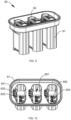
- An outline view of the alternating current/direct current power transfer switch is shown in FIG. 13, and FIG. 14 is a sectional view of the alternating current/direct current power transfer switch 81 from different angles.
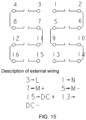
- a diagram of an electrical principle of the alternating current/direct current power transfer switch is shown in FIG. 15 .
- the switch is formed by combining multilayer superimposed switches, and a knob joystick 811 is provided in the middle to switch an AC/DC power-on state.
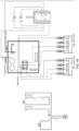
- FIG. 16 is a diagram showing wiring between the alternating current/direct current power transfer switch 81 and the controller 82.
- FIG. 16 also shows electrical connection between the battery pack group and the controller, and the figure shows that two battery packs are connected in series to the controller 82.
- the controller realizes power management and protection of the cleaning device only in the direct current power supply state.
- a diagram of an electrical principle of the controller is shown in FIG. 17 , and the figure embodies a specific principle of controlling a power source.
- the present disclosure provides a cleaning device, which can use an alternating current power source and a direct current power source.
- the alternating current/direct current dual-purpose cleaning device is designed to take into account various use scenarios for the user with or without an alternating current power source, and the cleaning device can operate in the optimal performance state when the alternating current power source supplies power, thereby providing a good cleaning effect.
- the direct current power source operates, since the voltage of the battery pack group is equivalent to the alternating current voltage, its use performance is basically equivalent, and ideal results can also be achieved.
- the cleaning device also takes into account various use scenarios with or without tap water supply for the user, and operating modes of a plurality of inlet water sources and normal switching of various modes are designed, thus greatly improving use convenience for the user.
- the present disclosure solves the problems that the cleaning effect is poor because of a low direct current voltage when the user operates in direct current in the past; the electric capacity is small, and the battery life is short.
- the present disclosure also solves the problem of how to continue to use water and electricity when it is inconvenient to use tap water, such as outdoors or at a wharf, thereby effectively improving user experience.
Landscapes
- Engineering & Computer Science (AREA)
- Chemical & Material Sciences (AREA)
- Chemical Kinetics & Catalysis (AREA)
- Electrochemistry (AREA)
- General Chemical & Material Sciences (AREA)
- Mechanical Engineering (AREA)
- General Engineering & Computer Science (AREA)
- Life Sciences & Earth Sciences (AREA)
- Biophysics (AREA)
- Computer Hardware Design (AREA)
- Cleaning By Liquid Or Steam (AREA)
Applications Claiming Priority (9)
| Application Number | Priority Date | Filing Date | Title |
|---|---|---|---|
| CN202121770809.4U CN216323629U (zh) | 2021-07-30 | 2021-07-30 | 一种用于清洗机的多通道转接装置及清洗机 |
| CN202121757727.6U CN215613549U (zh) | 2021-07-30 | 2021-07-30 | 一种清洗机 |
| CN202121772739.6U CN215696223U (zh) | 2021-07-30 | 2021-07-30 | 一种清洗机 |
| CN202121757730.8U CN216324044U (zh) | 2021-07-30 | 2021-07-30 | 一种用于清洗机的供能系统及清洗机 |
| CN202121770856.9U CN216297258U (zh) | 2021-07-30 | 2021-07-30 | 一种清洗机 |
| CN202110868645.7A CN113546903B (zh) | 2021-07-30 | 2021-07-30 | 一种用于清洗机的驱动组件及清洗机 |
| CN202110879751.5A CN113578837B (zh) | 2021-07-30 | 2021-07-30 | 一种清洗机 |
| CN202110868474.8A CN113560257A (zh) | 2021-07-30 | 2021-07-30 | 一种清洗机 |
| PCT/CN2022/106153 WO2023005698A1 (fr) | 2021-07-30 | 2022-07-18 | Machine de nettoyage |
Publications (2)
| Publication Number | Publication Date |
|---|---|
| EP4368302A1 true EP4368302A1 (fr) | 2024-05-15 |
| EP4368302A4 EP4368302A4 (fr) | 2024-10-23 |
Family
ID=85086258
Family Applications (1)
| Application Number | Title | Priority Date | Filing Date |
|---|---|---|---|
| EP22848303.8A Pending EP4368302A4 (fr) | 2021-07-30 | 2022-07-18 | Machine de nettoyage |
Country Status (3)
| Country | Link |
|---|---|
| US (1) | US20240149307A1 (fr) |
| EP (1) | EP4368302A4 (fr) |
| WO (1) | WO2023005698A1 (fr) |
Family Cites Families (24)
| Publication number | Priority date | Publication date | Assignee | Title |
|---|---|---|---|---|
| US6189811B1 (en) * | 1999-11-15 | 2001-02-20 | David Owen Rudy | Portable water-pumping system |
| US20050145270A1 (en) * | 2003-12-31 | 2005-07-07 | Ray R. K. | Pressure washer with injector |
| NZ582896A (en) * | 2009-02-05 | 2011-12-22 | John Charles Turner | A modular cleaning system adaptable to perform a number of cleaning tasks that can recycle water used |
| US9316216B1 (en) * | 2012-03-28 | 2016-04-19 | Pumptec, Inc. | Proportioning pump, control systems and applicator apparatus |
| GB201321495D0 (en) * | 2013-12-05 | 2014-01-22 | Agco Netherlands Bv | Casting for pump system on agricultural sprayer |
| CN203750901U (zh) * | 2013-12-23 | 2014-08-06 | 常州格力博有限公司 | 交直流两用清洗机 |
| CN204320708U (zh) * | 2014-11-25 | 2015-05-13 | 常州格力博有限公司 | 泵头外露的清洗机 |
| CN205344845U (zh) * | 2016-01-22 | 2016-06-29 | 深圳欧博特雨水科技股份有限公司 | 一种雨水洗车机 |
| MX2018007783A (es) * | 2016-02-22 | 2019-09-06 | Tti Macao Commercial Offshore Ltd | Sistema de hidrolavadora modular, su metodo y kit. |
| US20170304873A1 (en) * | 2016-04-20 | 2017-10-26 | Karcher North America, Inc. | Electric pressure washer |
| EP3552721A4 (fr) * | 2016-12-06 | 2020-08-12 | Positec Power Tools (Suzhou) Co., Ltd | Machine de nettoyage haute pression et ensemble machine de nettoyage haute pression |
| WO2018140753A1 (fr) * | 2017-01-27 | 2018-08-02 | Briggs & Stratton Corporation | Nettoyeur a haute pression alimentée par batterie |
| US20180221899A1 (en) * | 2017-02-03 | 2018-08-09 | Mi-T-M Corporation | System and apparatus for an electric pressure washer |
| DE102017206500A1 (de) * | 2017-04-18 | 2018-10-18 | Robert Bosch Gmbh | Druckreinigungsvorrichtung mit einer Druckerzeugungseinheit |
| US20190388918A1 (en) * | 2018-06-25 | 2019-12-26 | Wessol, Llc | Variable pressure sprayer |
| EP3745844A1 (fr) * | 2018-02-02 | 2020-12-09 | Hydroside Systems Llc | Moteur d'entraînement d'irrigation agricole à charge hydroélectrique et système mobile d'irrigation agricole le comprenant |
| CN110721843A (zh) * | 2018-06-29 | 2020-01-24 | 苏州宝时得电动工具有限公司 | 清洗设备组件 |
| CN213468782U (zh) * | 2019-05-10 | 2021-06-18 | 南京德朔实业有限公司 | 多功能清洗机 |
| CN111933858B (zh) * | 2020-08-27 | 2025-06-27 | 格力博(江苏)股份有限公司 | 电池包释放结构 |
| CN113546903B (zh) * | 2021-07-30 | 2023-03-14 | 格力博(江苏)股份有限公司 | 一种用于清洗机的驱动组件及清洗机 |
| CN216297258U (zh) * | 2021-07-30 | 2022-04-15 | 格力博(江苏)股份有限公司 | 一种清洗机 |
| CN216323629U (zh) * | 2021-07-30 | 2022-04-19 | 格力博(江苏)股份有限公司 | 一种用于清洗机的多通道转接装置及清洗机 |
| CN113560257A (zh) * | 2021-07-30 | 2021-10-29 | 格力博(江苏)股份有限公司 | 一种清洗机 |
| CN216324044U (zh) * | 2021-07-30 | 2022-04-19 | 格力博(江苏)股份有限公司 | 一种用于清洗机的供能系统及清洗机 |
-
2022
- 2022-07-18 WO PCT/CN2022/106153 patent/WO2023005698A1/fr not_active Ceased
- 2022-07-18 EP EP22848303.8A patent/EP4368302A4/fr active Pending
-
2024
- 2024-01-15 US US18/412,622 patent/US20240149307A1/en active Pending
Also Published As
| Publication number | Publication date |
|---|---|
| WO2023005698A1 (fr) | 2023-02-02 |
| US20240149307A1 (en) | 2024-05-09 |
| EP4368302A4 (fr) | 2024-10-23 |
Similar Documents
| Publication | Publication Date | Title |
|---|---|---|
| CN203209349U (zh) | 高压洗涤装置 | |
| CN104114294A (zh) | 高压清洗设备以及适配器 | |
| CN113546903B (zh) | 一种用于清洗机的驱动组件及清洗机 | |
| CN113578837B (zh) | 一种清洗机 | |
| CN216297258U (zh) | 一种清洗机 | |
| CN216324044U (zh) | 一种用于清洗机的供能系统及清洗机 | |
| EP4368302A1 (fr) | Machine de nettoyage | |
| WO2024012447A1 (fr) | Machine de nettoyage | |
| CN113560257A (zh) | 一种清洗机 | |
| EP3991854A1 (fr) | Systèmes de pulvérisation portables et leurs procédés de fabrication et d'utilisation | |
| CN216323629U (zh) | 一种用于清洗机的多通道转接装置及清洗机 | |
| CN114054408B (zh) | 配备有电池的压力清洗机 | |
| CN210815840U (zh) | 手持式高压清洗机 | |
| GB2595179A (en) | Cordless appliance, such as a surface cleaning apparatus, and a charging unit therefor | |
| CN108233441A (zh) | 电源适配器及交直流电源驱动的工具 | |
| US20250108396A1 (en) | Spray gun and control method of spray gun | |
| CN215613549U (zh) | 一种清洗机 | |
| WO2020011153A1 (fr) | Dispositif de lavage haute pression portatif | |
| CN215696223U (zh) | 一种清洗机 | |
| CN210304202U (zh) | 手持式高压清洗机 | |
| CN215174948U (zh) | 一种蒸汽熨斗的蒸汽发生装置 | |
| CN218636133U (zh) | 小型洗牙器和电动牙刷二合一装置 | |
| CN201669242U (zh) | 清洗机与盛水容器组合结构 | |
| CN201231196Y (zh) | 便携直流清洗机 | |
| CN217664029U (zh) | 一种船舱内便携充电式可调水泵锂电池增压水枪及系统 |
Legal Events
| Date | Code | Title | Description |
|---|---|---|---|
| STAA | Information on the status of an ep patent application or granted ep patent |
Free format text: STATUS: THE INTERNATIONAL PUBLICATION HAS BEEN MADE |
|
| PUAI | Public reference made under article 153(3) epc to a published international application that has entered the european phase |
Free format text: ORIGINAL CODE: 0009012 |
|
| STAA | Information on the status of an ep patent application or granted ep patent |
Free format text: STATUS: REQUEST FOR EXAMINATION WAS MADE |
|
| 17P | Request for examination filed |
Effective date: 20240205 |
|
| AK | Designated contracting states |
Kind code of ref document: A1 Designated state(s): AL AT BE BG CH CY CZ DE DK EE ES FI FR GB GR HR HU IE IS IT LI LT LU LV MC MK MT NL NO PL PT RO RS SE SI SK SM TR |
|
| A4 | Supplementary search report drawn up and despatched |
Effective date: 20240923 |
|
| RIC1 | Information provided on ipc code assigned before grant |
Ipc: F04B 41/02 20060101ALI20240917BHEP Ipc: F04B 17/06 20060101ALI20240917BHEP Ipc: F04B 17/03 20060101ALI20240917BHEP Ipc: A47L 11/40 20060101ALI20240917BHEP Ipc: A47L 11/34 20060101ALI20240917BHEP Ipc: H01M 50/269 20210101ALI20240917BHEP Ipc: H01M 50/244 20210101ALI20240917BHEP Ipc: H02J 7/00 20060101ALI20240917BHEP Ipc: F04B 53/06 20060101ALI20240917BHEP Ipc: F04B 53/10 20060101ALI20240917BHEP Ipc: F04B 53/20 20060101ALI20240917BHEP Ipc: H02M 1/10 20060101ALI20240917BHEP Ipc: H02J 9/06 20060101ALI20240917BHEP Ipc: B08B 13/00 20060101ALI20240917BHEP Ipc: B08B 3/08 20060101ALI20240917BHEP Ipc: B08B 3/02 20060101AFI20240917BHEP |
|
| DAV | Request for validation of the european patent (deleted) | ||
| DAX | Request for extension of the european patent (deleted) |