EP4368492B1 - Wasserfahrzeugantriebssystem und wasserfahrzeug mit dem wasserfahrzeugantriebssystem - Google Patents
Wasserfahrzeugantriebssystem und wasserfahrzeug mit dem wasserfahrzeugantriebssystem Download PDFInfo
- Publication number
- EP4368492B1 EP4368492B1 EP23208424.4A EP23208424A EP4368492B1 EP 4368492 B1 EP4368492 B1 EP 4368492B1 EP 23208424 A EP23208424 A EP 23208424A EP 4368492 B1 EP4368492 B1 EP 4368492B1
- Authority
- EP
- European Patent Office
- Prior art keywords
- bow
- command
- translation
- watercraft
- turning
- Prior art date
- Legal status (The legal status is an assumption and is not a legal conclusion. Google has not performed a legal analysis and makes no representation as to the accuracy of the status listed.)
- Active
Links
Images


Classifications
-
- B—PERFORMING OPERATIONS; TRANSPORTING
- B63—SHIPS OR OTHER WATERBORNE VESSELS; RELATED EQUIPMENT
- B63H—MARINE PROPULSION OR STEERING
- B63H25/00—Steering; Slowing-down otherwise than by use of propulsive elements; Dynamic anchoring, i.e. positioning vessels by means of main or auxiliary propulsive elements
- B63H25/46—Steering or dynamic anchoring by jets or by rudders carrying jets
-
- G—PHYSICS
- G05—CONTROLLING; REGULATING
- G05D—SYSTEMS FOR CONTROLLING OR REGULATING NON-ELECTRIC VARIABLES
- G05D1/00—Control of position, course, altitude or attitude of land, water, air or space vehicles, e.g. using automatic pilots
- G05D1/02—Control of position or course in two dimensions
- G05D1/0206—Control of position or course in two dimensions specially adapted to water vehicles
-
- B—PERFORMING OPERATIONS; TRANSPORTING
- B63—SHIPS OR OTHER WATERBORNE VESSELS; RELATED EQUIPMENT
- B63H—MARINE PROPULSION OR STEERING
- B63H25/00—Steering; Slowing-down otherwise than by use of propulsive elements; Dynamic anchoring, i.e. positioning vessels by means of main or auxiliary propulsive elements
- B63H25/02—Initiating means for steering, for slowing down, otherwise than by use of propulsive elements, or for dynamic anchoring
- B63H25/04—Initiating means for steering, for slowing down, otherwise than by use of propulsive elements, or for dynamic anchoring automatic, e.g. reacting to compass
-
- B—PERFORMING OPERATIONS; TRANSPORTING
- B63—SHIPS OR OTHER WATERBORNE VESSELS; RELATED EQUIPMENT
- B63H—MARINE PROPULSION OR STEERING
- B63H25/00—Steering; Slowing-down otherwise than by use of propulsive elements; Dynamic anchoring, i.e. positioning vessels by means of main or auxiliary propulsive elements
- B63H25/42—Steering or dynamic anchoring by propulsive elements; Steering or dynamic anchoring by propellers used therefor only; Steering or dynamic anchoring by rudders carrying propellers
-
- B—PERFORMING OPERATIONS; TRANSPORTING
- B63—SHIPS OR OTHER WATERBORNE VESSELS; RELATED EQUIPMENT
- B63H—MARINE PROPULSION OR STEERING
- B63H5/00—Arrangements on vessels of propulsion elements directly acting on water
- B63H5/07—Arrangements on vessels of propulsion elements directly acting on water of propellers
- B63H5/08—Arrangements on vessels of propulsion elements directly acting on water of propellers of more than one propeller
-
- B—PERFORMING OPERATIONS; TRANSPORTING
- B63—SHIPS OR OTHER WATERBORNE VESSELS; RELATED EQUIPMENT
- B63H—MARINE PROPULSION OR STEERING
- B63H20/00—Outboard propulsion units, e.g. outboard motors or Z-drives; Arrangements thereof on vessels
- B63H20/08—Means enabling movement of the position of the propulsion element, e.g. for trim, tilt or steering; Control of trim or tilt
-
- B—PERFORMING OPERATIONS; TRANSPORTING
- B63—SHIPS OR OTHER WATERBORNE VESSELS; RELATED EQUIPMENT
- B63H—MARINE PROPULSION OR STEERING
- B63H20/00—Outboard propulsion units, e.g. outboard motors or Z-drives; Arrangements thereof on vessels
- B63H2020/003—Arrangements of two, or more outboard propulsion units
-
- B—PERFORMING OPERATIONS; TRANSPORTING
- B63—SHIPS OR OTHER WATERBORNE VESSELS; RELATED EQUIPMENT
- B63H—MARINE PROPULSION OR STEERING
- B63H25/00—Steering; Slowing-down otherwise than by use of propulsive elements; Dynamic anchoring, i.e. positioning vessels by means of main or auxiliary propulsive elements
- B63H25/02—Initiating means for steering, for slowing down, otherwise than by use of propulsive elements, or for dynamic anchoring
- B63H2025/026—Initiating means for steering, for slowing down, otherwise than by use of propulsive elements, or for dynamic anchoring using multi-axis control levers, or the like, e.g. joysticks, wherein at least one degree of freedom is employed for steering, slowing down, or dynamic anchoring
-
- B—PERFORMING OPERATIONS; TRANSPORTING
- B63—SHIPS OR OTHER WATERBORNE VESSELS; RELATED EQUIPMENT
- B63H—MARINE PROPULSION OR STEERING
- B63H5/00—Arrangements on vessels of propulsion elements directly acting on water
- B63H5/07—Arrangements on vessels of propulsion elements directly acting on water of propellers
- B63H5/14—Arrangements on vessels of propulsion elements directly acting on water of propellers characterised by being mounted in non-rotating ducts or rings, e.g. adjustable for steering purpose
-
- B—PERFORMING OPERATIONS; TRANSPORTING
- B63—SHIPS OR OTHER WATERBORNE VESSELS; RELATED EQUIPMENT
- B63H—MARINE PROPULSION OR STEERING
- B63H5/00—Arrangements on vessels of propulsion elements directly acting on water
- B63H5/07—Arrangements on vessels of propulsion elements directly acting on water of propellers
- B63H5/16—Arrangements on vessels of propulsion elements directly acting on water of propellers characterised by being mounted in recesses; with stationary water-guiding elements; Means to prevent fouling of the propeller, e.g. guards, cages or screens
Definitions
- the present invention relates to a watercraft propulsion system, and a watercraft including the watercraft propulsion system.
- US 2017/0305520 A1 discloses a watercraft maneuvering system including two engines that respectively rotate port-side and starboard-side forward/reverse propellers, and a side thruster that generates a lateral propulsive force.
- a watercraft maneuvering operation is performed by changing the directions of water jets generated by the forward/reverse propellers by means of rudders connected to a steering wheel and by operating a joystick lever.
- the forward/reverse propellers and the side thruster are controlled by operating the joystick lever such that a lateral movement and an oblique movement can be achieved.
- calibration for cancellation of a rotation moment in the lateral movement and the oblique movement is also described.
- US 2020/331578 A1 relates to a propulsion system for a vessel equipped with two outboard motors located on the hull and a bow thruster provided at a bow of the vessel.
- the vessel may be operated so as to perform a lateral movement, wherein the outboard motors are driven in opposing directions, in addition to the bow thruster.
- WO 2020/069750 A1 and US 2014/046515 A1 describe a watercraft including two outboard motors and a bow thruster, wherein the watercraft may perform a lateral movement by operating said component.
- preferred embodiments of the present invention provide watercraft propulsion systems and watercraft, each of which have a calibration mode in which propulsion devices provided on the stern of a hull can be properly steered for the translation or the like of the hull.
- a watercraft propulsion system according to claim 1 is provided.
- a control operation is performed according to the translation watercraft maneuvering mode for the translation of the hull by utilizing the propulsive force of the bow thruster and the propulsive forces of the at least two propulsion devices provided on the stern.
- the steering angles of the at least two stern propulsion devices are controlled so that the propulsive force action lines of the at least two propulsion devices cross each other in the hull, and one of the at least two propulsion devices is driven forward and another of the at least two propulsion devices is driven in reverse.
- the resultant propulsive force of the at least two propulsion devices acts on the hull at the intersection of the propulsive force action lines, and applies a lateral propulsive force component to the hull laterally of the hull.
- a balance between a bow turning moment to be applied to the hull by the resultant propulsive force and a bow turning moment to be applied to the hull by the propulsive force of the bow thruster is properly adjusted to achieve the translation of the hull.
- the controller is configured or programmed to control the bow thruster and the at least two propulsion devices according to the translation command and the bow turning command applied by the translation/bow turning operator in the calibration mode.
- the controller is configured or programmed to increase the output of the bow thruster when the bow turning command is a bow turning promoting command that commands bow turning in a direction indicated by the translation command, and to reduce the absolute values of the steering angles of the at least two propulsion devices (or to narrow an angle defined between the at least two propulsion devices) when the bow turning promoting command is still applied even after the output of the bow thruster reaches its upper limit.
- the bow turning of the hull is promoted by increasing the output of the bow thruster when the bow turning promoting command that commands the bow turning in the direction indicated by the translation command is applied.
- the absolute values of the steering angles of the at least two propulsion devices are reduced to further promote the bow turning.
- the absolute values of the steering angles of the stern propulsion devices are reduced. Therefore, the proper translation state of the hull can be reliably achieved.
- the absolute values of the steering angles can be maximized (the angle defined between the at least two propulsion devices can be expanded). Therefore, the calibration can be performed so as to efficiently utilize the lateral component of the resultant force of the propulsive forces generated by the stern propulsion devices.
- the controller is configured or programmed to control the bow thruster and the at least two propulsion devices according to the translation command and the bow turning command applied by the translation/bow turning operator in the calibration mode.
- the controller is configured or programmed to increase the absolute values of the steering angles of the at least two propulsion devices when the bow turning command is a bow turning reduction command that commands bow turning in a direction opposite to the direction indicated by the translation command, and to reduce the output of the bow thruster when the bow turning reduction command is still applied even after the absolute values of the steering angles reach their upper limit.
- the bow turning of the hull is reduced by increasing the absolute values of the steering angles of the at least two propulsion devices when the bow turning reduction command that commands the bow turning in the direction opposite to the direction indicated by the translation command is applied.
- the output of the bow thruster is reduced to further reduce the bow turning.
- the absolute values of the steering angles can be maximized. Therefore, the calibration can be performed so as to efficiently utilize the lateral component of the resultant force of the propulsive forces generated by the stern propulsion devices.
- the watercraft propulsion system further includes a calibration ending operator to be operated by the user to end the calibration.
- the controller is configured or programmed to generate a calibration value based on the control states of the bow thruster and the at least two propulsion devices when the calibration ending operator is operated, and to store the calibration value in a memory.
- the control operation can be performed according to the translation watercraft maneuvering mode by utilizing the calibration value thus stored in the memory.
- the calibration value includes translation steering angles to which the steering angles of the at least two propulsion devices are to be set in the translation watercraft maneuvering mode, a reference ratio that indicates the ratio of the output of the bow thruster to the lateral component of a target thrust corresponding to the translation command applied by the translation/bow turning operator, and a forward/reverse thrust ratio that indicates a ratio between the propulsive force of one of the at least two propulsion devices driven forward and the propulsive force of another of the at least two propulsion devices driven in reverse.
- the controller is configured or programmed to control the output of the bow thruster, the steering angles of the at least two propulsion devices, and the propulsive forces of the at least two propulsion devices based on the calibration value when the translation command is applied by the translation/bow turning operator in the translation watercraft maneuvering mode.
- the control operation for the translation watercraft maneuvering mode can be performed based on the calibration value.
- the controller is configured or programmed to increase the output of the bow thruster, and reduce the absolute values of the steering angles of the propulsion devices when a bow turning command that commands the bow turning in the direction indicated by the translation command is applied by the translation/bow turning operator in the translation watercraft maneuvering mode.
- the controller is configured or programmed to reduce the output of the bow thruster and increase the absolute values of the steering angles of the propulsion devices when a bow turning command that commands the bow turning in the direction opposite to the direction indicted by the translation command is applied by the translation/bow turning operator in the translation watercraft maneuvering mode.
- the control operation to be performed in the translation watercraft maneuvering mode is different from that to be performed in the calibration mode.
- the output of the bow thruster and the absolute values of the steering angles of the stern propulsion devices are simultaneously increased or reduced according to the bow turning command.
- the bow turning behavior can be properly achieved in response to the bow turning command.
- a watercraft having an excellent maneuverability can be provided.
- the watercraft propulsion system further includes an upper output limit setter to be operated by the user to set the upper limit of the output of the bow thruster.
- Calibration of the translation watercraft maneuvering mode is preferably performed based on the upper limit of the output of the bow thruster thus set.
- the calibration can be properly performed according to the setting of the upper limit of the output.
- Another preferred embodiment of the present invention provides a watercraft including a hull and a watercraft propulsion system on the hull and including any of the aforementioned features.
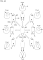
- FIG. 1 is a plan view showing an exemplary construction of a watercraft 1 mounted with a watercraft propulsion system 100 according to a preferred embodiment of the present invention.
- the watercraft 1 includes a hull 2, a bow thruster BT provided at the bow of the hull 2 and able to generate a lateral propulsive force, and outboard motors OM (examples of the propulsion device) provided on the stern 3 of the hull 2 and each having a variable steering angle.
- a plurality of outboard motors OM more specifically, two outboard motors OM are provided on the stern 3.
- the two outboard motors OM are disposed side by side transversely of the hull 2 on the stern 3.
- starboard-side outboard motor OMs one of the outboard motors OM disposed rightward relative to the other outboard motor OM
- the other outboard motor OM disposed leftward relative to the one outboard motor OM is referred to as "port-side outboard motor OMp.”
- the starboard-side outboard motor OMs is disposed on the right side of a center line 2a extending anteroposteriorly of the hull 2
- the port-side outboard motor OMp is disposed on the left side of the center line 2a. More specifically, the starboard-side outboard motor OMs and the port-side outboard motor OMp are disposed symmetrically with respect to the center line 2a.
- the outboard motors OM each include a propeller 20 located underwater, and are each configured to generate a propulsive force by the rotation of the propeller 20 and apply the propulsive force to the hull 2.
- the outboard motors OM are each attached to the stern 3 pivotably leftward and rightward such that the direction of the propulsive force generated by the propeller 20 is changed leftward and rightward.
- the steering angle is defined, for example, as an angle between the direction of the propulsive force generated by the propeller 20 and an anteroposterior reference direction parallel to the center line 2a.
- the outboard motors OM are each configured to be pivoted leftward and rightward by a steering mechanism 26 thereof (see FIG. 2 ) to change the steering angle.
- the steering angle When the propulsive force direction is parallel to the anteroposterior direction, the steering angle is zero. When the rear end of the outboard motor OM is directed rightward, the steering angle may be expressed with a positive sign. When the rear end of the outboard motor OM is directed leftward, the steering angle may be expressed with a negative sign.
- the bow thruster BT includes a propeller 40 disposed in a tubular tunnel 41 extending through the bow portion of the hull 2 transversely of the hull 2.
- the propeller 40 is rotatable in a forward rotation direction and a reverse rotation direction, i.e., is bidirectionally rotatable such that the bow thruster BT can apply a rightward or leftward propulsive force to the hull 2.
- the direction of the propulsive force to be generated by the bow thruster BT cannot be set to a direction other than the rightward direction and the leftward direction.
- a usable space 4 for passengers is provided inside the hull 2.
- a helm seat 5 is provided in the usable space 4.
- a steering wheel 6, a remote control lever 7, a joystick 8, a gauge 9 (display panel) and the like are provided in association with the helm seat 5.
- the steering wheel 6 is an operator to be operated by a user (an operator) to change the course of the watercraft 1.
- the remote control lever 7 is an operator to be operated by the user to change the magnitudes (outputs) and the directions (forward or reverse directions) of the propulsive forces of the outboard motors OM, and corresponds to an acceleration operator.
- the joystick 8 is an operator to be operated instead of the steering wheel 6 and the remote control lever 7 by the user during a watercraft maneuvering operation.
- An operator 45 (see FIG. 2 ) dedicated for the operation of the bow thruster BT may be provided in addition to the aforementioned operators.
- FIG. 2 is a block diagram showing the configuration of the watercraft propulsion system 100 provided in the watercraft 1 by way of example.
- the watercraft propulsion system 100 includes the two outboard motors OM and the bow thruster BT.
- the outboard motors OM may each be an engine outboard motor or an electric outboard motor.
- the outboard motors OM are engine outboard motors by way of example.
- the outboard motors OM each include an engine ECU (Electronic Control Unit) 21, a steering ECU 22, an engine 23, a shift mechanism 24, a propeller 20, the steering mechanism 26 and the like. Power generated by the engine 23 is transmitted to the propeller 20 via the shift mechanism 24.
- the steering mechanism 26 is configured to pivot the body of the outboard motor OM leftward and rightward with respect to the hull 2 (see FIG. 1 ) to change the direction of the propulsive force generated by the outboard motor OM leftward and rightward.
- the shift mechanism 24 is configured to select a shift position from a forward shift position, a reverse shift position, and a neutral shift position.
- the propeller 20 With the shift position set to the forward shift position, the propeller 20 is rotated in a forward rotation direction by the transmission of the rotation of the engine 23 such that the outboard motor OM is brought into a forward drive state to generate a forward propulsive force.
- the shift position set to the reverse shift position the propeller 20 is rotated in a reverse rotation direction by the transmission of the rotation of the engine 23 such that the outboard motor OM is brought into a reverse drive state to generate a reverse propulsive force.
- the shift position set to the neutral shift position the power transmission between the engine 23 and the propeller 20 is interrupted such that the outboard motor OM is brought into an idling state.
- the outboard motors OM each further include a throttle actuator 27 and a shift actuator 28, which are controlled by the engine ECU 21.
- the throttle actuator 27 is an electric actuator (typically including an electric motor) that actuates the throttle valve (not shown) of the engine 23.
- the shift actuator 28 actuates the shift mechanism 24.
- the outboard motors OM each further include a steering actuator 25 to be controlled by the steering ECU 22.
- the steering actuator 25 is the drive source of the steering mechanism 26, and typically includes an electric motor.
- the steering actuator 25 may include a hydraulic device of electric pump type.
- the bow thruster BT includes the propeller 40, an electric motor 42 that drives the propeller 40, and a motor controller 43 that controls the electric motor 42.
- the watercraft propulsion system 100 further includes a main controller 50.
- the main controller 50 includes a processor 50a and a memory 50b, and is configured so that the processor 50a executes a program stored in the memory 50b to perform a plurality of functions.
- the main controller 50 is connected to an onboard network 55 (CAN: Control Area Network) provided in the hull 2.
- a remote control unit 17, two remote control ECUs 51, a joystick unit 18, a GPS (Global Positioning System) receiver 52, an azimuth sensor 53 and the like are connected to the onboard network 55.
- the two remote control ECUs 51 are provided in association with the two outboard motors OM (OMs, OMp), respectively, and are connected to the onboard network 55.
- the engine ECU 21 and the steering ECU 22 of the starboard-side outboard motor OMs, and the engine ECU 21 and the steering ECU 22 of the port-side outboard motor OMp are connected to the corresponding remote control ECUs 51s, 51p via an outboard motor control network 56.
- the main controller 50 transmits and receives signals to/from various units connected to the onboard network 55 to control the outboard motors OM and the bow thruster BT, and further controls other units.
- the main controller 50 includes a plurality of control modes, and controls the units in predetermined manners according to the respective control modes.
- a steering wheel unit 16 is connected to the outboard motor control network 56.
- the steering wheel unit 16 outputs an operation angle signal indicating the operation angle of the steering wheel 6 to the outboard motor control network 56.
- the operation angle signal is received by the remote control ECUs 51 and the steering ECUs 22.
- the steering ECUs 22 of the outboard motors OM respectively control the steering actuators 25 to control the steering angles of the outboard motors OM.
- the remote control unit 17 generates an operation position signal indicating the operation position of the remote control lever 7.
- the remote control unit 17 includes a starboard-side remote control lever 7s and a port-side remote control lever 7p respectively provided in association with the starboard-side outboard motor OMs and the port-side outboard motor OMp.
- the joystick unit 18 generates an operation position signal indicating the operation position of the joystick 8, and generates an operation signal indicating the operation of any of operation buttons 180 provided in the joystick unit 18.
- the remote control ECUs 51 each output a propulsive force command to the corresponding engine ECU 21 via the outboard motor control network 56.
- the propulsive force command includes a shift command indicating the shift position, and an output command indicating an engine output (specifically, an engine rotation speed). Further, the remote control ECUs 51 each output the steering angle command to the corresponding steering ECU 22 via the outboard motor control network 56.
- the remote control ECUs 51 each perform different control operations according to different control modes of the main controller 50.
- the remote control ECUs 51 In a control mode for watercraft maneuvering with the use of the steering wheel 6 and the remote control lever 7, for example, the remote control ECUs 51 each generate the propulsive force command (the shift command and the output command) according to the operation position signal generated by the remote control unit 17, and each apply the propulsive force command (the shift command and the output command) to the corresponding engine ECU 21. Further, the remote control ECUs 51 each command the corresponding steering ECU 22 to conform to the operation angle signal generated by the steering wheel unit 16.
- the remote control ECUs 51 each conform to commands applied by the main controller 50. That is, the main controller 50 generates the propulsive force command (the shift command and the output command) and the steering angle command, and the remote control ECUs 51 each output the propulsive force command (the shift command and the output command) and the steering angle command to the engine ECU 21 and the steering ECU 22, respectively.
- the main controller 50 In a control mode for watercraft maneuvering with the use of the joystick 8 (joystick mode), for example, the main controller 50 generates the propulsive force command (the shift command and the output command) and the steering angle command according to the signals generated by the joystick unit 18.
- the magnitude and the direction (the forward direction or the reverse direction) of the propulsive force and the steering angle of each of the outboard motors OM are controlled according to the propulsive force command (the shift command and the output command) and the steering angle command thus generated.
- the engine ECU 21 of each of the outboard motors OM drives the shift actuator 28 according to the shift command to control the shift position, and drives the throttle actuator 27 according to the output command to control the throttle opening degree of the engine 23.
- the steering ECU 22 of each of the outboard motors OM controls the steering actuator 25 according to the steering angle command to control the steering angle of the outboard motor OM.
- the operator 45 dedicated for the bow thruster BT is connected to the motor controller 43.
- the user can adjust the rotation direction and the rotation speed of the bow thruster BT by operating the operator 45.
- the GPS receiver 52 is an exemplary position detecting device.
- the GPS receiver 52 detects the position of the watercraft 1 by receiving radio waves from an artificial satellite orbiting the earth, and outputs position data indicating the position of the watercraft 1 and speed data indicating the moving speed of the watercraft 1.
- the main controller 50 acquires the position data and the speed data, which are used to control and display the position and/or the azimuth of the watercraft 1.
- the azimuth sensor 53 detects the azimuth of the watercraft 1, and generates azimuth data, which is used by the main controller 50.
- the gauge 9 is also connected to the onboard network 55.
- the gauge 9 is a display device that displays various information for the watercraft maneuvering.
- the gauge 9 can communicate, for example, with the main controller 50, the remote control ECUs 51 and the motor controller 43.
- the gauge 9 can display information such as of the operation states of the outboard motors OM, the operation state of the bow thruster BT, and the position and/or the azimuth of the watercraft 1.
- the gauge 9 may include an input device 10 such as a touch panel and buttons.
- the input device 10 may be operated by the user to set various settings and provide various commands such that operation signals are outputted to the onboard network 55.
- An additional network other than the onboard network 55 may be provided to transmit display control signals related to the gauge 9.
- An application switch panel 60 is connected to the onboard network 55.
- the application switch panel 60 includes a plurality of function switches 61 to be operated to apply predefined function commands.
- the function switches 61 may include switches for automatic watercraft maneuvering commands. More specifically, a command for a bow holding mode (Heading Hold) in which an automatic steering operation is performed to maintain the bow azimuth during forward sailing may be assigned to one of the function switches 61, and a command for a straight sailing holding mode (Course Hold) in which an automatic steering operation is performed to maintain the bow azimuth and a straight course during forward sailing may be assigned to another of the function switches 61.
- Heading Hold bow holding mode
- Course Hold straight sailing holding mode
- a command for a checkpoint following mode (Track Point TM ) in which an automatic steering operation is performed to follow a course (route) passing through specified checkpoints may be assigned to further another of the function switches 61
- a command for a pattern sailing mode (Pattern Steer) in which an automatic steering operation is performed to follow a predetermined sailing pattern (zig-zag pattern, spiral pattern or the like) may be assigned to still another of the function switches 61.
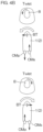
- FIG. 3 is a perspective view showing the structure of the joystick unit 18 by way of example.
- the joystick unit 18 includes the joystick 8, which can be inclined forward, backward, leftward, and rightward (i.e., in all 360-degree directions) and can be pivoted (twisted) about its axis.
- the joystick unit 18 further includes the operation buttons 180.
- the operation buttons 180 include a joystick button 181 and holding mode setting buttons 182 to 184.
- the joystick button 181 is an operator to be operated by the user to select a control mode (watercraft maneuvering mode) utilizing the joystick 8, i.e., the joystick mode.
- the holding mode setting buttons 182, 183, 184 are operation buttons to be operated by the user to select position/azimuth holding control modes (examples of an automatic watercraft maneuvering mode). More specifically, the holding mode setting button 182 is operated to select a fixed point holding mode (Stay Point TM ) in which the position and the bow azimuth (or the stern azimuth) of the watercraft 1 are maintained. The holding mode setting button 183 is operated to select a position holding mode (Fish Point TM ) in which the position of the watercraft 1 is maintained but the bow azimuth (or the stern azimuth) of the watercraft 1 is not maintained. The holding mode setting button 184 is operated to select an azimuth holding mode (Drift Point TM ) in which the bow azimuth (or the stern azimuth) of the watercraft 1 is maintained but the position of the watercraft 1 is not maintained.
- a fixed point holding mode Stay Point TM
- the holding mode setting button 183 is operated to select a position holding mode
- the control mode of the main controller 50 can be classified into an ordinary mode, the joystick mode, or the automatic watercraft maneuvering mode in terms of the operation system.
- a steering control operation is performed according to the operation angle signal generated by the steering wheel unit 16, and a propulsive force control operation is performed according to the operation signal (operation position signal) of the remote control lever 7.
- the ordinary mode is a default control mode of the main controller 50.
- the steering control operation specifically, the steering ECUs 22 of the outboard motors OM respectively drive the steering actuators 25 according to the operation angle signal generated by the steering wheel unit 16 or the steering angle commands generated by the remote control ECUs 51.
- the bodies of the outboard motors OM are steered leftward and rightward such that the propulsive force directions of the outboard motors OM are changed leftward and rightward with respect to the hull 2.
- the engine ECUs 21 of the outboard motors OM drive the shift actuators 28 and the throttle actuators 27 according to the propulsive force commands (the shift commands and the output commands) applied from the remote control ECUs 51 to the engine ECUs 21.
- the shift positions of the outboard motors OM are each set to the forward shift position, the reverse shift position or the neutral shift position, and the engine outputs (specifically, the engine rotation speeds) of the outboard motors OM are changed.
- the steering control operation and the propulsive force control operation are performed according to the operation signal of the joystick 8 of the joystick unit 18.
- the steering control operation and the propulsive force control operation are performed on the outboard motors OM. That is, the main controller 50 applies the steering angle command and the propulsive force command to the remote control ECUs 51, and the remote control ECUs 51 apply the steering angle command to the steering ECUs 22 and apply the propulsive force command to the engine ECUs 21.
- the steering control operation and/or the propulsive force control operation are automatically performed by the functions of the main controller 50 and the like without the operation of the steering wheel 6, the remote control lever 7 and the joystick 8. That is, an automatic watercraft maneuvering operation is performed.
- the automatic watercraft maneuvering operation includes an automatic watercraft maneuvering operation to be performed on a sailing basis during sailing, and an automatic watercraft maneuvering operation to be performed on a position/azimuth holding basis to maintain the position and/or the azimuth. Examples of the automatic watercraft maneuvering operation on the sailing basis include the automatic steering operations to be selected by operating the function switches 61.
- Examples of the automatic watercraft maneuvering operation on the position/azimuth holding basis include watercraft maneuvering operations to be performed in the fixed point holding mode, the position holding mode and the azimuth holding mode which are respectively selected by operating the holding mode setting buttons 182, 183, 184.
- FIGS. 4A and 4B are diagrams for describing the joystick mode in the cooperative mode, showing operation states of the joystick 8 and corresponding behaviors of the hull 2. If the joystick mode is selected by operating the joystick button 181, the main controller 50 performs a joystick mode control operation. If the cooperative mode is selected before the joystick mode is selected, or if the cooperative mode is selected after the joystick mode is selected, the main controller 50 performs the joystick mode control operation according to the cooperative mode. If the cooperative mode is not selected, the main controller 50 performs the joystick mode control operation according to the non-cooperative mode.
- the main controller 50 defines the inclination of the joystick 8 as a translation command. Specifically, the main controller 50 defines the inclination direction of the joystick 8 as an advancing direction command, and defines the inclination amount of the joystick 8 as a propulsive force magnitude command that indicates the magnitude of the propulsive force to be applied in the advancing direction. Further, the main controller 50 defines the pivoting (twisting) of the joystick 8 about its axis is defined as a bow turning command.
- the main controller 50 defines the pivoting direction of the joystick 8 about its axis (with respect to the neutral position of the joystick 8) as a bow turning direction command, and defines the pivoting amount of the joystick 8 (with respect to the neutral position of the joystick 8) as a bow turning speed command.
- the main controller 50 inputs the steering angle command and the propulsive force command to the remote control ECUs 51, and inputs the propulsive force command to the motor controller 43 of the bow thruster BT.
- the remote control ECUs 51 transmit the steering angle command to the steering ECUs 22 of the respective outboard motors OM, and transmit the propulsive force command to the engine ECUs 21 of the respective outboard motors OM.
- the outboard motors OM are respectively steered to steering angles according to the steering command, and the shift positions and the engine rotation speeds of the respective outboard motors OM are controlled to generate propulsive forces according to the propulsive force command.
- the motor controller 43 controls the rotation direction and the rotation speed of the electric motor 42 so as to generate a propulsive force having a direction and a magnitude according to the propulsive force command.
- the joystick 8 is an example of the translation/bow turning operator to be operated by the user to apply the translation command for the translation of the hull 2 and the bow turning command for the bow turning of the hull 2.
- FIG. 4A A control mode of the main controller 50 in which the translation movement is achieved according to the operation (inclination operation) of the joystick 8 as shown in FIG. 4A corresponds to the translation watercraft maneuvering mode.
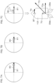
- the translation movement is typically achieved by driving one of the outboard motors OM forward and driving the other outboard motor OM in reverse with the propulsive force action lines 71s, 71p of the two outboard motors OMs, OMp crossing each other in the hull 2 as shown in FIGS. 5A and 5B .
- the propulsive force action lines 71s, 71p respectively extend through the action points of the propulsive forces 72s, 72p of the outboard motors OMs, OMp along the directions of the propulsive forces 72s, 72p.
- the two outboard motors OM are steered in an inverted V-shaped orientation as seen in plan (in a so-called toe-in orientation).
- the bow thruster BT is in a stop state, and the steering angles of the two outboard motors OM are controlled so that the propulsive force action lines 71s, 71p of the outboard motors OM cross each other at the turning center 70 (resistance center) of the hull 2.
- a resultant propulsive force 73 which is the resultant force of the propulsive forces 72s, 72p generated by the two outboard motors OMs, OMp causes the hull 2 to translate (to move laterally) without applying a moment to the hull 2.
- the resultant propulsive force 73 is directed obliquely with respect to the lateral direction of the hull 2 and, therefore, is applied to the hull 2 for oblique translation.
- the propulsive force 74 generated by the bow thruster BT also applies a moment to the hull 2 about the turning center 70. Therefore, the propulsive forces 72s, 72p, 74 of the outboard motors OM and the bow thruster BT are controlled so as to balance the moments applied to the hull 2 by the resultant propulsive force 73 of the two outboard motors OM and the propulsive force 74 of the bow thruster BT.
- the hull 2 translates (moves laterally) without the bow turning.
- the overall propulsive force contributable to the translation is greater than in the non-cooperative mode, making it possible to smoothly translate the hull 2. More specifically, the hull 2 can start moving earlier.
- the translation mode steering angles are the steering angles of the two outboard motors OM observed when the propulsive force action lines 71s, 71p of the two outboard motors OM cross each other on a line extending anteroposteriorly through the turning center 70 in the hull 2 (on the center line 2a when the turning center 70 is on the center line 2a).
- the translation mode steering angles without the bow turning of the hull 2 are the steering angles of the two outboard motors OM observed when the propulsive force action lines 71s, 71p of the two outboard motors OM cross each other at the turning center 70.
- the translation mode steering angles without the bow turning of the hull 2 are the steering angles of the two outboard motors OM observed when the propulsive force action lines 71s, 71p of the two outboard motors OM cross each other on the rear side of the turning center 70.
- the hull 2 When the joystick 8 is inclined and pivoted, the hull 2 is in a hull behavior such that the bow is turned in a direction corresponding to the pivoting direction of the joystick 8 while the hull 2 is moved in a direction corresponding to the inclination direction of the joystick 8.
- the hull 2 can be translated with the bow turning depending on the magnitude balance between the propulsive force 74 of the bow thruster BT and the resultant propulsive force 73 of the two outboard motors OM as shown in FIGS. 5C and 5D .
- the main controller 50 increases the output (propulsive force) of the bow thruster BT, and reduces the absolute values of the steering angles of the outboard motors OM (see FIG. 5C ). By thus reducing the absolute values of the steering angles of the outboard motors OM, the bow turning moment applied by the resultant propulsive force 73 is reduced.
- the bow turning command is inputted from the joystick 8 for bow turning in a direction corresponding to the advancing direction indicated by the translation command
- the main controller 50 increases the output (propulsive force) of the bow thruster BT, and reduces the absolute values of the steering angles of the outboard motors OM (see FIG. 5C ).
- the propulsive force action lines 71s, 71p are illustrated as crossing each other at the turning center 70 by way of example, but the steering angles of the outboard motors OM may be set so that the propulsive force action lines 71s, 71p cross each other on the front side of the turning center 70.
- the resultant propulsive force 73 applies the bow turning moment to the hull 2 in the same direction as that of the propulsive force 74 of the bow thruster BT.
- the main controller 50 reduces the output (propulsive force) of the bow thruster BT, and increases the absolute values of the steering angles of the outboard motors OM (see FIG. 5D ). By thus increasing the absolute values of the steering angles of the outboard motors OM, the bow turning moment applied by the resultant propulsive force 73 is increased.
- the hull 2 can be translated with the bow turning by controlling the steering angles of the two outboard motors OM so that the propulsive force action lines 71s, 71p of the two outboard motors OM cross each other on the front side or the rear side of the turning center 70.
- the resultant propulsive force 73 of the two outboard motors OM depends on the directions and the magnitudes of the propulsive forces 72s, 72p of the outboard motors OM, i.e., the steering angles and the outputs (engine rotation speeds) of the respective outboard motors OM. That is, even with the same engine outputs, the resultant propulsive force 73 is relatively reduced by reducing the absolute values of the steering angles to relatively reduce (or narrow) an angle defined between the two outboard motors OM as shown in FIG. 5C . Further, even with the same engine outputs, the resultant propulsive force 73 is relatively increased by increasing the absolute values of the steering angles to relatively increase (or expand) the angle defined between the two outboard motors OM as shown in FIG. 5D .
- the bow of the hull 2 is turned in a direction corresponding to the pivoting direction of the joystick 8 without any substantial position change. That is, the hull 2 is in a hull behavior of fixed point bow turning. Examples of the fixed point bow turning are shown in FIG. 4B .
- the steering angles of the two outboard motors OM are set to zero (bow turning mode steering angles), so that the two outboard motors OM generate propulsive forces parallel to the center line 2a. That is, the propulsive force action lines of the two outboard motors OM are parallel to the center line 2a, i.e., parallel to the anteroposterior direction of the hull 2.
- one of the outboard motors OM is driven forward, and the other outboard motor OM is driven in reverse such that a moment can be applied to the hull 2 about the turning center.
- the starboard-side outboard motor OMs For the fixed point bow turning in a leftward direction (in a counterclockwise direction as seen in plan), the starboard-side outboard motor OMs is driven forward, and the port-side outboard motor OMp is driven in reverse.
- the starboard-side outboard motor OMs For the fixed point bow turning in a rightward direction (in a clockwise direction as seen in plan), the starboard-side outboard motor OMs is driven in reverse, and the port-side outboard motor OMp is driven forward.
- the bow thruster BT In the non-cooperative mode, the bow thruster BT is in the stop state. In the cooperative mode, the bow thruster BT also generates a propulsive force to promote the bow turning. That is, the bow thruster BT applies a leftward propulsive force to the hull 2 for the fixed point bow turning in the leftward direction (in the counterclockwise direction as seen in plan). For the fixed point bow turning in the rightward direction (in the clockwise direction as seen in plan), the bow thruster BT applies a rightward propulsive force to the hull 2.
- the calibration is performed to find a calibration value which is a control parameter so that the lateral translation of the hull 2, i.e., the lateral movement without the bow turning (hereinafter referred to simply as "lateral movement”), can be properly achieved.
- the translation movement can be achieved according to the operation of the joystick 8 as intended by the user.
- the calibration includes calibration for lateral movement in a rightward direction (hereinafter referred to as “rightward lateral movement”) and calibration for lateral movement in a leftward direction (hereinafter referred to as "leftward lateral movement”).
- a calibration value for the rightward lateral movement and a calibration value for the leftward lateral movement are generated, and stored in the memory 50b (see FIG. 2 ).
- a procedure and a process in which calibration of the rightward lateral movement is first performed and then calibration of the leftward lateral movement is performed will hereinafter be described.
- a procedure and a process in which calibration of the leftward lateral movement is first performed and then calibration of the rightward lateral movement is performed can be provided by exchanging between "rightward" and "leftward” in the following description.
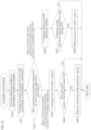
- FIG. 6 is a flowchart showing the process to be performed by the main controller 50 for calibration of the lateral movement.
- the user can start the calibration by performing a predetermined calibration start operation to apply a calibration mode command to the main controller 50.
- the calibration start operation may be, for example, the long-pressing of the joystick button 181. If the calibration start operation is performed (YES in Step S1), the control mode of the main controller 50 is switched to the calibration mode (Step S2). The user may be notified of the calibration mode by an indicator such as an LED lamp (not shown) provided in the joystick unit 18.
- the main controller 50 Upon the switching to the calibration mode, the main controller 50 reads out a calibration value from the memory 50b and, when the user operates the joystick 8, the main controller 50 generates a propulsive force command and a steering angle command by using the calibration value (Step S3). If the calibration value is used for the first time for the calibration, the calibration value is a default value preliminarily written in the memory 50b. Where the calibration has been previously performed, the calibration value is a value set for the previous calibration. However, the calibration value set for the previous calibration can be reset to the default value by a reset operation to be described below.
- the user performs a lateral movement operation for lateral movement in one of opposite lateral directions for the calibration.
- the user performs a rightward lateral movement operation, i.e., inclines the joystick 8 rightward by way of example.
- the user observes the behavior of the hull 2. If the hull 2 is moved right-forward, the user changes the inclination direction of the joystick 8 to a right rearward direction in order to correct the hull movement. If the hull 2 is moved right-rearward, the user changes the inclination direction of the joystick 8 to a right forward direction in order to correct the hull movement. If the bow of the hull 2 is turned clockwise, the user twists the joystick 8 counterclockwise in order to correct the bow turning. If the bow of the hull 2 is turned counterclockwise, the user twists the joystick 8 clockwise in order to correct the bow turning.
- the operation signal of the joystick 8 is inputted from the joystick unit 18 to the main controller 50.
- the main controller 50 changes the propulsive force command for the bow thruster BT and the propulsive force command and the steering angle command for the outboard motors OM (Step S4). If the operation state of the joystick 8 is such that the hull 2 can thus achieve the rightward lateral movement behavior, the user performs a decision operation (YES in Step S5).
- the joystick button 181 may be pressed for the decision operation.
- the joystick button 181 is an example of the calibration ending operator.
- the main controller 50 determines whether or not the joystick 8 is in the neutral position (Step S6). If the joystick 8 is not in the neutral position, a calibration value for the rightward lateral movement is written and set in the memory 50b (Step S7). The calibration value written in the memory 50b is used when the main controller 50 thereafter computes the propulsive force command and the steering angle command according to the operation of the joystick 8 for the watercraft maneuvering with the use of the joystick 8.
- the calibration value for the rightward lateral movement is used for the computation of the propulsive force command and the steering angle command when an inclination operation including a rightward inclination component is performed on the joystick 8 (i.e., the translation command includes a rightward movement component) in the joystick mode.
- the main controller 50 computes the calibration value based on the control states of the bow thruster BT and the two outboard motors OM observed when the decision operation is performed (Step S5), and writes the calibration value in the memory 50b. Specific examples of the calibration value will be described below.
- the control mode is thereafter switched to the joystick mode (Step S8).
- the resultant propulsive force 73 (see FIGS. 5A and 5B ) generated by the outboard motors OM is increased. Further, as the joystick level increases, the propulsive force 74 (see FIG. 5B ) generated by the bow thruster BT is increased. The increment in the resultant propulsive force 73 due to the setting of the translation steering angles varies according to the propulsive forces generated by the outboard motors OM.
- the two outboard motors OM are provided on the stern 3.
- the number of the outboard motors OM may be three or more.
- the engine outboard motors are used as the propulsion devices by way of example, but instead electric outboard motors may be used.
- the propulsion devices are not necessarily required to be the outboard motors, but may be inboard motors, inboard/outboard motors (stern drives), waterjet propulsion devices and other types of propulsion devices.
- the bow thruster BT is able to generate the propulsive force only laterally leftward and rightward by way of example.
- a steerable propulsion device such as an electric trolling motor may be provided at the bow instead of the propulsion device able to generate the propulsive force only laterally leftward and rightward.
- the bow thruster may be a propulsion device provided at the bow and able to generate the propulsive force laterally leftward and rightward and further generate the propulsive force in directions other than the leftward and rightward directions.
- the watercraft propulsion system 100 includes the cooperative mode in which the outboard motors OM and the bow thruster BT are controlled in a cooperative manner, and the non-cooperative mode in which the cooperative control is not performed by way of example.
- the non-cooperative mode may be omitted.
Landscapes
- Engineering & Computer Science (AREA)
- Chemical & Material Sciences (AREA)
- Combustion & Propulsion (AREA)
- Mechanical Engineering (AREA)
- Ocean & Marine Engineering (AREA)
- Aviation & Aerospace Engineering (AREA)
- Radar, Positioning & Navigation (AREA)
- Remote Sensing (AREA)
- Physics & Mathematics (AREA)
- General Physics & Mathematics (AREA)
- Automation & Control Theory (AREA)
- Control Of Position, Course, Altitude, Or Attitude Of Moving Bodies (AREA)
Claims (8)
- Antriebssystem (100) für ein Wasserfahrzeug, umfassend:ein Bugstrahlruder (BT) an einem Bug eines Rumpfes (2) zum Erzeugen einer seitlichen Antriebskraft,mindestens zwei Antriebsvorrichtungen (OM) an einem Heck (3) des Rumpfes (2), die jeweils einen variablen Lenkwinkel aufweisen,ein Bedienelement für die Translation/Bugdrehung (8), welches von einem Benutzer betätigt wird, um einen Translationsbefehl zum Verschieben des Rumpfes (2) und einen Bugdrehbefehl zum Drehen des Buges des Rumpfes (2) zu erteilen, und eine Steuereinheit (50), die so konfiguriert oder programmiert ist, dass sie das Bugstrahlruder (BT) und die mindestens zwei Antriebsvorrichtungen (OM) steuert, wobeidie Steuereinheit (50) so konfiguriert oder programmiert ist, dass sie in einem Modus zum Manövrieren durch Translation des Wasserfahrzeugs das Bugstrahlruder (BT) antreibt und eine der mindestens zwei Antriebsvorrichtungen (OM) vorwärts antreibt und eine andere der mindestens zwei Antriebsvorrichtungen (OM) rückwärts antreibt, während sie die Lenkwinkel der mindestens zwei Antriebsvorrichtungen (OM) so steuert, dass die Antriebskraftwirkungslinien (71s, 71p) der mindestens zwei Antriebsvorrichtungen (OM) sich im Rumpf (2) kreuzen, um den Rumpf (2) in Reaktion auf eine Betätigung des Bedienelements für die Translation/Bugdrehung (8) zu verschieben, unddadurch gekennzeichnet, dassdie Steuereinheit (50) einen Kalibrierungsmodus umfasst, in dem eine Kalibrierung für den Modus zum Manövrieren durch Translation des Wasserfahrzeugs durchgeführt wird,die Steuereinheit (50) so konfiguriert oder programmiert ist, dass sie das Bugstrahlruder (BT) und die mindestens zwei Antriebsvorrichtungen (OM) gemäß dem Translationsbefehl und dem Bugdrehbefehl, die vom Bedienelement für die Translation/Bugdrehung (8) im Kalibrierungsmodus gegeben werden, steuert,die Steuereinheit (50) so konfiguriert oder programmiert ist, dass sie eine Leistung des Bugstrahlruders (BT) steigert, wenn der Bugdrehbefehl ein Befehl, der die Bugdrehung fördert, ist, welcher eine Bugdrehung in einer durch den Translationsbefehl angegebenen Richtung befiehlt, und dass sie die Absolutwerte der Lenkwinkel der mindestens zwei Antriebsvorrichtungen (OM) verringert, wenn der Befehl, der die Bugdrehung fördert, auch dann noch gegeben ist, nachdem die Leistung des Bugstrahlruders (BT) einen oberen Grenzwert erreicht, unddie Steuereinrichtung (50) so konfiguriert oder programmiert ist, dass sie die Absolutwerte der Lenkwinkel der mindestens zwei Antriebsvorrichtungen (OM) erhöht, wenn der Bugdrehbefehl ein Befehl zur Verringerung der Bugdrehung ist, welcher eine Bugdrehung in einer Richtung entgegengesetzt zu der durch den Translationsbefehl angegebenen Richtung befiehlt, und dass sie die Leistung des Bugstrahlruders (BT) verringert, wenn der Befehl zur Verringerung der Bugdrehung auch dann noch angewendet wird, nachdem die Absolutwerte der Lenkwinkel eine Obergrenze erreichen.
- Antriebssystem (100) für ein Wasserfahrzeug gemäß Anspruch 1, ferner umfassend:ein Bedienelement zum Beenden der Kalibrierung (181), das vom Benutzer betätigt wird, um die Kalibrierung zu beenden, wobeidie Steuereinheit (50) so konfiguriert oder programmiert ist, dass sie einen Kalibrierungswert auf der Grundlage der Steuerzustände des Bugstrahlruders (BT) und der mindestens zwei Antriebsvorrichtungen (OM) erzeugt, wenn das Bedienelement zum Beenden der Kalibrierung (181) betätigt wird, und den Kalibrierungswert in einem Speicher (50b) speichert.
- Antriebssystem (100) für ein Wasserfahrzeug gemäß Anspruch 2, wobei der Kalibrierungswert umfasst: Translationslenkwinkel, auf welche die Lenkwinkel der mindestens zwei Antriebsvorrichtungen (OM) im Modus zum Manövrieren durch Translation des Wasserfahrzeugs eingestellt werden sollen, ein Referenzverhältnis, das ein Verhältnis der Leistung des Bugstrahlruders (BT) zu einer seitlichen Komponente eines Zielschubs angibt, welcher dem vom Bedienelement für die Translation/Bugdrehung (8) erteilten Translationsbefehl entspricht, und ein Verhältnis von Vorwärts-/Rückwärtsschub, das ein Verhältnis zwischen einer Antriebskraft einer der mindestens zwei Antriebsvorrichtungen (OM), welche vorwärts angetrieben wird, und einer Antriebskraft der anderen der mindestens zwei Antriebsvorrichtungen (OM), welche rückwärts angetrieben wird, angibt.
- Antriebssystem (100) für ein Wasserfahrzeug gemäß Anspruch 2 oder 3, wobei die Steuereinheit (50) so konfiguriert oder programmiert ist, dass sie die Leistung des Bugstrahlruders (BT), die Lenkwinkel der mindestens zwei Antriebsvorrichtungen (OM) und die Antriebskräfte der mindestens zwei Antriebsvorrichtungen (OM) auf der Grundlage des Kalibrierungswerts steuert, wenn der Translationsbefehl vom Bedienelement für die Translation/Bugdrehung (8) im Modus zum Manövrieren durch Translation des Wasserfahrzeugs gegeben wird.
- Antriebssystem (100) für ein Wasserfahrzeug gemäß einem der Ansprüche 1 bis 4, wobei die Steuereinheit (50) so konfiguriert oder programmiert ist, dass sie die Leistung des Bugstrahlruders (BT) steigert und die Absolutwerte der Lenkwinkel der Antriebsvorrichtungen (OM) verringert, wenn ein Bugdrehbefehl, der die Bugdrehung in der durch den Translationsbefehl angegebenen Richtung befiehlt, vom Bedienelement für die Translation/Bugdrehung (8) im Modus zum Manövrieren durch Translation des Wasserfahrzeugs gegeben wird.
- Antriebssystem (100) für ein Wasserfahrzeug gemäß einem der Ansprüche 1 bis 5, wobei die Steuereinheit (50) so konfiguriert oder programmiert ist, dass sie die Leistung des Bugstrahlruders (BT) verringert und die Absolutwerte der Lenkwinkel der Antriebsvorrichtungen (OM) steigert, wenn ein Bugdrehbefehl, der eine Bugdrehung in einer Richtung entgegengesetzt zu der durch den Translationsbefehl angegebenen Richtung bewirkt, vom Bedienelement für die Translation/Bugdrehung (8) im Modus zum Manövrieren durch Translation des Wasserfahrzeugs gegeben wird.
- Antriebssystem (100) für ein Wasserfahrzeug gemäß einem der Ansprüche 1 bis 6, welches ferner einen oberen Leistungsbegrenzer (10), der vom Benutzer betätigt wird, um eine Obergrenze für die Leistung des Bugstrahlruders (BT) festzulegen, umfasst.
- Wasserfahrzeug (1), umfassend:einen Rumpf (2) unddas Antriebssystem (100) für ein Wasserfahrzeug gemäß einem der Ansprüche 1 bis 7 an dem Rumpf (2).
Applications Claiming Priority (1)
| Application Number | Priority Date | Filing Date | Title |
|---|---|---|---|
| JP2022178985A JP2024068486A (ja) | 2022-11-08 | 2022-11-08 | 船舶推進システムおよびそれを備える船舶 |
Publications (2)
| Publication Number | Publication Date |
|---|---|
| EP4368492A1 EP4368492A1 (de) | 2024-05-15 |
| EP4368492B1 true EP4368492B1 (de) | 2025-07-02 |
Family
ID=88745939
Family Applications (1)
| Application Number | Title | Priority Date | Filing Date |
|---|---|---|---|
| EP23208424.4A Active EP4368492B1 (de) | 2022-11-08 | 2023-11-08 | Wasserfahrzeugantriebssystem und wasserfahrzeug mit dem wasserfahrzeugantriebssystem |
Country Status (3)
| Country | Link |
|---|---|
| US (1) | US20240152146A1 (de) |
| EP (1) | EP4368492B1 (de) |
| JP (1) | JP2024068486A (de) |
Families Citing this family (2)
| Publication number | Priority date | Publication date | Assignee | Title |
|---|---|---|---|---|
| US20250321594A1 (en) * | 2024-04-16 | 2025-10-16 | Navico Group Americas, LLC | Systems and methods for controlling a watercraft via propulsion devices |
| US20260077851A1 (en) | 2024-09-18 | 2026-03-19 | Ultraflex S.P.A. | Method and system of governing a boat or the like |
Family Cites Families (11)
| Publication number | Priority date | Publication date | Assignee | Title |
|---|---|---|---|---|
| ITRM20040498A1 (it) * | 2004-10-13 | 2005-01-13 | Stefano Bertazzoni | Sistema di controllo automatico della manovra di imbarcazioni a motore, relativo metodo, ed imbarcazione provvista del sistema. |
| EP1981757B1 (de) * | 2006-02-01 | 2017-06-21 | CPAC Systems AB | Verfahren und anordnung zur steuerung einer antriebsanordnung in einem wasserfahrzeug |
| JP5151168B2 (ja) * | 2007-01-31 | 2013-02-27 | 株式会社Ihi | バウスラスタと旋回式スラスタを有する2軸船の推力制御方法及び装置 |
| JP5764411B2 (ja) * | 2011-06-30 | 2015-08-19 | ヤンマー株式会社 | 船舶操船装置 |
| JP5982716B2 (ja) * | 2012-08-08 | 2016-08-31 | ヤマハ発動機株式会社 | 船舶推進制御装置、船舶推進装置および船舶 |
| JP6250520B2 (ja) * | 2014-10-23 | 2017-12-20 | ヤンマー株式会社 | 操船装置 |
| JP6430985B2 (ja) * | 2016-03-25 | 2018-11-28 | ヤンマー株式会社 | 操船装置及びそれを備えた船舶 |
| JP6430988B2 (ja) * | 2016-03-31 | 2018-11-28 | ヤンマー株式会社 | 操船装置 |
| WO2020069750A1 (en) * | 2018-10-05 | 2020-04-09 | Cpac Systems Ab | Thruster assisted docking |
| US11372412B1 (en) * | 2019-03-25 | 2022-06-28 | Yamaha Hatsudoki Kabushiki Kaisha | Vessel steering system and vessel steering method |
| JP2020168921A (ja) * | 2019-04-02 | 2020-10-15 | ヤマハ発動機株式会社 | 船舶用推進システムおよび船舶 |
-
2022
- 2022-11-08 JP JP2022178985A patent/JP2024068486A/ja active Pending
-
2023
- 2023-11-07 US US18/503,472 patent/US20240152146A1/en active Pending
- 2023-11-08 EP EP23208424.4A patent/EP4368492B1/de active Active
Also Published As
| Publication number | Publication date |
|---|---|
| US20240152146A1 (en) | 2024-05-09 |
| EP4368492A1 (de) | 2024-05-15 |
| JP2024068486A (ja) | 2024-05-20 |
Similar Documents
| Publication | Publication Date | Title |
|---|---|---|
| EP3805088A1 (de) | Verfahren zur steuerung von lagekontrollklappen eines seeschiffs, steuerungssystem zur steuerung von lagekontrollklappen, die an einem seeschiff montiert werden, und seeschiff | |
| EP4368492B1 (de) | Wasserfahrzeugantriebssystem und wasserfahrzeug mit dem wasserfahrzeugantriebssystem | |
| EP2907742A1 (de) | System zur steuerung eines schiffs, verfahren zur steuerung eines schiffs und programm | |
| EP4357237B1 (de) | Wasserfahrzeugantriebssystem, wasserfahrzeug und wasserfahrzeugantriebssteuerungsverfahren | |
| EP4365074B1 (de) | Wasserfahrzeugantriebssystem, wasserfahrzeug und wasserfahrzeugantriebssteuerungsverfahren | |
| JP2022129788A (ja) | 船を制御するためのシステム及び方法 | |
| EP4375182B1 (de) | Wasserfahrzeugantriebssystem und wasserfahrzeug mit dem wasserfahrzeugantriebssystem | |
| EP4368493A1 (de) | Wasserfahrzeugantriebssystem und wasserfahrzeug mit dem wasserfahrzeugantriebssystem | |
| EP4378815A1 (de) | Wasserfahrzeugantriebssystem und wasserfahrzeug mit dem wasserfahrzeugantriebssystem | |
| US20250050992A1 (en) | Watercraft propulsion system, and watercraft | |
| EP4524028A1 (de) | Wasserfahrzeugantriebssystem und wasserfahrzeug | |
| US20250050998A1 (en) | Watercraft propulsion system and watercraft | |
| US20250050994A1 (en) | Watercraft propulsion system and watercraft | |
| EP4516658A1 (de) | Schiffsantriebssystem, steuerungsverfahren dafür und wasserfahrzeug | |
| US12612148B2 (en) | Marine propulsion system, control method therefor, and marine vessel | |
| US20250388296A1 (en) | Marine vessel and control device therefor | |
| EP4520648A1 (de) | Schiffsantriebssystem, steuerungsverfahren dafür und wasserfahrzeug | |
| US20240239464A1 (en) | Watercraft maneuvering system and watercraft including the watercraft maneuvering system |
Legal Events
| Date | Code | Title | Description |
|---|---|---|---|
| PUAI | Public reference made under article 153(3) epc to a published international application that has entered the european phase |
Free format text: ORIGINAL CODE: 0009012 |
|
| STAA | Information on the status of an ep patent application or granted ep patent |
Free format text: STATUS: THE APPLICATION HAS BEEN PUBLISHED |
|
| AK | Designated contracting states |
Kind code of ref document: A1 Designated state(s): AL AT BE BG CH CY CZ DE DK EE ES FI FR GB GR HR HU IE IS IT LI LT LU LV MC ME MK MT NL NO PL PT RO RS SE SI SK SM TR |
|
| P01 | Opt-out of the competence of the unified patent court (upc) registered |
Free format text: CASE NUMBER: APP_37571/2024 Effective date: 20240624 |
|
| STAA | Information on the status of an ep patent application or granted ep patent |
Free format text: STATUS: REQUEST FOR EXAMINATION WAS MADE |
|
| 17P | Request for examination filed |
Effective date: 20241002 |
|
| RBV | Designated contracting states (corrected) |
Designated state(s): AL AT BE BG CH CY CZ DE DK EE ES FI FR GB GR HR HU IE IS IT LI LT LU LV MC ME MK MT NL NO PL PT RO RS SE SI SK SM TR |
|
| GRAP | Despatch of communication of intention to grant a patent |
Free format text: ORIGINAL CODE: EPIDOSNIGR1 |
|
| STAA | Information on the status of an ep patent application or granted ep patent |
Free format text: STATUS: GRANT OF PATENT IS INTENDED |
|
| INTG | Intention to grant announced |
Effective date: 20250212 |
|
| GRAS | Grant fee paid |
Free format text: ORIGINAL CODE: EPIDOSNIGR3 |
|
| GRAA | (expected) grant |
Free format text: ORIGINAL CODE: 0009210 |
|
| STAA | Information on the status of an ep patent application or granted ep patent |
Free format text: STATUS: THE PATENT HAS BEEN GRANTED |
|
| AK | Designated contracting states |
Kind code of ref document: B1 Designated state(s): AL AT BE BG CH CY CZ DE DK EE ES FI FR GB GR HR HU IE IS IT LI LT LU LV MC ME MK MT NL NO PL PT RO RS SE SI SK SM TR |
|
| REG | Reference to a national code |
Ref country code: GB Ref legal event code: FG4D |
|
| REG | Reference to a national code |
Ref country code: CH Ref legal event code: EP |
|
| REG | Reference to a national code |
Ref country code: DE Ref legal event code: R096 Ref document number: 602023004510 Country of ref document: DE |
|
| REG | Reference to a national code |
Ref country code: IE Ref legal event code: FG4D |
|
| REG | Reference to a national code |
Ref country code: NL Ref legal event code: MP Effective date: 20250702 |
|
| PG25 | Lapsed in a contracting state [announced via postgrant information from national office to epo] |
Ref country code: PT Free format text: LAPSE BECAUSE OF FAILURE TO SUBMIT A TRANSLATION OF THE DESCRIPTION OR TO PAY THE FEE WITHIN THE PRESCRIBED TIME-LIMIT Effective date: 20251103 |
|
| PG25 | Lapsed in a contracting state [announced via postgrant information from national office to epo] |
Ref country code: NL Free format text: LAPSE BECAUSE OF FAILURE TO SUBMIT A TRANSLATION OF THE DESCRIPTION OR TO PAY THE FEE WITHIN THE PRESCRIBED TIME-LIMIT Effective date: 20250702 |
|
| REG | Reference to a national code |
Ref country code: AT Ref legal event code: MK05 Ref document number: 1808966 Country of ref document: AT Kind code of ref document: T Effective date: 20250702 |
|
| PG25 | Lapsed in a contracting state [announced via postgrant information from national office to epo] |
Ref country code: IS Free format text: LAPSE BECAUSE OF FAILURE TO SUBMIT A TRANSLATION OF THE DESCRIPTION OR TO PAY THE FEE WITHIN THE PRESCRIBED TIME-LIMIT Effective date: 20251102 |
|
| PGFP | Annual fee paid to national office [announced via postgrant information from national office to epo] |
Ref country code: DE Payment date: 20251119 Year of fee payment: 3 |
|
| PG25 | Lapsed in a contracting state [announced via postgrant information from national office to epo] |
Ref country code: NO Free format text: LAPSE BECAUSE OF FAILURE TO SUBMIT A TRANSLATION OF THE DESCRIPTION OR TO PAY THE FEE WITHIN THE PRESCRIBED TIME-LIMIT Effective date: 20251002 |
|
| REG | Reference to a national code |
Ref country code: LT Ref legal event code: MG9D |
|
| PG25 | Lapsed in a contracting state [announced via postgrant information from national office to epo] |
Ref country code: AT Free format text: LAPSE BECAUSE OF FAILURE TO SUBMIT A TRANSLATION OF THE DESCRIPTION OR TO PAY THE FEE WITHIN THE PRESCRIBED TIME-LIMIT Effective date: 20250702 |
|
| PG25 | Lapsed in a contracting state [announced via postgrant information from national office to epo] |
Ref country code: FI Free format text: LAPSE BECAUSE OF FAILURE TO SUBMIT A TRANSLATION OF THE DESCRIPTION OR TO PAY THE FEE WITHIN THE PRESCRIBED TIME-LIMIT Effective date: 20250702 |
|
| PGFP | Annual fee paid to national office [announced via postgrant information from national office to epo] |
Ref country code: IT Payment date: 20251201 Year of fee payment: 3 |
|
| PG25 | Lapsed in a contracting state [announced via postgrant information from national office to epo] |
Ref country code: HR Free format text: LAPSE BECAUSE OF FAILURE TO SUBMIT A TRANSLATION OF THE DESCRIPTION OR TO PAY THE FEE WITHIN THE PRESCRIBED TIME-LIMIT Effective date: 20250702 |
|
| PGFP | Annual fee paid to national office [announced via postgrant information from national office to epo] |
Ref country code: FR Payment date: 20251126 Year of fee payment: 3 |
|
| PG25 | Lapsed in a contracting state [announced via postgrant information from national office to epo] |
Ref country code: GR Free format text: LAPSE BECAUSE OF FAILURE TO SUBMIT A TRANSLATION OF THE DESCRIPTION OR TO PAY THE FEE WITHIN THE PRESCRIBED TIME-LIMIT Effective date: 20251003 |
|
| PG25 | Lapsed in a contracting state [announced via postgrant information from national office to epo] |
Ref country code: CZ Free format text: LAPSE BECAUSE OF FAILURE TO SUBMIT A TRANSLATION OF THE DESCRIPTION OR TO PAY THE FEE WITHIN THE PRESCRIBED TIME-LIMIT Effective date: 20250702 Ref country code: SE Free format text: LAPSE BECAUSE OF FAILURE TO SUBMIT A TRANSLATION OF THE DESCRIPTION OR TO PAY THE FEE WITHIN THE PRESCRIBED TIME-LIMIT Effective date: 20250702 |
|
| PG25 | Lapsed in a contracting state [announced via postgrant information from national office to epo] |
Ref country code: LV Free format text: LAPSE BECAUSE OF FAILURE TO SUBMIT A TRANSLATION OF THE DESCRIPTION OR TO PAY THE FEE WITHIN THE PRESCRIBED TIME-LIMIT Effective date: 20250702 |
|
| PG25 | Lapsed in a contracting state [announced via postgrant information from national office to epo] |
Ref country code: BG Free format text: LAPSE BECAUSE OF FAILURE TO SUBMIT A TRANSLATION OF THE DESCRIPTION OR TO PAY THE FEE WITHIN THE PRESCRIBED TIME-LIMIT Effective date: 20250702 Ref country code: PL Free format text: LAPSE BECAUSE OF FAILURE TO SUBMIT A TRANSLATION OF THE DESCRIPTION OR TO PAY THE FEE WITHIN THE PRESCRIBED TIME-LIMIT Effective date: 20250702 |
|
| PG25 | Lapsed in a contracting state [announced via postgrant information from national office to epo] |
Ref country code: RS Free format text: LAPSE BECAUSE OF FAILURE TO SUBMIT A TRANSLATION OF THE DESCRIPTION OR TO PAY THE FEE WITHIN THE PRESCRIBED TIME-LIMIT Effective date: 20251002 |
|
| PG25 | Lapsed in a contracting state [announced via postgrant information from national office to epo] |
Ref country code: ES Free format text: LAPSE BECAUSE OF FAILURE TO SUBMIT A TRANSLATION OF THE DESCRIPTION OR TO PAY THE FEE WITHIN THE PRESCRIBED TIME-LIMIT Effective date: 20250702 |
|
| PG25 | Lapsed in a contracting state [announced via postgrant information from national office to epo] |
Ref country code: RO Free format text: LAPSE BECAUSE OF FAILURE TO SUBMIT A TRANSLATION OF THE DESCRIPTION OR TO PAY THE FEE WITHIN THE PRESCRIBED TIME-LIMIT Effective date: 20250702 |
|
| PG25 | Lapsed in a contracting state [announced via postgrant information from national office to epo] |
Ref country code: SM Free format text: LAPSE BECAUSE OF FAILURE TO SUBMIT A TRANSLATION OF THE DESCRIPTION OR TO PAY THE FEE WITHIN THE PRESCRIBED TIME-LIMIT Effective date: 20250702 |
|
| PG25 | Lapsed in a contracting state [announced via postgrant information from national office to epo] |
Ref country code: DK Free format text: LAPSE BECAUSE OF FAILURE TO SUBMIT A TRANSLATION OF THE DESCRIPTION OR TO PAY THE FEE WITHIN THE PRESCRIBED TIME-LIMIT Effective date: 20250702 |