EP4368829A1 - Modularer plug and play behälter - insbesondere für eine wasserstoffproduktionsanlage in verbindung mit einer windturbine - Google Patents
Modularer plug and play behälter - insbesondere für eine wasserstoffproduktionsanlage in verbindung mit einer windturbine Download PDFInfo
- Publication number
- EP4368829A1 EP4368829A1 EP22207119.3A EP22207119A EP4368829A1 EP 4368829 A1 EP4368829 A1 EP 4368829A1 EP 22207119 A EP22207119 A EP 22207119A EP 4368829 A1 EP4368829 A1 EP 4368829A1
- Authority
- EP
- European Patent Office
- Prior art keywords
- ports
- container
- compartment
- linkage
- wind turbine
- Prior art date
- Legal status (The legal status is an assumption and is not a legal conclusion. Google has not performed a legal analysis and makes no representation as to the accuracy of the status listed.)
- Withdrawn
Links
- UFHFLCQGNIYNRP-UHFFFAOYSA-N Hydrogen Chemical compound [H][H] UFHFLCQGNIYNRP-UHFFFAOYSA-N 0.000 title claims description 9
- 239000001257 hydrogen Substances 0.000 title claims description 9
- 229910052739 hydrogen Inorganic materials 0.000 title claims description 9
- 238000004519 manufacturing process Methods 0.000 title claims description 8
- 239000012530 fluid Substances 0.000 claims abstract description 9
- 238000004891 communication Methods 0.000 claims abstract description 6
- 239000007788 liquid Substances 0.000 claims abstract description 6
- 230000014759 maintenance of location Effects 0.000 claims abstract description 5
- 238000003860 storage Methods 0.000 claims abstract description 5
- 238000000034 method Methods 0.000 claims description 11
- 239000007789 gas Substances 0.000 claims description 8
- 238000007789 sealing Methods 0.000 claims description 8
- 230000007613 environmental effect Effects 0.000 description 6
- 150000003839 salts Chemical class 0.000 description 3
- XLYOFNOQVPJJNP-UHFFFAOYSA-N water Substances O XLYOFNOQVPJJNP-UHFFFAOYSA-N 0.000 description 3
- 239000004020 conductor Substances 0.000 description 2
- 230000001419 dependent effect Effects 0.000 description 1
- 230000005611 electricity Effects 0.000 description 1
- 238000000605 extraction Methods 0.000 description 1
- 238000010438 heat treatment Methods 0.000 description 1
- 239000002245 particle Substances 0.000 description 1
Images


Classifications
-
- F—MECHANICAL ENGINEERING; LIGHTING; HEATING; WEAPONS; BLASTING
- F03—MACHINES OR ENGINES FOR LIQUIDS; WIND, SPRING, OR WEIGHT MOTORS; PRODUCING MECHANICAL POWER OR A REACTIVE PROPULSIVE THRUST, NOT OTHERWISE PROVIDED FOR
- F03D—WIND MOTORS
- F03D9/00—Adaptations of wind motors for special use; Combinations of wind motors with apparatus driven thereby; Wind motors specially adapted for installation in particular locations
- F03D9/20—Wind motors characterised by the driven apparatus
- F03D9/25—Wind motors characterised by the driven apparatus the apparatus being an electrical generator
-
- F—MECHANICAL ENGINEERING; LIGHTING; HEATING; WEAPONS; BLASTING
- F03—MACHINES OR ENGINES FOR LIQUIDS; WIND, SPRING, OR WEIGHT MOTORS; PRODUCING MECHANICAL POWER OR A REACTIVE PROPULSIVE THRUST, NOT OTHERWISE PROVIDED FOR
- F03D—WIND MOTORS
- F03D9/00—Adaptations of wind motors for special use; Combinations of wind motors with apparatus driven thereby; Wind motors specially adapted for installation in particular locations
- F03D9/10—Combinations of wind motors with apparatus storing energy
- F03D9/19—Combinations of wind motors with apparatus storing energy storing chemical energy, e.g. using electrolysis
-
- F—MECHANICAL ENGINEERING; LIGHTING; HEATING; WEAPONS; BLASTING
- F05—INDEXING SCHEMES RELATING TO ENGINES OR PUMPS IN VARIOUS SUBCLASSES OF CLASSES F01-F04
- F05B—INDEXING SCHEME RELATING TO WIND, SPRING, WEIGHT, INERTIA OR LIKE MOTORS, TO MACHINES OR ENGINES FOR LIQUIDS COVERED BY SUBCLASSES F03B, F03D AND F03G
- F05B2220/00—Application
- F05B2220/61—Application for hydrogen and/or oxygen production
-
- F—MECHANICAL ENGINEERING; LIGHTING; HEATING; WEAPONS; BLASTING
- F05—INDEXING SCHEMES RELATING TO ENGINES OR PUMPS IN VARIOUS SUBCLASSES OF CLASSES F01-F04
- F05B—INDEXING SCHEME RELATING TO WIND, SPRING, WEIGHT, INERTIA OR LIKE MOTORS, TO MACHINES OR ENGINES FOR LIQUIDS COVERED BY SUBCLASSES F03B, F03D AND F03G
- F05B2240/00—Components
- F05B2240/10—Stators
- F05B2240/14—Casings, housings, nacelles, gondels or the like, protecting or supporting assemblies there within
- F05B2240/142—Casings, housings, nacelles, gondels or the like, protecting or supporting assemblies there within in the form of a standard ISO container
Definitions
- the present invention relates to connecting of a process container, the process container comprising input and/or output connections to be connected to site connections.
- the system is especially suitable for containers to be positioned in harsh conditions, such as at ocean and shore sites, where it would be exposed to weather and salt.
- the containers could comprise hydrogen production plants with electrical and fluid connections, where they are adapted to be positioned in relation to a wind turbine.
- the production plants for generating hydrogen are positioned at a platform in connection with or close to the wind turbine.
- the production plant is connected to means for the exchange of fluids and gasses, and for the supply of electrical power from the wind turbine.
- the scope of the present invention is to overcome these problems.
- a linkage of first ports is provided of a container to second ports, where the container comprises the operational parts to be powered by a wind turbine, and where the first ports are connected to conduits for electrical and/or fluid communication to transport current, gas and/or liquids between operational parts and storages outside the container, wherein, when linked, the first and second ports are positioned in a sealed compartment.
- the second ports may be positioned at a plug interface adapted to fit into an opening of the container, where the plug interface reaches into the opening when the first and second ports are linked.
- the plug interface may be formed with a sealing adapted to seal towards an inner surface of the opening, thereby sealing the opening and hence the compartment inner from the outside environments.
- the plug interface could form a raised platform.
- the first ports and/or the second ports may be formed at sections that, when linked, reaches a distance into the compartment inner.
- the ports may be formed in flanged ends of the sections or may at least be formed in substantially plane contact surfaces at the ends of the sections.
- a cover may form part of the sealing enclosure of the compartment, where the cover is removable or comprises openable ports allowing access from the outside to the ports.
- the compartment may part the container and positioned between the container side walls.
- the operational parts may include a hydrogen production plant.
- the present invention further relates to the container comprising the linkage compartment according to any of the embodiments.
- the present invention further relates to a method to link a container in connection to a wind turbine, the container comprising operational parts to be powered by the wind turbine, where linkage means are positioned within a compartment, and the linkage means of the container comprises first ports adapted to be linked to second ports, where the first ports are connected to conduits for electrical and/or fluid communication to transport current, gas and/or liquids between operational parts and storages outside the container, wherein the method includes to open or remove a cover of the compartment, link the first ports to the second ports, and replace or close the cover to seal the compartment.
- the method could be using the linkage according to any of the embodiments.
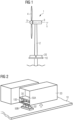
- Figure 1 shows an embodiment wind turbine 1 positioned in the water, such as the ocean.
- the wind turbine 1 comprises a tower 2 mounted on a non-depicted fundament.
- a nacelle 3 is arranged on top of the tower 2.
- the wind turbine 1 further comprises a wind rotor 5 having two, three or more blades 4 (in the perspective of Figure 1 only two blades 4 are visible).
- the wind rotor 5 is rotatable around a longitudinal rotation axis Y.
- the wind turbine 1 comprises an electric generator.
- a platform 10 is positioned at the tower 2.
- the position of the platform 10 at the tower 2 could be such that it is generally above water despite waves and tides.
- the platform 10 is adapted for containers 20 to be positioned and optionally fixed on its surface.
- the containers could comprise operational parts such as hydrogen production plant, but could be other systems, e.g., CO2 extraction machines, solar heating plants etc., in the following exampled as hydrogen producing plants each container including electrolyzers etc.
- the operational parts require a supply or exchange of fluid, gas and/or electricity.
- the containers 20 are formed with a set of ports 30 adapted to align with a matching set of platform ports 30' positioned at the surface of the platform 10.
- Figure 2 shows a platform 10 without disclosing the wind turbine 1 itself, and where one of the containers 20 has been lifted to expose a set of first ports 30 of the container 20 disconnected from a set of second ports 30' of the platform 10.
- the ports 30, 30' in the embodiment works as 'plug-and-play' connections, the container 20 simply having to be positioned such that the first 30 and second 30' ports align.
- the platform 10 and/or the container 20 may have guiding means (not seen in the figures). Such guiding means would be adapted to ensure a correct alignment of the ports 30, 30'.
- the first ports 30 are located between two sides of the container 20.
- the two sides may be the two long-sides in case the container has a longer length than width.
- the container 10 end-wall is removable allowing an installer access to the first ports 30.
- the end-wall of is opened or removed to expose the first ports 30' and allowing linkage when the first ports 30 are connected to the second ports 30', and once linked, the end-wall can be reinstalled or closed forming a compartment 100 within the container enclosing the linked ports 30, 30'.
- the term 'end-wall' refers to the one of the two end-walls connecting the two side walls being near the first ports 30.
- the end-wall in other embodiments is positioned between the first ports 30 and the operational parts positioned at the inside of the container 20.
- the ports 30 thus being positioned at the outside relative to the end-wall. This enables easy contact to the ports 30, 30' at any time, such as when there is only a little space to maneuver and open an end-wall.
- the first ports 30 positioned between the side walls of the container 20 is within the cover of the container side walls and roof panel. At the bottom, the container 20 is open 40 in the section of the first ports 30, to allow contact between the first ports 30 and second ports 30'.
- FIG. 3A, 3B, 3C shows the ports 30, 30', which may be formed at the end of sections 35, 35' reaching out from the respectively container interface 50A and plug interface 50B.
- the sections 35, 35' form conduits, and are for example formed as hollow tubes.
- the first ports 30 of the container 20 connected to the container interface 50A may be fixed to the two container 20 side walls as illustrated.
- the first ports 30' in the illustration are positioned on the plug interface 50B, which in this embodiment forms a raised section relative to the surface level of the platform 10 itself.
- the cable carrier 50B When installed, the cable carrier 50B then will reach into the opening 40 of the container 20 to create contact between the ports 30, 30'.
- the second ports 30', and optional sections 35' reaches through the opening 40 and into the compartment 100.
- the plug interface 50B may fit tightly into the opening 40, and together they form guiding means adapted to ensure correct alignment of the first 30 and second 30' ports.
- the conduits may connect the operational parts within the container 20 to the first ports 30, either direct, some of the conduits and ports 30, 30' being the gas or liquid communications, or indirect, the conduits operating to contain and protect the electrical conductors and/or gas/fluid tubes or pipes from the environmental condition.
- the conductors, pipes etc. may be dragged or pulled through the conduits.
- they form two parts. The first part then could be formed with a connector in the first port 30 area and the second with a connector in the second port 30' area. In this embodiment, the connectors then would be connected when linking the ports 30, 30' .
- the ports 30, 30' include the means 60 to make a stable linkage of the first ports 30 and the second ports 30'.
- the contact means 60 contact surfaces 65 is adapted to form the direct contact between the first ports 30 and second ports 30'.
- the contact means 60 are formed as flanges of the sections 35, 35' at the perimeter of the ports 30, 30' .
- the flanges are formed with openings adapted for e.g., bolts and nuts, or screws, to link and secure the first ports 30 to the second ports 30'.
- Such a connection is also illustrated in figure 4 . It is to be said that other means of attaching two connections would also apply, like click-fit, threated connections etc.
- a sealing 55 is seen positioned at the circumference of the first ports 30 and/or the second ports 30', such that they are sealed at the below from the environmental conditions.
- Fig. 3B illustrates a different configuration of the ports 30, 30', and shows they can have different shapes and sizes etc.
- the first ports 30 in the illustrated embodiment are 'inner' connections in the sense, they are positioned with their contact means 60, and/or contact surfaces 65, inside the compartment 10 at a distance to the compartment 100 bottom or opening 40. The distance may correspond to the heigh of the second ports 30' from the platform 10 surface.
- the second port 30' contact means 60, and/or contact surfaces 65 reaches into the inside of the compartment 100 to contact the first ports 30.
- the end-wall for example is positioned at the inner side of the first ports 30, then the first ports 30 will be exposed at the side to environmental conditions, unless shieled in some manner.
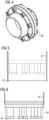
- Figure 5 illustrates another embodiment, where a cover 70 is positioned inside the container 20 enclosing and covering the first ports 30 and the container interface 50A.
- the cover 70 shields the first ports 30 e.g., during transfer and mounting of the container 20, and are optionally also positioned during the use, such as during the generation of Hydrogen.
- the cover 70 thus could form a seal towards externals.
- the cover 70 then may be removed when access to the first ports 30 is required.
- the bottom opening 40 during e.g., transfer of the container 20 may be closed by a cover plate (not shown in the figure).
- the 'plug-and-play' compartment 100 could enclose the first ports 30 and container interface 50A within a cover 70 could alternatively be connected the outside the container 20.
- Figure 6 illustrates an embodiment where the connections are positioned at the outside of the bottom of the container 20
- the second ports 30' could be positioned at the lower side of the platform 10 surface, the container connections 20 reaching through an opening 40 in the platform surface 10.
- the second ports 30' could be covered with temporary covers when not in contact with container 20 first ports 30, such as by positioning a small temporary container to cover them, or a box or by other means positioned on top of the second ports 30'. This protects the inner parts from the environmental conditions.
- the compartment 100 could be monitored by temperature sensors, thermal camera, gas sensor/alarm, humidity sensor etc.
- Figure 7 shows a flow chart of the method to link a container 20 in connection to a wind turbine 1.
- the method including to 200 provide linkage means first ports 30 within a compartment 100, to 210 open or remove a cover 70 of the compartment 100, to 220 link the first ports 30 to the second ports 30', and to 230 replace or close the cover 70 to seal the compartment 100.
Landscapes
- Engineering & Computer Science (AREA)
- Chemical & Material Sciences (AREA)
- Power Engineering (AREA)
- Life Sciences & Earth Sciences (AREA)
- Sustainable Development (AREA)
- Sustainable Energy (AREA)
- Combustion & Propulsion (AREA)
- Mechanical Engineering (AREA)
- General Engineering & Computer Science (AREA)
- Chemical Kinetics & Catalysis (AREA)
- Electrochemistry (AREA)
- Filling Or Discharging Of Gas Storage Vessels (AREA)
Priority Applications (3)
| Application Number | Priority Date | Filing Date | Title |
|---|---|---|---|
| EP22207119.3A EP4368829A1 (de) | 2022-11-14 | 2022-11-14 | Modularer plug and play behälter - insbesondere für eine wasserstoffproduktionsanlage in verbindung mit einer windturbine |
| PCT/EP2023/078986 WO2024104693A1 (en) | 2022-11-14 | 2023-10-18 | Modular plug and play container – particular for a hydrogen production plant in connection to a wind turbine |
| EP23790026.1A EP4573284A1 (de) | 2022-11-14 | 2023-10-18 | Modularer plug-and-play-behälter speziell für eine wasserstoffproduktionsanlage in verbindung mit einer windturbine |
Applications Claiming Priority (1)
| Application Number | Priority Date | Filing Date | Title |
|---|---|---|---|
| EP22207119.3A EP4368829A1 (de) | 2022-11-14 | 2022-11-14 | Modularer plug and play behälter - insbesondere für eine wasserstoffproduktionsanlage in verbindung mit einer windturbine |
Publications (1)
| Publication Number | Publication Date |
|---|---|
| EP4368829A1 true EP4368829A1 (de) | 2024-05-15 |
Family
ID=84389071
Family Applications (2)
| Application Number | Title | Priority Date | Filing Date |
|---|---|---|---|
| EP22207119.3A Withdrawn EP4368829A1 (de) | 2022-11-14 | 2022-11-14 | Modularer plug and play behälter - insbesondere für eine wasserstoffproduktionsanlage in verbindung mit einer windturbine |
| EP23790026.1A Withdrawn EP4573284A1 (de) | 2022-11-14 | 2023-10-18 | Modularer plug-and-play-behälter speziell für eine wasserstoffproduktionsanlage in verbindung mit einer windturbine |
Family Applications After (1)
| Application Number | Title | Priority Date | Filing Date |
|---|---|---|---|
| EP23790026.1A Withdrawn EP4573284A1 (de) | 2022-11-14 | 2023-10-18 | Modularer plug-and-play-behälter speziell für eine wasserstoffproduktionsanlage in verbindung mit einer windturbine |
Country Status (2)
| Country | Link |
|---|---|
| EP (2) | EP4368829A1 (de) |
| WO (1) | WO2024104693A1 (de) |
Citations (5)
| Publication number | Priority date | Publication date | Assignee | Title |
|---|---|---|---|---|
| US20060137348A1 (en) * | 2001-07-17 | 2006-06-29 | Pas Peter Alexander J | Mobile wind and solar energy aggregate |
| KR20120038062A (ko) * | 2010-10-13 | 2012-04-23 | 삼성중공업 주식회사 | 해상용 풍력발전설비를 이용한 수소생산 플랜트 |
| US20150108764A1 (en) * | 2013-10-17 | 2015-04-23 | Siemens Aktiengesellschaft | Single piece electric assembly for connecting an off-shore wind turbine with an electric subsea cable, wind turbine, wind turbine cluster and method for mounting such an electric assembly to a wind turbine tower |
| CN215628320U (zh) * | 2021-08-20 | 2022-01-25 | 上海惠生海洋工程有限公司 | 一种浮式风电制氢装置 |
| EP4067534A1 (de) * | 2021-03-30 | 2022-10-05 | Siemens Gamesa Renewable Energy A/S | Offshore-kraftwerk für erneuerbare energien |
-
2022
- 2022-11-14 EP EP22207119.3A patent/EP4368829A1/de not_active Withdrawn
-
2023
- 2023-10-18 WO PCT/EP2023/078986 patent/WO2024104693A1/en not_active Ceased
- 2023-10-18 EP EP23790026.1A patent/EP4573284A1/de not_active Withdrawn
Patent Citations (5)
| Publication number | Priority date | Publication date | Assignee | Title |
|---|---|---|---|---|
| US20060137348A1 (en) * | 2001-07-17 | 2006-06-29 | Pas Peter Alexander J | Mobile wind and solar energy aggregate |
| KR20120038062A (ko) * | 2010-10-13 | 2012-04-23 | 삼성중공업 주식회사 | 해상용 풍력발전설비를 이용한 수소생산 플랜트 |
| US20150108764A1 (en) * | 2013-10-17 | 2015-04-23 | Siemens Aktiengesellschaft | Single piece electric assembly for connecting an off-shore wind turbine with an electric subsea cable, wind turbine, wind turbine cluster and method for mounting such an electric assembly to a wind turbine tower |
| EP4067534A1 (de) * | 2021-03-30 | 2022-10-05 | Siemens Gamesa Renewable Energy A/S | Offshore-kraftwerk für erneuerbare energien |
| CN215628320U (zh) * | 2021-08-20 | 2022-01-25 | 上海惠生海洋工程有限公司 | 一种浮式风电制氢装置 |
Also Published As
| Publication number | Publication date |
|---|---|
| WO2024104693A1 (en) | 2024-05-23 |
| EP4573284A1 (de) | 2025-06-25 |
Similar Documents
| Publication | Publication Date | Title |
|---|---|---|
| CN102906420B (zh) | 用于风轮机的包括侧单元的机舱 | |
| CN104578139B (zh) | 用于离岸风力涡轮机的单件电组件以及安装其的方法 | |
| US9395021B2 (en) | System and method for interconnecting umbilicals for conveying energy, fluids and/or data in a marine environment | |
| CN202120625U (zh) | 用于核电设施的装置 | |
| EP2732125A1 (de) | Unterwassertransformator | |
| EP4368829A1 (de) | Modularer plug and play behälter - insbesondere für eine wasserstoffproduktionsanlage in verbindung mit einer windturbine | |
| US9163512B2 (en) | Bladeless turbine | |
| CN107192503B (zh) | 一种高压电缆中间接头环境水位模拟试验装置 | |
| NO347131B1 (en) | A high voltage offshore power plant power distribution assembly, a high voltage subsea transformer, and a appurtenant installation method | |
| CN110011208A (zh) | 一种方便检修的地埋变电站 | |
| CN201368051Y (zh) | 一种泵引出电缆线接头的密封装置 | |
| US20230383726A1 (en) | Hydrogen manifold for wind turbines | |
| CN107332146A (zh) | 一种新型海上风电安装船gis模块安装方法 | |
| EP1594197B1 (de) | Unter Druck stehende elektrische Verbindungsvorrichtung | |
| ES2932652T3 (es) | Mejoras relativas a generadores eléctricos en aerogeneradores | |
| CN107255103B (zh) | 整体密封型液压泵站 | |
| CN219919189U (zh) | 一种具有分体式接线盒的电加热器 | |
| CN224174222U (zh) | 一种海上风电机组风冷散热电缆保护罩结构 | |
| RU2664604C1 (ru) | Многофункциональный интегрируемый мотор-компрессор для транспортировки флюидов по подводным и континентальным трубопроводам | |
| CN222231777U (zh) | 一种防冻检修水表箱 | |
| CN213906200U (zh) | 一种火力发电厂电气接线绝缘保护装置 | |
| CN111980671A (zh) | 水下电子模块 | |
| CN221120124U (zh) | 燃气轮机主机箱装体 | |
| RU234371U1 (ru) | Гидравлический генератор | |
| KR880001856Y1 (ko) | 수로관식 수력 발전장치 |
Legal Events
| Date | Code | Title | Description |
|---|---|---|---|
| PUAI | Public reference made under article 153(3) epc to a published international application that has entered the european phase |
Free format text: ORIGINAL CODE: 0009012 |
|
| STAA | Information on the status of an ep patent application or granted ep patent |
Free format text: STATUS: THE APPLICATION HAS BEEN PUBLISHED |
|
| AK | Designated contracting states |
Kind code of ref document: A1 Designated state(s): AL AT BE BG CH CY CZ DE DK EE ES FI FR GB GR HR HU IE IS IT LI LT LU LV MC ME MK MT NL NO PL PT RO RS SE SI SK SM TR |
|
| STAA | Information on the status of an ep patent application or granted ep patent |
Free format text: STATUS: THE APPLICATION IS DEEMED TO BE WITHDRAWN |
|
| 18D | Application deemed to be withdrawn |
Effective date: 20241116 |