EP4369117A1 - Dispositif de sécurité - Google Patents
Dispositif de sécurité Download PDFInfo
- Publication number
- EP4369117A1 EP4369117A1 EP22207094.8A EP22207094A EP4369117A1 EP 4369117 A1 EP4369117 A1 EP 4369117A1 EP 22207094 A EP22207094 A EP 22207094A EP 4369117 A1 EP4369117 A1 EP 4369117A1
- Authority
- EP
- European Patent Office
- Prior art keywords
- telegram
- safety
- master
- sensor
- arrangement
- Prior art date
- Legal status (The legal status is an assumption and is not a legal conclusion. Google has not performed a legal analysis and makes no representation as to the accuracy of the status listed.)
- Pending
Links
Images


Classifications
-
- G—PHYSICS
- G05—CONTROLLING; REGULATING
- G05B—CONTROL OR REGULATING SYSTEMS IN GENERAL; FUNCTIONAL ELEMENTS OF SUCH SYSTEMS; MONITORING OR TESTING ARRANGEMENTS FOR SUCH SYSTEMS OR ELEMENTS
- G05B19/00—Program-control systems
- G05B19/02—Program-control systems electric
- G05B19/04—Program control other than numerical control, i.e. in sequence controllers or logic controllers
- G05B19/042—Program control other than numerical control, i.e. in sequence controllers or logic controllers using digital processors
- G05B19/0428—Safety, monitoring
-
- G—PHYSICS
- G05—CONTROLLING; REGULATING
- G05B—CONTROL OR REGULATING SYSTEMS IN GENERAL; FUNCTIONAL ELEMENTS OF SUCH SYSTEMS; MONITORING OR TESTING ARRANGEMENTS FOR SUCH SYSTEMS OR ELEMENTS
- G05B19/00—Program-control systems
- G05B19/02—Program-control systems electric
- G05B19/04—Program control other than numerical control, i.e. in sequence controllers or logic controllers
- G05B19/042—Program control other than numerical control, i.e. in sequence controllers or logic controllers using digital processors
- G05B19/0421—Multiprocessor system
-
- G—PHYSICS
- G05—CONTROLLING; REGULATING
- G05B—CONTROL OR REGULATING SYSTEMS IN GENERAL; FUNCTIONAL ELEMENTS OF SUCH SYSTEMS; MONITORING OR TESTING ARRANGEMENTS FOR SUCH SYSTEMS OR ELEMENTS
- G05B9/00—Safety arrangements
- G05B9/02—Safety arrangements electric
- G05B9/03—Safety arrangements electric with multiple-channel loop, i.e. redundant control systems
-
- G—PHYSICS
- G05—CONTROLLING; REGULATING
- G05B—CONTROL OR REGULATING SYSTEMS IN GENERAL; FUNCTIONAL ELEMENTS OF SUCH SYSTEMS; MONITORING OR TESTING ARRANGEMENTS FOR SUCH SYSTEMS OR ELEMENTS
- G05B2219/00—Program-control systems
- G05B2219/10—Plc systems
- G05B2219/11—Plc I-O input output
- G05B2219/1113—Address setting
-
- G—PHYSICS
- G05—CONTROLLING; REGULATING
- G05B—CONTROL OR REGULATING SYSTEMS IN GENERAL; FUNCTIONAL ELEMENTS OF SUCH SYSTEMS; MONITORING OR TESTING ARRANGEMENTS FOR SUCH SYSTEMS OR ELEMENTS
- G05B2219/00—Program-control systems
- G05B2219/20—Pc systems
- G05B2219/22—Pc multi processor system
- G05B2219/2231—Leader-follower
Definitions
- the invention relates to a safety arrangement and a method for operating a safety arrangement.
- Such safety arrangements have a safety sensor that is designed to monitor objects in a monitoring area.
- the safety sensor For use in the field of safety technology, the safety sensor has a fail-safe structure.
- the safety sensor generally forms a contactless protective device that is used in particular to monitor a danger area of a system.
- the safety sensor registers a dangerous intervention in the monitoring area, a safety function is triggered by this safety sensor, which puts the system into a safe state.
- the safety sensor is connected to a control system that controls the system via a data connection so that data can be exchanged between them.
- Such a data connection can be formed by a secure fieldbus.
- the data connection can also be established via an IO-Link communication protocol.
- IO-Link systems do not form a bus system, but rather a point-to-point connection between the respective participants.
- the controller generally forms a master and the safety sensor a slave of the entire safety arrangement.
- a problem with such data connections is generally low transmission rates, which lead to undesirably high response times of the overall system.
- a general problem with IO-Link systems is the high demand on the response time of a slave, i.e. the safety sensor, to a request from the master.
- the response time must be less than ten times the value of a bit time, i.e. the transmission time for one bit.
- the invention is based on the object of providing a safety arrangement and a method that enables short reaction times during data exchange between a master and a safety sensor via an IO-Link communication protocol.
- the invention relates to a method for operating a safety arrangement with a master and a safety sensor forming a slave, which exchange data via an IO-Link communication protocol in which the safety sensor sends an output telegram to the master in response to a request telegram from the master.
- the safety sensor has a multi-channel computer structure in which output telegrams are generated, whereby an output telegram generated and temporarily stored in the multi-channel computer structure before receiving a request telegram is sent to the master.
- the invention further relates to a corresponding method.
- the response time to a telegram request from the master can be significantly shortened compared to known systems working with IO-Link.
- an output telegram is prepared in advance in the multi-channel computer structure of the safety sensor, i.e. generated and buffered. If a request telegram is then sent from the master to the safety sensor, the output telegram is already available in the buffer and can be sent to the master immediately, resulting in a very short response time.
- the master's request telegram can then be checked after the distributed output telegram has been sent in the multi-channel computer structure of the safety sensor. A new output telegram is then generated.
- a new output telegram is generated as a response to the request telegram and temporarily stored. This temporarily stored new output telegram is sent to the master after receiving the next request telegram.
- an output telegram is prepared and temporarily stored in the multi-channel computer structure of the safety sensor, regardless of the receipt of a request telegram.
- This prepared output telegram is sent to the master as soon as a request telegram is received from the master.
- the new output telegram is generated and buffered in good time before the next request telegram is received, so that the new output telegram can also be sent to the master immediately after the next request telegram is received.
- fail-safe data transmission takes place between the master and the safety sensor.
- the data exchange between the master and the safety sensor is particularly advantageous via an IO-Link safety communication protocol.
- safety-relevant data is advantageously transmitted with a data telegram in the form of a request telegram or output telegram, which is secured by a checksum, in particular a CRC signature, which is part of the data telegram.
- the data telegram can be used to transmit non-security-relevant data that is not secured by a checksum, in particular a CRC signature.
- the data telegram has a control byte with a counter value of a counter.
- the counter is preferably a 3-bit counter.
- the counter is managed by the master.
- a count value transmitted in a request telegram is inverted in the safety sensor and sent back to the master.
- This port number is assigned by the master and represents a unique identification of the slave from the master's perspective.
- the port number is transmitted from the master to the slave together with other authentication data in a so-called verify record. This means that the port number is already known on the slave before the start of secure, cyclic telegram traffic.
- the output telegram in response to the first request telegram, expediently contains safety-relevant data corresponding to a safe state of the safety sensor.
- the multi-channel computer structure of the safety sensor is designed as a two-channel system and has two computer units.
- the two aforementioned computer units are present as different cores in a multicore controller within a housing.
- Sensor signals from the safety sensor are evaluated in the computer units to generate an object detection signal.
- the object detection signal indicates whether there is a dangerous object intrusion in the monitoring area monitored by the safety sensor. If such an object intrusion occurs, an object detection signal is generated in such a way that a safety function is triggered, for example in such a way that the system monitored by the safety sensor, whose control system forms the master, is shut down.
- the two computer units check the request telegrams received from the master and generate the output telegrams. It is advantageous if one of the computer units takes over communication with the master, i.e. request telegrams are received and output telegrams sent only with the first computer unit.
- the multi-channel computer unit has a communication computer unit in addition to the two computer units, whereby only the communication computer unit is used to receive request telegrams and send output telegrams.
- the communication computer unit is solely responsible for communication between the safety sensor and the master, which ensures sufficiently short response times when exchanging data.
- the communication computer unit is also another core, in addition to the two aforementioned cores for the computer units for evaluating the sensor signals, in a multicore controller within a housing.
- the safety sensor is an optical sensor.
- the safety sensor is a light curtain, an area distance sensor or a camera sensor.
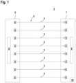
- Figure 1 shows a first embodiment of a safety sensor 1 in the form of a light curtain, by means of which a flat protective field 2 is monitored.
- the light curtain comprises an arrangement of transmitters 4 emitting light beams 3, which are cyclically activated one after the other by a control unit (not shown).
- the transmitters 4 and the control unit are integrated in a transmitter unit 5 with a first housing.
- the light curtain further comprises an arrangement of receivers 6 for receiving light beams 3.
- the receivers 6 are in a receiver unit 7 with a second housing integrated.
- the transmitters 4 are controlled by a transmitter control 8.
- the receivers 6 are assigned an evaluation unit 9 for controlling the receiver operation and for evaluating the received signals present at the outputs of the receivers 6.
- the evaluation unit 9 has a redundant structure.
- the evaluation unit 9 consists of a multi-channel computer structure.
- the light curtain monitors a protective field 2 which is formed by the area between the two housings.
- Each transmitter 4 is assigned a receiver 6 so that when the protective field 2 is free, the light beams 3 emitted by the transmitter 4 strike the receiver 6.
- One transmitter 4 and the assigned receiver 6 each define a beam axis of the light curtain 1, the direction of the beam axis being given by the light beams 3 of the respective transmitter 4. If an object enters the protective field 2, the beam path of the light beams 3 of at least one transmitter 4, ie at least one beam axis, is interrupted.
- a fail-safe switching signal is generated as an object detection signal depending on the signals from the sensor unit, the switching states of which indicate whether an object is in the protective field 2 or not.
- the switching signal is output via a safety switching output 10, which is advantageously designed with multiple channels.
- the safety switching output 10 is switched on according to the current switching state of the switching signal. If an object enters the protective field 2, the safety switching output 10 is switched off.
- the light curtain can be designed as a reflection light curtain.
- Figure 2 shows an embodiment of a safety sensor 1 in the form of an area distance sensor.
- the area distance sensor has a distance sensor operating according to a pulse transit time method with a transmitting element 12 emitting transmitted light beams 11 and a receiving light beam 13 receiving receiving element 14, wherein the distance of the target object 15 is determined from the light travel time to a target object 15 and back to the area distance sensor.
- the transmitting element 12 and the receiving element 14 are mounted by means of a holder in a measuring head 16, the outer surface of which forms an exit window for the transmitted light beams 11 and received light beams 13.
- the measuring head 16 is rotatably mounted on a base 17. By means of a drive (not shown), the measuring head 16 is set in a rotary movement about a rotation axis D, whereby the transmitted light beams 11 periodically sweep over a flat protective field 2.
- the area distance sensor can be designed such that the transmitting element 12 and receiving element 14 are arranged stationary in a housing.
- the transmitted light beams 11 are then periodically deflected by a motor-driven deflection unit.
- Figure 3 shows an embodiment of a security sensor 1 in the form of a camera sensor, which has an image sensor 18 and an illumination unit 19.
- the image sensor 18 can have a linear or matrix arrangement of pixels.
- the image sensor 18 can be formed by a CCD or CMOS array.
- the safety sensors 1 also comply with the Figures 2 and 3 an evaluation unit 9 and a safety switching output 10.
- FIG 4 shows schematically an embodiment of the safety arrangement 20 according to the invention.
- the safety arrangement 20 comprises as safety sensor 1 a surface distance sensor with which a danger area 21 on a system 22 is monitored.
- the system 22 is controlled by a controller which forms a master 23 and to which the safety sensor 1 is connected as a slave via a data connection 24 is connected.
- the safety sensor 1 forms a fail safe (FS) sensor
- the master 23 is a fail safe (FS) master 23.
- data is exchanged via the data connections 24 via an IO-Link communication protocol, advantageously via an IO-Link Safety communication protocol.
- Figure 5 shows schematically the IO-Link specification with the required maximum response time t A for data transmission.
- T bit is the transmission time for 1 bit.
- the UART frames may be separated on the master side 23 by a maximum time of t 1 and on the slave side by a maximum time of t 2.
- the time t A of a transmission sequence may be a maximum of 10 x T bits .
- FIGS. 6a, 6b show the structures of the data telegrams that are transmitted via IO-Link in the safety arrangement 20 according to the invention.
- Figure 6a shows a request telegram 25 sent by the master 23, with which safety-relevant data (FS-PDout) is transmitted to the slave, which is secured with a CRC signature.
- the request telegram 25 contains a port number (PortNum) that identifies the respective slave and is assigned by the master 23.
- PortNum port number
- control byte contains a counter value of a 3-bit counter.
- non-safety-relevant data output PD
- Figure 6b shows a response telegram 26 sent by the slave.
- the response telegram 26 has a corresponding Structure.
- secured safety-relevant data (FS PDein) and unsecured non-safety-relevant data (input PD) are sent using a CRC signature.
- the status byte corresponding to the control byte contains a value of a 3-bit counter.
- the counter is advantageously managed by the master 23.
- a count value transmitted in a request telegram 25 is inverted in the safety sensor 1 and sent back to the master 23.
- Figure 7 shows a functional diagram of the safety arrangement 20 with the master 23 and a safety sensor 1, which has two computer units 27a, 27b as a multi-channel computer structure.
- the computer units 27a, 27b form the evaluation unit 9 of the safety sensor 1 and are used to evaluate the sensor signals and to generate the object detection signal.
- the computer units 27a, 27b take over the IO-Link data communication and evaluation, whereby only the first computer unit 27a communicates with the master 23.
- a prepared output telegram 26 i.e. previously created in accordance with the safety requirements, on two channels and temporarily stored, is sent back to the master 23 (send prepared FSoutput).
- the received request telegram 25 is then checked in the first computer unit 27a (check FSinput1).
- the request telegram is then forwarded to the second computer unit 27b (transmit FSinput).
- the request telegram is also checked in the second computer unit 27b (check FSInput2).
- a new output telegram 26 is then generated on two channels, first in the second computer unit 27b (create FSOutput1), with the result then being transmitted to the first computer unit 27a (transmit FSOutput1) and then the first computer unit 27a continues to process the Output telegram 26 is generated, whereby the finished output telegram 26 is then temporarily stored (create and store FSOutput2).
- the output telegram 26 prepared in this way is sent to the master 23 as soon as a new request telegram is received.
- the generation of a new output telegram 26 is linked to the sending of the first output telegram 26 after receipt of the request telegram 25.
- FIGS 8a , 8b show a variant of the embodiment according to Figure 7 , in which the generation of a new output telegram 26 is decoupled from the reception of the request telegram 25 and the subsequent sending of the first output telegram 26.
- Figure 8a shows the sending of a prepared output telegram 26 after receiving a request telegram 25 from the master 23 and subsequent checking of the request telegram 25 in both computer units 27a, 27b analogous to the embodiment according to Figure 7 .
- Figure 8b shows the preparation of the next output telegram 26 independent of the receipt of the request telegram 25.
- the generation of the output telegram 26 is initiated by a timer (timer event).
- the further generation of the output telegram 26 is carried out analogously to the embodiment according to Figure 7 .
- FIG 9 shows a variant of the embodiment according to Figure 7 .
- the multi-channel computer structure of the safety sensor 1 has a communication computer unit 28 in addition to the first computer unit 27a and the second computer unit 27b.
- the communication computer unit 28 handles the communication with the master 23 via IO-Link.
- Figure 10 shows a functional diagram for the safety arrangement 20 according to Figure 9 .
- the communication computer unit 28 receives the request telegrams 25 and temporarily stores and sends the output telegrams 26.
- the computer units 27a, 27b check the request telegrams 25.
- the individual process steps correspond to the embodiment according to Figure 7 .
- FIGS. 11a to 11c show exemplary time diagrams for the safety arrangement 20 according to Figure 10 11a shows the timing behavior of the computing units 27a, 27b.
- Figure 11b shows the timing behavior of the communication computer unit 28.
- Figure 12 shows a first embodiment of the evaluation unit 9 of the safety sensor 1.
- the evaluation unit 9 is designed as a multi-core CPU 29, which has several cores 29a-c, ie computer cores.
- cores 29a-c ie computer cores.
- Three cores 29a-c are shown as an example, although a different number of cores 29a-c is of course possible.
- the multi-core CPU 29 is arranged in a housing.
- Figure 13 shows another embodiment of the evaluation unit 9 of the safety sensor 1.
- the embodiment of the Figure 13 differs from the design of the Figure 12 only because the multi-core CPU 29 has the communication computer unit 28 as an additional core unit.
Landscapes
- Physics & Mathematics (AREA)
- General Physics & Mathematics (AREA)
- Engineering & Computer Science (AREA)
- Automation & Control Theory (AREA)
- Arrangements For Transmission Of Measured Signals (AREA)
Priority Applications (1)
| Application Number | Priority Date | Filing Date | Title |
|---|---|---|---|
| EP22207094.8A EP4369117A1 (fr) | 2022-11-14 | 2022-11-14 | Dispositif de sécurité |
Applications Claiming Priority (1)
| Application Number | Priority Date | Filing Date | Title |
|---|---|---|---|
| EP22207094.8A EP4369117A1 (fr) | 2022-11-14 | 2022-11-14 | Dispositif de sécurité |
Publications (1)
| Publication Number | Publication Date |
|---|---|
| EP4369117A1 true EP4369117A1 (fr) | 2024-05-15 |
Family
ID=84360789
Family Applications (1)
| Application Number | Title | Priority Date | Filing Date |
|---|---|---|---|
| EP22207094.8A Pending EP4369117A1 (fr) | 2022-11-14 | 2022-11-14 | Dispositif de sécurité |
Country Status (1)
| Country | Link |
|---|---|
| EP (1) | EP4369117A1 (fr) |
Citations (4)
| Publication number | Priority date | Publication date | Assignee | Title |
|---|---|---|---|---|
| US20170220502A1 (en) * | 2016-01-29 | 2017-08-03 | Analog Devices, Inc. | Gpio-to-gpio communication on a multi-node daisy-chained network |
| DE102016114600B3 (de) * | 2016-08-05 | 2017-12-14 | Sick Ag | IO-Link-fähiger Sensor und Verfahren zum Kommunizieren |
| US20190041819A1 (en) * | 2011-10-05 | 2019-02-07 | Opteon Corporation | Methods, apparatus, and systems for monitoring and/or controlling dynamic environments |
| US20210314186A1 (en) * | 2018-10-31 | 2021-10-07 | Mitsubishi Electric Corporation | Communication system, communication apparatus, communication method, and program |
-
2022
- 2022-11-14 EP EP22207094.8A patent/EP4369117A1/fr active Pending
Patent Citations (4)
| Publication number | Priority date | Publication date | Assignee | Title |
|---|---|---|---|---|
| US20190041819A1 (en) * | 2011-10-05 | 2019-02-07 | Opteon Corporation | Methods, apparatus, and systems for monitoring and/or controlling dynamic environments |
| US20170220502A1 (en) * | 2016-01-29 | 2017-08-03 | Analog Devices, Inc. | Gpio-to-gpio communication on a multi-node daisy-chained network |
| DE102016114600B3 (de) * | 2016-08-05 | 2017-12-14 | Sick Ag | IO-Link-fähiger Sensor und Verfahren zum Kommunizieren |
| US20210314186A1 (en) * | 2018-10-31 | 2021-10-07 | Mitsubishi Electric Corporation | Communication system, communication apparatus, communication method, and program |
Non-Patent Citations (1)
| Title |
|---|
| IO-LINK COMMUNITY: "IO-Link Safety System Extensions", 30 November 2016 (2016-11-30), pages 1 - 147, XP093042416, Retrieved from the Internet <URL:https://io-link.com/share/Downloads/System-Extensions/IO-Link_Safety_System-Extensions_10092_dV094_Nov16.pdf> [retrieved on 20230426] * |
Similar Documents
| Publication | Publication Date | Title |
|---|---|---|
| EP2014025B1 (fr) | Unité d'interface et système de communication à structure maître-esclave | |
| DE19939568C1 (de) | Verfahren zur Einstellung einer Datenübertragungsrate in einem Feldbussystem | |
| EP1297394B1 (fr) | Systeme de commande redondant avec calculateur pilote, et unite peripherique pour un tel systeme de commande | |
| EP2866387B1 (fr) | Système de bus et procédé de fonctionnement d'un tel système de bus | |
| EP1869836B1 (fr) | Unite maitre, systeme de communication et procede pour les faire fonctionner | |
| DE19939567A1 (de) | Vorrichtung zum Steuern von sicherheitskritischen Prozessen | |
| DE69021186T2 (de) | "Master-Slave" industrielles Netzwerk mit Tokenübergabe. | |
| EP1469440B1 (fr) | Procédé de transmission d'information de sécurité | |
| DE19633744C2 (de) | Ringgraph in einem elektrischen Antriebssystem | |
| EP2145430B1 (fr) | Procédé et système de transmission cyclique fiable de données de processus | |
| DE19922171B4 (de) | Kommunikationssystem mit einem Kommunikationsbus | |
| EP1054309B1 (fr) | Procédé et appareil pour la transmission sûre de données par l'intermédiaire d'un système de bus | |
| DE2701925C3 (de) | Fahrzeugsteuerung mit zwei Bordrechnern | |
| DE10337699B4 (de) | Verfahren und Vorrichtung zur Übertragung von Daten über ein Busnetz unter Verwendung des Broadcast-Prinzip | |
| EP3436383B1 (fr) | Ascenseur comprenant une unite de commande centrale et plusieurs appareils de champ communiquant selon un procede de trame unique | |
| DE102006054124B4 (de) | Verfahren und System zur sicheren Datenübertragung | |
| EP0978775B1 (fr) | Méthode de transmission sûre de données entre une commande numérique et un appareil à distance | |
| EP1064590B1 (fr) | Telegramme de donnees abrege d'un systeme d'automatisation | |
| DE112012003005T5 (de) | Netzwerk für die Übertragung von Informationen und entsprechender Netzwerkknoten | |
| EP4369117A1 (fr) | Dispositif de sécurité | |
| DE102011051629B3 (de) | Sicherheitsbussystem | |
| EP1283468A2 (fr) | Unité centrale pour un système d'automatisation redondant | |
| EP1227406A1 (fr) | Dispositif d'émission et de réception avec des moyens de gestion d'erreur | |
| EP3104558B1 (fr) | Interface réseau, réseau et procédé de transmission de données dans le réseau | |
| EP3977211B1 (fr) | Système de commande et procédé pour faire fonctionner un système de commande |
Legal Events
| Date | Code | Title | Description |
|---|---|---|---|
| PUAI | Public reference made under article 153(3) epc to a published international application that has entered the european phase |
Free format text: ORIGINAL CODE: 0009012 |
|
| STAA | Information on the status of an ep patent application or granted ep patent |
Free format text: STATUS: REQUEST FOR EXAMINATION WAS MADE |
|
| 17P | Request for examination filed |
Effective date: 20230619 |
|
| AK | Designated contracting states |
Kind code of ref document: A1 Designated state(s): AL AT BE BG CH CY CZ DE DK EE ES FI FR GB GR HR HU IE IS IT LI LT LU LV MC ME MK MT NL NO PL PT RO RS SE SI SK SM TR |
|
| P01 | Opt-out of the competence of the unified patent court (upc) registered |
Effective date: 20240521 |
|
| STAA | Information on the status of an ep patent application or granted ep patent |
Free format text: STATUS: EXAMINATION IS IN PROGRESS |
|
| 17Q | First examination report despatched |
Effective date: 20250901 |