EP4369302A1 - Verfahren und systeme zur korrektur von metallartefakten - Google Patents
Verfahren und systeme zur korrektur von metallartefakten Download PDFInfo
- Publication number
- EP4369302A1 EP4369302A1 EP23205813.1A EP23205813A EP4369302A1 EP 4369302 A1 EP4369302 A1 EP 4369302A1 EP 23205813 A EP23205813 A EP 23205813A EP 4369302 A1 EP4369302 A1 EP 4369302A1
- Authority
- EP
- European Patent Office
- Prior art keywords
- data
- projection data
- target
- image
- determining
- Prior art date
- Legal status (The legal status is an assumption and is not a legal conclusion. Google has not performed a legal analysis and makes no representation as to the accuracy of the status listed.)
- Pending
Links
Images






Classifications
-
- G—PHYSICS
- G06—COMPUTING OR CALCULATING; COUNTING
- G06T—IMAGE DATA PROCESSING OR GENERATION, IN GENERAL
- G06T12/00—Tomographic reconstruction from projections
- G06T12/10—Image preprocessing, e.g. calibration, positioning of sources or scatter correction
-
- G—PHYSICS
- G06—COMPUTING OR CALCULATING; COUNTING
- G06T—IMAGE DATA PROCESSING OR GENERATION, IN GENERAL
- G06T12/00—Tomographic reconstruction from projections
- G06T12/30—Image post-processing, e.g. metal artefact correction
-
- G—PHYSICS
- G06—COMPUTING OR CALCULATING; COUNTING
- G06T—IMAGE DATA PROCESSING OR GENERATION, IN GENERAL
- G06T5/00—Image enhancement or restoration
-
- G—PHYSICS
- G06—COMPUTING OR CALCULATING; COUNTING
- G06T—IMAGE DATA PROCESSING OR GENERATION, IN GENERAL
- G06T5/00—Image enhancement or restoration
- G06T5/20—Image enhancement or restoration using local operators
-
- G—PHYSICS
- G06—COMPUTING OR CALCULATING; COUNTING
- G06T—IMAGE DATA PROCESSING OR GENERATION, IN GENERAL
- G06T5/00—Image enhancement or restoration
- G06T5/70—Denoising; Smoothing
-
- G—PHYSICS
- G06—COMPUTING OR CALCULATING; COUNTING
- G06T—IMAGE DATA PROCESSING OR GENERATION, IN GENERAL
- G06T5/00—Image enhancement or restoration
- G06T5/77—Retouching; Inpainting; Scratch removal
-
- G—PHYSICS
- G06—COMPUTING OR CALCULATING; COUNTING
- G06T—IMAGE DATA PROCESSING OR GENERATION, IN GENERAL
- G06T7/00—Image analysis
- G06T7/10—Segmentation; Edge detection
- G06T7/136—Segmentation; Edge detection involving thresholding
-
- G—PHYSICS
- G06—COMPUTING OR CALCULATING; COUNTING
- G06T—IMAGE DATA PROCESSING OR GENERATION, IN GENERAL
- G06T2207/00—Indexing scheme for image analysis or image enhancement
- G06T2207/10—Image acquisition modality
- G06T2207/10072—Tomographic images
- G06T2207/10081—Computed x-ray tomography [CT]
-
- G—PHYSICS
- G06—COMPUTING OR CALCULATING; COUNTING
- G06T—IMAGE DATA PROCESSING OR GENERATION, IN GENERAL
- G06T2207/00—Indexing scheme for image analysis or image enhancement
- G06T2207/10—Image acquisition modality
- G06T2207/10116—X-ray image
-
- G—PHYSICS
- G06—COMPUTING OR CALCULATING; COUNTING
- G06T—IMAGE DATA PROCESSING OR GENERATION, IN GENERAL
- G06T2207/00—Indexing scheme for image analysis or image enhancement
- G06T2207/20—Special algorithmic details
- G06T2207/20081—Training; Learning
-
- G—PHYSICS
- G06—COMPUTING OR CALCULATING; COUNTING
- G06T—IMAGE DATA PROCESSING OR GENERATION, IN GENERAL
- G06T2207/00—Indexing scheme for image analysis or image enhancement
- G06T2207/30—Subject of image; Context of image processing
- G06T2207/30004—Biomedical image processing
-
- G—PHYSICS
- G06—COMPUTING OR CALCULATING; COUNTING
- G06T—IMAGE DATA PROCESSING OR GENERATION, IN GENERAL
- G06T2207/00—Indexing scheme for image analysis or image enhancement
- G06T2207/30—Subject of image; Context of image processing
- G06T2207/30241—Trajectory
-
- G—PHYSICS
- G06—COMPUTING OR CALCULATING; COUNTING
- G06T—IMAGE DATA PROCESSING OR GENERATION, IN GENERAL
- G06T2211/00—Image generation
- G06T2211/40—Computed tomography
- G06T2211/441—AI-based methods, deep learning or artificial neural networks
Definitions
- the present disclosure relates to an image processing technology field, in particular, relates to systems, methods, and mediums for metal artifacts correction.
- metal to rays e.g., X-rays
- a proportion of the rays absorbed by the metal is relatively large, and detectors receive few rays. Therefore, in clinical applications using radiographic imaging, a metal implant (e.g., metal dentures, bone nails, etc.) carried by patients absorbs the rays, resulting in incomplete data collection of the metal implant, and causing serious metal artifacts (i.e., stripe artifacts) in reconstructed images, which affects diagnostic accuracy greatly.
- metal implant e.g., metal dentures, bone nails, etc.
- the system may include at least one storage medium including a set of instructions; and at least one processor in communication with the at least one storage medium, wherein when executing the set of instructions, the at least one processor is directed to cause the system to perform operations including: obtaining an image to be processed including a metal portion; determining initial projection data by performing data restoration on the metal portion of the image to be processed; determining target projection data by filtering the initial projection data; and determining a target image based on the target projection data.
- the determining the target projection data by filtering the initial projection data may include obtaining the target projection data by performing low-pass filtering on the initial projection data.
- the obtaining the target projection data by performing the low-pass filtering on the initial projection data may include obtaining restoration data corresponding to the metal portion in the initial projection data; and obtaining the target projection data by performing the low-pass filtering on the restoration data corresponding to the metal portion.
- the determining the target projection data by filtering the initial projection data may include determining a target filter based on the initial projection data; and determining the target projection data by filtering the initial projection data using the target filter.
- the determining the target filter based on the initial projection data may include determining the target filter based on the initial projection data using a trained first model.
- the determining the target projection data by filtering the initial projection data may include obtaining object information of an object corresponding to the image to be processed, the object information including at least one of personal information, a scanning position, a scanning parameter, or historical scanning data; determining a target filter based on the object information; and determining the target projection data by filtering the initial projection data using the target filter.
- the determining the target filter based on the object information may include determining the target filter based on the object information using a trained second model.
- the determining the target projection data by filtering the initial projection data may include determining a target filter based on a data restoration process corresponding to the initial projection data; and determining the target projection data by filtering the initial projection data using the target filter.
- the determining the target filter based on the data restoration process corresponding to the initial projection data may include determining the target filter based on the data restoration process corresponding to the initial projection data using a trained third model.
- the determining the target projection data by filtering the initial projection data may include determining a target frequency band based on at least one of object information of an object corresponding to the image to be processed, a data restoration process corresponding to the initial projection data, or the initial projection data; wherein the object information may include at least one of personal information, a scanning position, a scanning parameter, or historical scanning data; and obtaining the target projection data by filtering out data higher than the target frequency band from the initial projection data.
- the determining the initial projection data by performing the data restoration on the metal portion of the image to be processed may include obtaining object information of an object corresponding to the image to be processed, wherein the object information includes at least one of personal information, a scanning position, a scanning parameter, or historical scanning data; determining a target restoration process based on the object information; and obtaining the initial projection data by performing the data restoration on the metal portion of the image to be processed based on the target restoration process.
- the determining the target restoration process based on the object information may include determining the target restoration process based on the object information using a trained restoration process determination model; wherein the restoration process determination model may be trained based on sample data, and the sample data may include sample object information of different sample objects and a reference data restoration process corresponding to the sample objection information of each sample object.
- the reference data restoration process may be obtained based on the following operations: obtaining at least one candidate data restoration process of the sample object; for each of the at least one candidate data restoration process, determining a score of sample initial projection data or sample target projection data corresponding to the candidate data restoration process; and determining the reference data restoration process of the sample object based on the score of the sample initial projection data or the sample target projection data.
- the determining the initial projection data by performing the data restoration on the metal portion of the image to be processed may include determining a metal image based on the image to be processed; determining a metal trajectory based on the metal image; and obtaining the initial projection data by performing the data restoration based on the metal trajectory.
- the metal trajectory may include a metal trajectory sinogram.
- the image to be processed may include a radiographic image.
- the method may include obtaining an image to be processed including a metal portion; determining initial projection data by performing data restoration on the metal portion of the image to be processed; determining target projection data by filtering the initial projection data; and determining a target image based on the target projection data.
- the determining the target projection data by filtering the initial projection data may include obtaining the target projection data by performing low-pass filtering on the initial projection data.
- the obtaining the target projection data by performing the low-pass filtering on the initial projection data may include obtaining restoration data corresponding to the metal portion in the initial projection data; and obtaining the target projection data by performing the low-pass filtering on the restoration data corresponding to the metal portion.
- the non-transitory computer readable medium may comprise a set of instructions, wherein when executed by at least one processor, the set of instructions direct the at least one processor to perform a method for metal artifacts correction, the method including obtaining an image to be processed including a metal portion; determining initial projection data by performing data restoration on the metal portion of the image to be processed; determining target projection data by filtering the initial projection data; and determining a target image based on the target projection data.
- module refers to the logic embodied in hardware or firmware, or a collection of software instructions.
- the modules, units, or blocks described in this article can be implemented as software and/or hardware, and can be stored in any type of non temporary computer-readable medium or another storage device.
- software modules/units/blocks can be compiled and linked into executable programs. It should be understood that software modules can be called from other modules/units/blocks or from themselves, and/or in response to detected events or interrupts.
- Software modules/units/blocks configured for execution on computing devices can be provided on computer readable media (such as optical discs, digital video discs, flash drives, disks, or any other tangible media), or as digital downloads (initially stored in compressed or installable format, requiring installation, decompression, or decryption before execution).
- the software code here can be partially or completely stored in the storage device of the computing device executing the operation, and applied to the operation of the computing device.
- Software instructions can be embedded in firmware, such as EPROM.
- hardware modules/units/blocks may be included in connected logical components, such as gates and triggers, and/or may include programmable units, such as programmable gate arrays or processors.
- modules/units/blocks or computing device functions described here can be implemented as software modules/units/blocks, but can be represented by hardware or firmware.
- the modules/units/blocks described here refer to logical modules/units/blocks that can be combined with other modules/units/blocks or divided into submodules/subunits/blocks, even though they are physical organizations or storage devices. This description can be applied to a system, engine, or part of it.
- a metal implant carried by patients may absorb the rays, resulting in incomplete data collection (e.g., a relatively weak signal collected at the metal implant or collecting data corresponding to a portion of the metal implant) of the metal implant, and a final projection value may differ significantly from a true value (e.g., projection data collected at a corresponding position without the metal implant).
- data corresponding to a metal portion may generally appear as a blank band without actual information, i.e., incomplete data.
- the data corresponding to the metal portion may generally appear as artifacts with severe stripe, low black, or highlight, which seriously affects the image quality and reduce the diagnostic significance of the image.
- a data restoring process such as interpolation may be used to restore corresponding data of the metal portion, and image reconstruction may be performed based on the restored projection data. However, during the data restoring process, some high frequency data may be introduced. If the restored projection data is directly used for the image reconstruction, high frequency artifacts may be generated in the reconstructed image and the image quality may be affected.
- initial projection data may be determined by performing data restoration on a metal portion of an image to be processed image; target projection data may be determined by filtering the initial projection data; and a target image may be determined based on the target projection data.
- the method may not only remove the metal artifacts in the reconstructed image, but also avoid high frequency artifacts caused by the data restoration, which can effectively improve the image quality.
- FIG. 1 is a schematic diagram illustrating an exemplary application scenario of a system for metal artifacts correction according to some embodiments of the present disclosure.
- a medical system 100 may include an imaging device 110, a processing device 120, a terminal device 130, a storage device 140, and a network 150.
- various components in the medical system 100 may be connected with each other through the network 150 or directly connected without the network 150.
- the imaging device 110 and the terminal device 130 may be connected through the network 150.
- the imaging device 110 and the processing device 120 may be connected through the network 150 or directly connected without the network 150.
- the processing device 120 and the terminal device 130 may be connected through the network 150 or directly connected without the network 150 (as shown by a dashed arrow in the figure).
- the imaging device 110 may be configured to scan an object or a portion of the object located within a detection region and generate an image related to the object or a portion of the object (e.g., an image to be processed).
- the object may be biological or non-biological.
- the object may include patients, artificial objects, or the like.
- the object may include specific portions of human body, such as head, chest, abdomen, or any combination thereof.
- the object may include specific organs, such as heart, esophagus, trachea, bronchus, stomach, gallbladder, small intestine, colon, bladder, ureter, uterus, fallopian tube, or any combination thereof.
- the object may include a region of interest (ROI), such as tumors, nodules, or the like.
- ROI region of interest
- the imaging device 110 may be radiation imaging device.
- the radiation imaging device refers to a medical imaging device using radiation to acquire an image.
- the radiation may include X-rays, ⁇ rays, ⁇ rays, etc.
- the imaging device 110 may include a single modality imaging device and/or a multi-modality imaging device.
- the single modality imaging device may include, for example, an X-ray imaging device, a computed tomography (CT) device (e.g., X-CT, ⁇ -CT), etc.
- CT computed tomography
- the X-ray imaging device may include a digital subtraction angiography (DSA) device, a digital radiography (DR) device, a computed radiography (CR) device, a digital fluorography (DF) device, a breast X-ray machine, a C-arm scanning device, or the like.
- the multi-modality imaging device may include, for example, a computed tomography-magnetic resonance imaging (MRI-CT) device, a positron emission tomography- computed tomography (PET-CT) imaging device, a single photon emission computed tomography- computed tomography (SPECT-CT) imaging device, a digital subtraction angiography-magnetic resonance imaging (DSA-MRI) device, etc.
- MRI-CT computed tomography-magnetic resonance imaging
- PET-CT positron emission tomography- computed tomography
- SPECT-CT single photon emission computed tomography- computed tomography
- DSA-MRI digital subtraction
- the processing device 120 may be configured to process data and/or information obtained from the imaging device 110, the terminal device 130, and/or the storage device 140. For example, the processing device 120 may perform data restoration, low-pass filtering, image reconstruction, and other processing on the image to be processed including the metal portion scanned by the imaging device 110 to obtain a target image.
- the processing device 120 may be a single server or a group of servers. The group of servers may be centralized or distributed. In some embodiments, the processing device 120 may be local or remote. For example, the processing device 120 may access information and/or data from the imaging device 110, the terminal device 130, and/or the storage device 140 through the network 150.
- the processing device 120 may be directly connected with the imaging device 110, the terminal device 130, and/or the storage device 140 to access information and/or data.
- the processing device 120 may be implemented on a cloud platform.
- the cloud platform may include private clouds, public clouds, hybrid clouds, community clouds, distributed clouds, inter-cloud clouds, multi-clouds, or any combination thereof.
- the terminal device 130 may include a mobile device 131, a tablet 132, a laptop 133, or any combination thereof.
- the terminal device 130 may interact with other components in the medical system 100 through the network 150.
- the terminal device 130 may send one or more control instructions to the imaging device 110 through the network 150 to control the imaging device 110 to scan the object according to the control instructions.
- the terminal device 130 may also receive the target image generated by the processing device 120 through the network 150 and display the target image for analysis and confirmation by operators.
- the mobile device 131 may include a smart home device, wearable devices, a mobile device, a virtual reality device, an augmented reality device, or any combination thereof.
- the terminal device 130 may be a portion of the processing device 120. In some embodiments, the terminal device 130 may be integrated with the processing device 120 as an operating platform for the imaging device 110. For example, users/operators (e.g., doctors or nurses) of the medical system 100 may control operation of the imaging device 110 through the operating platform, such as scanning the object. In some embodiments, the processing device 120 may be integrated into the imaging device 110.
- users/operators e.g., doctors or nurses
- the processing device 120 may be integrated into the imaging device 110.
- the storage device 140 may store data (e.g., an image to be processed, a matching template, a target image, etc.), instructions, and/or any other information.
- the storage device 140 may store data obtained from the imaging device 110, the processing device 120, and/or the terminal device 130.
- the storage device 140 may store the image to be processed of the object obtained from the imaging device 110.
- the storage device 140 may store the target image obtained from the processing device 120.
- the storage device 140 may store data and/or instructions that the processing device 120 can execute or use to execute the exemplary processes described in the present disclosure.
- the storage device 140 may include a large capacity memory, a removable memory, a volatile read write memory, a read-only memory (ROM), or any combination thereof. In some embodiments, the storage device 140 may be implemented through the cloud platform described in the present disclosure.
- the storage device 140 may be connected with the network 150 to achieve communication with one or more components (e.g., the processing device 120, the terminal device 130) in the medical system 100.
- the one or more components in the medical system 100 may read data or instructions from the storage device 140 through the network 150.
- the storage device 140 may be parts of the processing device 120 or connected with the processing device 120 independent, directly or indirectly.
- the network 150 may include any suitable network that can facilitate exchange of information and/or data in the medical system 100.
- the one or more components of the medical system 100 e.g., the imaging device 110, the processing device 120, the terminal device 130, the storage device 140
- the processing device 120 may obtain an image to be processed of the object from the imaging device 110 through the network 150.
- the network 150 may include public networks (e.g., Internet), private networks (e.g., local area networks (LANs), wide area networks (WANs), etc.), wired networks (e.g., Ethernet), wireless networks (e.g., 802.11 networks, wireless Wi Fi networks, etc.), cellular networks (e.g., long term evolution (LTE) networks), frame relay networks, virtual private networks (VPNs), satellite networks, telephone networks, routers, hubs, server computers, or any combination thereof.
- the network 150 may include one or more network access points.
- the network 150 may include wired and/or wireless network access points, such as base stations and/or internet switching points. Through the access points, the one or more components of medical system 100 may be connected with the network 150 to exchange the data and/or information.
- the medical system 100 may include an imaging system.
- the medical system 100 may include a treatment system.
- the treatment system may include a treatment plan system (TPS), image-guide radiotherapy (IGRT), etc.
- the image-guide radiotherapy (IGRT) may include a treatment device and an imaging device (e.g., the imaging device 110).
- the treatment device may include a linear accelerator, a cyclotron, a synchrotron, etc., configured to perform a radio therapy on a subject.
- the treatment device may include an accelerator of species of particles including, for example, photons, electrons, protons, or heavy ions.
- the medical system 100 may also include a display device for outputting and displaying the target image generated by the processing device 120. Such deformations are within the protection scope of the present disclosure.
- FIG. 2 is a schematic diagram illustrating exemplary hardware and/or software components of an exemplary computing device according to some embodiments of the present disclosure.
- the computing device 200 may include a processor 210, a memory 220, an input/output (I/O) 230, and a communication port 240.
- the processor 210 may execute computer instructions (e.g., program code) and perform functions of the processing device 120 according to the method(s) described herein.
- the computer instructions may include, for example, routines, programs, objects, components, data structures, procedures, modules, and functions, which perform particular functions described herein.
- the processor 210 may process data of the imaging device 110, the terminal device 130, the storage device 140, and/or any other component in the medical system 100.
- the processor 210 may include at least one hardware processor, such as a microcontroller, microprocessor, reduced instruction set computer (RISC), application specific integrated circuit (ASIC), application specific instruction set processor (ASIP), central processing unit (CPU), graphics processing unit (GPU), physical processing unit (PPU), microcontroller unit, digital signal processor (DSP), field programmable gate array (FPGA), high-order RISC Machine (ARM), programmable logic device (PLD), any circuit or processor or similar capable of performing at least one function, or any combination thereof.
- RISC reduced instruction set computer
- ASIC application specific integrated circuit
- ASIP application specific instruction set processor
- CPU central processing unit
- GPU graphics processing unit
- PPU physical processing unit
- DSP digital signal processor
- FPGA field programmable gate array
- ARM programmable logic device
- PLD programmable logic device
- the computing device 200 in the present disclosure may also include multiple processors, thus operations and/or method steps that are performed by one processor as described in the present disclosure may also be jointly or separately performed by the multiple processors.
- the processor of the computing device 200 executes both operations A and B
- operation A and operation B may also be performed by two or more different processors jointly or separately in the computing device 200 (e.g., a first processor executes operation A and a second processor executes operation B, or the first and second processors jointly execute operations A and B).
- the memory 220 may store data/information obtained from the medical device 110, the terminal device 130, the storage device 140, and/or any other component in the medical system 100.
- the memory 220 may include a mass storage, a removable storage, a volatile read-write memory, a read-only memory (ROM), or any combination thereof.
- the mass storage may include a magnetic disk, an optical disk, a solid-state hard disk, or the like.
- the removable memory may include a flash drive, a floppy disk, an optical disk, a memory card, a compressed disk, a magnetic tape, etc.
- the volatile read and write memory may include a random-access memory (RAM).
- the RAM may include a dynamic RAM (DRAM), a double rate synchronous dynamic RAM (DDRSDRAM), a static RAM (SRAM), a thyristor RAM (t-ram), a zero capacitance (Z-RAM), etc.
- the exemplary read-only memory may include a masked read-only memory (MROM), a programmable read-only memory (PROM), an erasable programmable read-only memory (EPROM), an electrically erasable programmable read-only memory (EEPROM), an optical disk read-only memory (CD-ROM), a digital multifunctional disk read-only memory, or the like.
- the memory 220 may store at least one program and/or instruction for executing the exemplary manner described in the present disclosure.
- the input/output (I/O) 230 may be used to input and/or output signal data, information, etc. In some embodiments, the input/output (I/O) 230 may enable the user to interact with processing device 120. In some embodiments, the input/output (I/O) 230 may include an input device and an output device.
- An exemplary input device may include a keyboard, a mouse, a touch screen, a microphone, or any combination thereof.
- the exemplary output device may include a display device, a speaker, a printer, a projector, or any combination thereof.
- An exemplary display device may include a liquid crystal display (LCD), a light emitting diode (LED)-based display, a flat panel display, a curved surface display, a television device, a cathode ray tube, or any combination thereof.
- LCD liquid crystal display
- LED light emitting diode
- the communication port 240 may be connected with a network (e.g., the network 150) to facilitate data communication.
- the communication port 240 may establish a connection between the processing device 120 and the imaging device 110, the terminal device 130, and/or the storage device 140.
- the connection may include a wired connection and a wireless connection.
- the wired connection may include, for example, cable, optical cable, telephone line, or any combination thereof.
- the wireless connection may include, for example, Bluetooth link, Wi-FiTM link, WiMaxTM link, WLAN link, ZigBee link, mobile network link (e.g., 3G, 4G, 5g, etc.), or any combination thereof.
- the communication port 240 may be and/or include a standardized communication port, such as RS232, RS485, etc.
- the communication port 240 may be a specially designed communication port.
- the communication port 240 may be designed according to a digital imaging and medical communication (DICOM) protocol.
- DICOM digital imaging and medical communication
- FIG. 3 is a schematic diagram illustrating exemplary modules of a system for metal artifacts correction according to some embodiments of the present disclosure.
- a metal artifacts correction system 300 may include an obtaining module 310, a data restoration module 320, a filtering module 330, and an image generation module 340.
- one or more modules in the metal artifacts correction system 300 may be connected with each other.
- at least a portion of the metal artifacts correction system 300 may be implemented on the imaging device 110, the processing device 120, or the terminal device 130 as shown in FIG. 1 .
- the obtaining module 310 may be configured to obtain an image to be processed including a metal portion.
- the image to be processed may include X-ray images or CT images.
- the data restoration module 320 may be configured to perform data restoration. In some embodiments, the data restoration module 320 may be configured to initial projection data by performing data restoration on a metal portion of the image to be processed.
- the data restoration module 320 may be configured to determine a metal image based on the image to be processed; determine a metal trajectory based on the metal image, the metal trajectory including a metal trajectory sinogram; obtain the initial projection data by performing the data restoration based on the metal trajectory.
- the metal trajectory sinogram reflects a position of the metal portion in the image to be processed.
- the filtering module 330 may be configured to determine target projection data by filtering the initial projection data. In some embodiments, the filtering module 330 may be configured to obtain the target projection data by performing low-pass filtering on the initial projection data. In some embodiments, the filtering module 330 may be configured to obtain restoration data corresponding to the metal portion in the initial projection data; and obtain the target projection data by performing the low-pass filtering on the restoration data corresponding to the metal portion.
- the filtering module 330 may be configured to obtain a target filter based on at least one of the initial projection data, object information of the object corresponding to the image to be processed, a data restoration process corresponding to the initial projection data. In some embodiments, the filtering module 330 may be configured to determine the target projection data by filtering the initial projection data using the target filter.
- the filtering module 330 may be configured to determine a target frequency band based on at least one of object information of an object corresponding to the image to be processed, the data restoration process corresponding to the initial projection data, or the initial projection data. In some embodiments, the filtering module 330 may be configured to obtain the target projection data by filtering out data higher than the target frequency band from the initial projection data.
- the image generation module 340 may be configured to generate a target image based on the target projection data. In some embodiments, the image generation module 340 may be configured to obtain a target image that filters out high frequency metal artifacts by back-projection reconstruction based on the target projection data.
- the metal artifacts correction system 300 is for illustrative purposes only and is not intended to limit the scope of the present disclosure. For ordinary technical personnel in this field, various variants and modifications can be made according to the present disclosure. However, these changes and modifications are not outside the scope of this manual.
- one or more modules of the metal artifacts correction system 300 mentioned above may be omitted or integrated into a single module.
- the metal artifact correction system 300 may include one or more additional modules, such as a storage module for data storage.
- the metal artifacts correction system 300 may include a training module for training to obtain a first module, a second module, a third module, a filtering module, or a data restoration module.
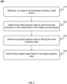
- FIG. 4 is a flowchart illustrating an exemplary process for metal artifacts correction according to some embodiments of the present disclosure.
- a process 400 may be executed by the medical system 100 (e.g., the imaging device 110, the processing device 120, or the terminal device 130 in the medical system 100), the computing device 200, or the metal artifacts correction system 300.
- the process 400 may be implemented as instructions and stored in a memory.
- the memory may be an external memory of the storage device 140 or the medical system 100, and may be accessed by the processing device 120 or the medical system 100.
- the processing device 120 or the metal artifacts correction system 300 may execute instructions, and when executing the instructions, the process 400 may be performed.
- the diagram of operations of the process 400 presented below is illustrative. In some embodiments, the process may be accomplished by utilizing one or more undescribed additional operations and/or one or more undescribed operations. In addition, an operation sequence of process 400 shown in FIG. 4 and described below is non-restrictive.
- an image to be processed including a metal portion may be obtained.
- the operation 410 may be executed by the processing device 120 or the obtaining module 310.
- the image to be processed refers to an initial scanning image that has not been processed and includes data of the metal portion, such as an image obtained by scanning an object through the imaging device 110.
- rays from a ray source may be delivered to the object through a ray filter, and the rays passing through the object may be detected as electrical signals by a detector.
- An output signal of the detector may be collected, amplified, and converted into a digital signal for each detector channel to generate projection data.
- the rays e.g., X-rays, ⁇ -rays, ⁇ -rays
- a proportion of the rays absorbed by metals may be relatively large, and the detector may receive few rays.
- a patient when performing X-ray imaging on the object, a patient may carry metal implants (e.g., metal dentures, bone nails, etc.) inside the human body, corresponding data at the metal site may be not collected or only a part of data may be collected or the intensity of the collected data of the metal is relatively weak, due to an absorption of most of the rays by the metal implants, resulting in insufficient data collection for the obtained projection data, thus forming metal artifacts in the reconstructed image.
- the metal portion may be in shown as metal artifact in the image to the processed, that is, the image to be processed may include metal artifact caused by metal (e.g., the metal implant).
- FIG. 5(a) is a schematic diagram illustrating an exemplary projection data image including a metal portion according to some embodiments of the present disclosure
- FIG. 5(b) is a schematic diagram illustrating an exemplary reconstructed image including a metal portion according to some embodiments of the present disclosure.
- the read projection value may differ significantly from the true value, resulting in a formation of metal artifacts in the image.
- the metal portion may typically appear as a blank band without actual information on the sinogram (i.e., a projection data image), i.e., missing data.
- the metal portion may generally appear as a severe stripe in the reconstructed image.
- the image to be processed may include X-ray imaging images including the metal portion. In some embodiments, the image to be processed may include X-ray images and/or CT images including the metal portion.
- the image to be processed may include a projected data image (e.g., an image shown in FIG. 5(a) ) and/or a reconstructed image (e.g., an image shown in FIG. 5(b) .
- a projected data image e.g., an image shown in FIG. 5(a)
- a reconstructed image e.g., an image shown in FIG. 5(b) .
- the processing device may obtain the image to be processed including the metal portion from the imaging device 110 and/or the storage device 140.
- the processing device 120 may obtain the corresponding image to be processed from the storage device 140 based on personal information of the object.
- the processing device 120 may obtain the image to be processed from the imaging device 110 directly.
- initial projection data may be determined by performing data restoration on the metal portion of the image to be processed.
- the operation 420 may be executed by the processing device 120 or the data restoration module 320.
- the metal portion refers to data corresponding to a metal implant, which may be shown as metal artifacts in the reconstructed image (i.e., the image to be processed) and may be shown as trajectory (also referred to as metal trajectory) (e.g., as shown in FIG. 15(b) ) in projection data (e.g., projection data determined based on a metal image as shown in process 1400).
- the data restoration refers to a process of restoring data corresponding to the metal portion.
- the data restoration may include restoring uncollected data of the metal, and/or restoring a projection value of the collected data of the metal (e.g., estimate a true projection value of the collected data of the metal), or the like.
- the initial projection data refers to the projection data obtained through the data restoration.
- the initial projection data may include restored projection data corresponding to a metal portion and collected projection data of other portions, e.g., the initial projection data may include complete projection data.
- the initial projection data may include the restored projection data corresponding to the metal portion.
- the processing device may obtain the initial projection data by performing the data restoration on the metal portion of the image to be processed.
- the data restoration process may include an interpolation process.
- the interpolation process may achieve the data restoration by interpolating a region where the metal portion is located.
- the processing device 120 may fit data corresponding to the metal portion based on the collected data at an edge of the metal portion in the sinogram, thereby achieving data recovery and obtaining the projection data corresponding to the metal portion.
- the processing device 120 may fit the data corresponding to the metal portion based on the collected data at an edge of the metal trajectory in the sinogram, and obtain complete projection data including the projection data corresponding to the metal portion and the collected projection data of other portions.
- the processing device may determine the initial projection data by using a trained data restoration model.
- the processing device 120 may input an image to be processed including the metal portion into the data restoration model, the data restoration model may output corresponding initial projection data by analyzing and processing the image to be processed.
- an output of the data restoration model may be complete projection data of the object, and the output of the data restoration model may include the restored projection data corresponding to the metal portion and the collected projection data of other portions.
- the output of the data restoration model may be the restored projection data corresponding to the metal portion.
- the data restoration model may include a machine learning model.
- the machine learning model can include a convolutional neural network (CNN), a fully connected neural network, a recurrent neural network (RNN), or the like.
- CNN convolutional neural network
- RNN recurrent neural network
- the data restoration model may be obtained by training an initial machine learning model based on first sample data.
- the first sample data may include multiple sets of samples composed of sample metal portion images and sample restoration projection data.
- the processing device may train the initial machine learning model to obtain a trained data restoration model by using sample metal portion images as training inputs of the model and corresponding sample restoration projection data as training outputs of the model.
- the accuracy of the model can be improved by establishing a loss function, or the like.
- the processing device may train the data restoration model by training in any reasonable and feasible way, which may not be limited herein.
- the processing device may obtain object information of the object corresponding to the image to be processed and determine a target restoration process based on the object information. Further, the processing device may obtain the initial projection data by performing data restoration on the metal portion of the image to be processed based on the target restoration process. More descriptions of determining the target restoration process may be found in FIG. 12 and related descriptions.
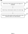
- the processing device may determine a metal image based on the image to be processed and determine a metal trajectory based on the metal image. Further, the processing device may obtain the initial projection data by performing the data restoration on the metal trajectory by using the data restoration process (e.g., the target restoration process).
- the metal trajectory may include a metal trajectory sinogram. More descriptions may be found in FIG. 14 and related descriptions.
- target projection data may be determined by filtering the initial projection data.
- the operation 430 may be executed by the processing device 120 or the filtering module 330.
- the data restoration refers to a process of inferring restored data based on reference data, and the restored data may depend on the reference data.
- the reference data may include collected data and/or restored data.
- the reference data since the reference data includes data from different frequency bands, it is inevitable to introduce some high frequency data during the data restoration process.
- some high frequency data may be introduced into the restored data (e.g., the initial projection data).
- the high frequency data refers to data where the pixel or frequency value is greater than a standard value of a corresponding portion (e.g., a portion that wears metal devices). As shown in FIG. 6(a) , high frequency data may appear as varying striped artifacts in the reconstructed image.
- the processing device may obtain the target projection data that filters out high frequency data by filtering the initial projection data.
- the processing device may obtain the target projection data by performing low-pass filtering on the initial projection data.
- the metal artifacts can be eliminated while filtering out the high frequency data introduced during the data restoration process, thereby avoiding high frequency artifacts when obtaining the reconstructed image based on the restored projection data, and improving the image quality of the reconstructed image.
- the processing device may obtain the target projection data by performing the low-pass filtering on the initial projection data directly.
- the processing device may obtain restoration data corresponding to the metal portion in the initial projection data. Further, the processing device may obtain the target projection data by performing the low-pass filtering on the restoration data corresponding to the metal portion. In some embodiments, the processing device may obtain the target projection data by performing the low-pass filtering on the restoration data corresponding to the metal portion while retaining the original projection data of other portion.
- FIG. 7 is a schematic diagram illustrating an exemplary process of filtering projection data according to some embodiments of the present disclosure, the following may be described in detail combined with FIG. 7 .
- the processing device may divide the initial projection data 710 into a first data portion 725 and a second data portion 727.
- the first data portion 725 may be raw data, i.e., the collected projection data at other portion other than the collected projection data at the metal.
- the second data portion 727 may be restoration data obtained through the data restoration, i.e., the restoration data corresponding to the metal portion.
- the processing device may determine the second data portion 727 in the initial projection data 710 by using a template.
- the template may be determined based on the collected projection data at other portion.
- the collected projection data at other portion may be determined as a template.
- the metal trajectory sinogram may be determined through threshold segmentation and other processes, and the metal trajectory sinogram may be determined as a template.
- the processing device may obtain filtered data 740 by performing the low-pass filtering on the second data portion 727.
- the processing device 120 may obtain the filtered data 740 by performing the low-pass filtering on the second data portion 727 by using Gaussian low-pass filtering.
- the processing device 120 may obtain the filtered data 740 by performing the low-pass filtering on the second data portion 727 by using a trained filtering model.
- the processing device may obtain the target projection data 750 based on the filtered data 740 and the first data portion 725 of the initial projection data 710. In some embodiments, the processing device may retain original data corresponding to the first data portion 725 (the collected projection data at other portion), and obtain filtered restored projection data 450 based on the filtered data 740 and the original data corresponding to the first data portion 725. In some embodiments, the processing device may obtain the target projection data 750 by fusing the filtered data 740 with the original data corresponding to the first data portion 725 (e.g., through an overlay fusion process).
- the remaining data may be not filtered, which can avoid affecting the image quality corresponding to the remaining data.
- the processing device may obtain a target filter and determine the target projection data by filtering the initial projection data using the target filter. In some embodiments, the processing device may determine the target filter based on at least one of the initial projection data, object information of the object corresponding to the image to be processed, and data restoration process corresponding to the initial projection data.
- the object information may include at least one of personal information, a scanning position, a scanning parameter, and historical scanning data.
- the personal information may include information such as age, gender, occupation, height, weight, fat ratio, water fat ratio, and historical cases of the object.
- the historical scanning data may include information such as a historical scanning position, a historical scanning parameter, historical reconstructed images, historical projection data of the object, or the like.
- the processing device may determine the target filter using the trained model based on the initial projection data, the object information, or the data restoration process. For example, the processing device 120 may use the trained first model to determine the target filter based on the initial projection data. For example, the processing device 120 may determine the target filter based on the initial projection data by using the trained first model. As another example, the processing device 120 may determine the target filter based on the object information by using the trained second model. As a further example, the processing device 120 may determine the target filter based on the data restoration process corresponding to the initial projection data by using a trained third model. In some embodiments, the first model, the second model, and the third model may be trained simultaneously or separately. More descriptions may be found in FIG. 8-FIG. 10 and related descriptions.
- the processing device may determine the target filter based on at least two of the initial projection data, the object information, and the data restoration process by using a filter determination model. For example, the processing device 120 may input the initial projection data and object information into the first model and the second model respectively, and the first model and the second model may output a corresponding target filter by analyzing and processing the initial projection data and object information respectively. In some embodiments, the processing device may select any one of the target filters output from the first model and the second model as a final target filter. In some embodiments, the processing device may select a target filter corresponding to information with a relatively high confidence level based on a confidence level of the initial projection data and the object information.
- the processing device may determine a final target filter based on a using frequency and a reliability of the target filter output from the first model and the second model.
- the using frequency of a target filter may reflect a count of times the target filter is used for low-pass filtering in clinical applications. For example, the count of times each filter is used for the low-pass filtering over a period of time may be counted to determine a using frequency of the target filter.
- the reliability of a target filter may reflect a quality of a result obtained when the target filter is used for the low-pass filtering. For example, a quality of a corresponding reconstructed image obtained by performing the low-pass filtering using each filter may be scored. The higher the score of the reconstructed image, the higher the reliability of the corresponding filter.
- the processing device 120 may input the initial projection data and the data restoration process (e.g., a process, types of values, a quantity of reference data, and a location and/or type for performing the data restoration on the metal portion on the metal portion) into a filter determination model, and the filter determination model may output a target filter by analyzing and processing the initial projection data and the data restoration process.
- the data restoration process e.g., a process, types of values, a quantity of reference data, and a location and/or type for performing the data restoration on the metal portion on the metal portion
- the processing device 120 may input the initial projection data, the object information, and the data restoration process (e.g., a process, types of values, a quantity of reference data, and a location and/or type for performing the data restoration on the metal portion on the metal portion) into the filter determination model, the filter determination module may output a target filter by analyzing and processing the initial projection data, the object information, and the data restoration process.
- the data restoration process e.g., a process, types of values, a quantity of reference data, and a location and/or type for performing the data restoration on the metal portion on the metal portion
- the filter determination model may be obtained by training the initial machine learning model using second sample data.
- the second sample data may include multiple sets of sample data corresponding to multiple different objects, each set of sample data may be composed of at least two of sample initial projection data, sample object information, and sample data restoration process, and a corresponding sample target filter.
- the processing device 120 may obtain a trained filter determination model by training the initial machine learning model using the initial projection data, the sample object information, and the sample data restoration process of the object as training inputs and the sample target filter as a training output.
- the processing device may determine the sample target filter by evaluating the sample target projection data obtained by different filters. For example, the processing device 120 may score a smoothness and/or granularity of the sample target projection data (or an reconstructed image corresponding to the sample target projection data) obtained by each filter, and determine a filter corresponding to sample target projection data (or an reconstructed image corresponding to the sample target projection data) with a highest comprehensive score as a sample target filter.
- the smoothness reflects a degree of brightness change in different regions of the image (e.g., sample target projection data image or a reconstructed image corresponding to the sample target projection data). The smoother the brightness change, the higher the image quality.
- the granularity reflects a thickness of a density region (i.e., particles) of the image (e.g., sample target projection data image or a reconstructed image corresponding to the sample target projection data). The finer the granularity, the higher the clarity of the image.
- the processing device 120 may score quality of the reconstructed image corresponding to the sample target projection data obtained by each filter, and determine a filter corresponding to a reconstructed image with a highest score as a sample target filter. In some embodiments, a score of the sample target projection data obtained by each filter may also be determined by the user.
- the processing device may obtain the target projection data by filtering out data higher than a target frequency band from the initial projection data. In some embodiments, the processing device may determine the target frequency based on an average value, a maximum value, and other projection data corresponding to the metal portion obtained from multiple sets of clinical scanning data. In some embodiments, the target frequency may be flexibly set by the user based on actual needs.
- the processing device may determine a target frequency band based on at least one of the object information corresponding to the image to be processed, the data restoration process corresponding to the initial projection data, and the initial projection data. More descriptions may be found in FIG. 11 and related descriptions.
- the processing device may obtain the target projection data by filtering out data higher than the target frequency band from the initial projection data using the target filter.
- a target image may be determined based on the target projection data.
- the operation 440 may be executed by the processing device 120 or the image generation module 340.
- the processing device may obtain a target image that filters out high frequency artifacts and/or metal artifacts through back-projection reconstruction based on the target projection data.
- the processing device may reconstruct the target projection data through a back-projection reconstruction algorithm to obtain an intermediate reconstructed image. Further, the processing device may obtain the target image based on the intermediate reconstructed image and a segmented metal image.
- the processing device may obtain the target image by fusing the intermediate reconstructed image with the metal image. For example, the processing device 120 may obtain the target image by superimposing the metal image onto the intermediate reconstructed image.
- the back-projection reconstruction algorithm may include but are not limited to parallel ray beam filtered back-projection reconstruction and/or fan-shaped ray beam back-projection reconstruction.
- the target image may be obtained through other image reconstruction processes, such as analytical reconstruction, planar reconstruction, maximum density projection, volume roaming technology VRT, or the like, which may not be limited herein.
- FIG. 6 is a schematic diagram illustrating exemplary images before and after correction according to some embodiments of the present disclosure
- an image shown in FIG. 6(a) may be a reconstructed image without filtering (i.e., a reconstructed image obtained directly from the restored projection data), while an image shown in FIG. 6(b) may be the target image (i.e., the filtered reconstructed image).
- FIG. 6(a) may be a reconstructed image without filtering (i.e., a reconstructed image obtained directly from the restored projection data)
- an image shown in FIG. 6(b) may be the target image (i.e., the filtered reconstructed image).
- the reconstructed image obtained directly from the restored projection data may include some small fine grained artifacts, i.e., the high frequency artifacts.
- the small fine grained artifacts in the target image shown in FIG. 6(b) may be weakened.
- FIG. 8 is a schematic diagram illustrating an exemplary process of determining a target filter according to some embodiments of the present disclosure.
- the process 800 may be executed by the medical system 100 (e.g., the processing device 120 in the medical system 100), the computing device 200, or the metal artifacts correction system 300.
- the process 800 may be implemented as instructions and stored in a memory.
- the memory may be external to the storage device 140 or the medical system 100, and may be accessed by the processing device 120 or the medical system 100.
- the processing device 120 or the metal artifacts correction system 300 may execute the instructions, and when executing the instructions, the process 800 may be performed.
- the diagram of operations of the process 800 presented below is illustrative. In some embodiments, the process may be accomplished by utilizing one or more undescribed additional operations and/or one or more undescribed operations. In addition, the operation sequence of the process 800 shown in FIG. 8 and described below is non-restrictive.
- the processing device may obtain initial projection data corresponding to the image to be processed. As described above, the processing device may determine the initial projection data by performing the data restoration on the metal portion of the image to be processed. More descriptions may be found in FIG. 4 and related descriptions, which may not be repeated herein.
- the processing device may determine the target filter based on the initial projection data using a trained first model.
- the first model may include a machine learning model, such as CNN, full connected neural network, RNN, or the like.
- the first model may output a corresponding target filter by analyzing and processing the initial projection data. For example, the first model may determine a corresponding target filter and output the corresponding target filter by analyzing the scanning position in the initial projection data, data values of all data (e.g., pixel values or frequency values) and other information.
- data values of all data e.g., pixel values or frequency values
- the first model may be obtained by training based on first training samples.
- the first model may be obtained by training the initial machine learning model based on the one or more first training samples.
- each first training sample may include sample initial projection data and a corresponding first sample target filter.
- the multiple first training samples may include one or more scanning positions and/or one or more lesion types.
- the sample initial projection data corresponding to the scanning position and the corresponding first sample target filter may form a first training sample.
- the processing device 120 may obtain sample data from multiple different scanning positions such as head, neck, chest, stomach, arms, legs, feet, or the like.
- the multiple first training samples may correspond to one or more sample objects.
- the first sample target filter corresponding to the initial projection data of the sample may be determined by evaluating the sample target projection data. In some embodiments, the first sample target filter corresponding to the sample initial projection data may be determined by evaluating the sample target projection data. For example, for the same set of initial projection data, the processing device 120 may score the smoothness and/or granularity of the sample target projection data obtained through different filters, and/or score the quality of the reconstructed image corresponding to the sample target projection data. Further, the processing device 120 may determine the first sample target filter based on the score. In some embodiments, the processing device may determine a highest score as a first sample target filter. As another example, for the same set of initial projection data, the user may score the quality of sample target projection data obtained by different filters or label the first sample target filter corresponding to the initial projection data based on the data quality directly.
- the processing device may train a first initial model to obtain the trained first model by using the sample initial projection data of the one or more first training samples as inputs of the model training and the first sample target filter as an output of the model training.
- the processing device may obtain the first model trained by training in any reasonable and feasible way, which may not be limited herein.
- the processing device may determine the target projection data by filtering the initial projection data using the target filter output from the first model. More descriptions may be found in FIG. 4 and related descriptions, which may not be repeated herein.
- FIG. 9 is a schematic diagram illustrating an exemplary process of determining a target filter according to other embodiments of the present disclosure.
- the process 900 may be executed by the medical system 100 (e.g., the processing device 120 in the medical system 100), the computing device 200, or the metal artifacts correction system 300.
- the process 900 may be implemented as instructions (e.g., applications) and stored in a memory, such as the external storage device 140 or the medical system 100 which may be accessed by the processing device 120 or the medical system 100.
- the processing device 120 or the metal artifacts correction system 300 may execute instructions, and when executing the instructions, the process 900 may be performed.
- the diagram of operations of the process 900 presented below is illustrative. In some embodiments, the process may be accomplished by utilizing one or more undescribed additional operations and/or one or more undescribed operations. In addition, the operation sequence of the process 900 shown in FIG. 9 and described below is non-restrictive.
- the processing device may obtain object information of the object corresponding to the image to be processed.
- the object information may include at least one of personal information (e.g., gender, age, medical history, etc.), a scanning position of the object (e.g., patents), a scanning parameter (e.g., tube current, tube voltage, scanning time, the position of the tube, the position of the detector, the scanning angle, etc.), or historical scanning data.
- the processing device may obtain the object information from an imaging device (e.g., the imaging device 110) or a storage device (e.g., the storage device 140).
- the processing device may obtain the object information from the terminal device.
- the processing device 120 may obtain the object information input by the user from the terminal device 130.
- the processing device can obtain the object information by scanning a two-dimensional code of the object.
- the processing device 120 may obtain the object information by scanning the two-dimensional code of the object.
- the processing device 120 may obtain the object information by scanning the two-dimensional code of human body and a bed of the object.
- the processing device may input the object information into a trained second model.
- the second model may include a machine learning model, such as CNN, full connected neural network, RNN, or the like.
- the second model may output the corresponding target filter by analyzing and processing the object information.
- the second model may determine the corresponding target filter and output the target filter by analyzing the scanning position, the age, the gender, the medical history, and other information in the object information.
- the second model may be obtained by training based on the second training samples.
- the second model may be obtained by training the initial machine learning model based on the one or more second training samples.
- each second training sample may include sample object information and a corresponding second sample target filter.
- the multiple second training samples may include one or more scanning objects and/or one or more lesion types.
- sample object information corresponding to a lesion type and the second sample target filter may form a second training sample, and the processing device 120 may obtain sample data of brain tumors, thyroid, breast cancer, fractures, and other different focus types.
- the processing device may determine a second sample target filter corresponding to the sample object information through statistical analysis.
- the processing device 120 may perform the statistical analysis on scanning values (e.g., CT values, scanning image pixel values, and projection data values) of various tissues or organs of different types of sample objects, obtain a standard value of projection data for each organization or organ, and determine a corresponding second sample target filter based on the standard values.
- scanning values e.g., CT values, scanning image pixel values, and projection data values
- the processing device may train the second initial model to obtain a trained second model by using the sample object information of the one or more second training samples as inputs of the model training and the second sample target filter as an output of the model training.
- the processing device may obtain the second model by training in any reasonable and feasible way, which may not be limited herein.
- the processing device may determine the target projection data by filtering the initial projection data using the target filter output from the second model. More descriptions may be found in FIG. 4 and related descriptions, which may not be repeated herein.
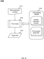
- FIG. 10 is a schematic diagram illustrating an exemplary process of determining a target filter according to other embodiments of the present disclosure.
- the process 1000 may be executed by the medical system 100 (e.g., the processing device 120 in the medical system 100), the computing device 200, or the metal artifacts correction system 300.
- the process 1000 may be implemented as instructions (e.g., applications) and stored in a memory, such as the storage device 140 or the medical system 100, which may be accessed by the processing device 120 or the medical system 100.
- the processing device 120 or the metal artifacts correction system 300 may execute instructions, and when executing the instructions, the process 1000 may be performed.
- the diagram of operations of the process 1000 presented below is illustrative. In some embodiments, the process may be accomplished by utilizing one or more undescribed additional operations and/or one or more undescribed operations. In addition, the operation sequence of the process 1000 shown in FIG. 10 and described below is non-restrictive.
- the processing device may obtain a data restoration process corresponding to the initial projection data.
- the data restoration process may be related to parameters used for performing the data restoration on the metal portion.
- the data restoration process may include manners used for performing the data restoration (e.g., an interpolation manner, a smoothing manner, a manner by using a data restoration model, etc.), types of values used during the data restoration (e.g., detector coordinate values, pixel values, etc.), a quantity of the reference data, a position of the reference data, and/or a type of reference data, or the like.
- the processing device may input the data restoration process into a trained third model.
- the processing device may input the manners used for performing the data restoration, the types of values used during the data restoration, the quantity of the reference data, the position of the reference data, and/or the type of reference data into the third model.
- the third model may include a machine learning model, such as CNN, fully connected neural network, RNN, or the like.
- the third model may output a corresponding target filter by analyzing and processing the data restoration process.
- the third model may output the corresponding target filter by analyzing manners used for the data restoration, types of values used in the data restoration process, a count of the reference data, a position of the reference data, and/or types of reference data, or the like.
- the third model may be obtained by training based on third training samples.
- the third model may be obtained by training the initial machine learning model based on the one or more third training samples.
- each third training sample may include a sample restoration process and a corresponding third sample target filter.
- the multiple third training samples may include one or more scanning positions and/or one or more lesion types.
- the sample restoration process corresponding to the scanning position and the corresponding third sample target filter may form a third training sample.
- the processing device 120 may obtain sample data from multiple different scanning regions such as head, neck, chest, stomach, arms, legs, feet, or the like.
- the multiple third training samples may correspond to one or more sample objects.
- the third sample target filter corresponding to the sample restoration process may be determined by evaluating the initial projection data of the sample and/or the target projection data. For example, for the same set of initial projection data, the processing device 120 may score a smoothness and/or granularity of the sample target projection data obtained through different filters, and/or score quality of the reconstructed image corresponding to the sample target projection data, and determine the third sample target filter based on the score. As another example, for the same set of initial projection data, the user may label a corresponding third sample target filter based on data frequency values of the initial projection data obtained by different sample restoration processes.
- the processing device may train the third initial model to obtain a trained third model by using the sample restoration processes of the one or more third training samples as inputs of the model training and the third sample target filter as an output of the model training.
- the processing device may obtain the third model by training in any reasonable and feasible way, which may not be limited herein.
- the processing device may determine the target projection data by filtering the initial projection data using the target filter output from the third model. More descriptions may be found in FIG. 4 and related descriptions, which may not be repeated herein.
- FIG. 11 is a schematic diagram illustrating an exemplary process of determining a target frequency band according to some embodiments of the present disclosure.
- the process 1100 may be executed by the medical system 100 (e.g., the processing device 120 in the medical system 100), the computing device 200, or the metal artifacts correction system 300.
- the process 1100 may be implemented as instructions (e.g., applications) and stored in a memory, such as the storage device 140 or the medical system 100, which may be accessed by the processing device 120 or the medical system 100.
- the processing device 120 or the metal artifacts correction system 300 may execute instructions, and when executing the instructions, the process 1100 may be performed.
- the diagram of operations of the process 1100 presented below is illustrative. In some embodiments, the process may be accomplished by utilizing one or more undescribed additional operations and/or one or more undescribed operations. In addition, the operation sequence of the process 1100 shown in FIG. 11 and described below is non-restrictive.
- a target frequency band may be determined based on at least one of object information of an object corresponding to the image to be processed, a data restoration process corresponding to the initial projection data, or the initial projection data.
- different types of the object information may correspond to different target frequencies.
- objects of different age groups e.g., infants, students, youth, middle-aged persons, and elderly persons
- the different target frequencies e.g., a target frequency of youth being higher than a target frequency of the elderly and middle-aged person
- objects of different body types e.g., thin and weak population or obese population
- target frequencies e.g., a target frequency of the obese population being higher than a target frequency of the thin and weak population
- objects of different scanning positions may correspond to different target frequencies.
- the target frequencies corresponding to different types of object information may be obtained by the user or the processing device through a large amount of historical data (e.g., scanning data corresponding to multiple sets of different object information).
- the processing device may input at least one of the object information corresponding to the image to be processed, the data restoration process corresponding to the initial projection data, and the initial projection data into a trained frequency band determination model.
- the frequency band determination model may output a corresponding target frequency through analysis and processing.
- the frequency band determination model may include one or more sub-models.
- the sub-model may analyze and process the input two or more types of data and output a corresponding target frequency.
- the frequency band determination model includes two sub-models
- the one of the two sub-models may analyze and process the input object information
- the other sub-model may analyze and process the input data restoration process and the initial projection data.
- the frequency band determination model includes three sub-models
- the three sub-models may analyze and process the input object information, the data restoration process, and the initial projection data, respectively.
- the target frequency may be determined based on a preset weight value.
- the frequency band determination model when the frequency band determination model includes multiple sub-models, the frequency band determination model may be obtained through joint training.
- the processing device 120 may obtain the frequency band determination model by training the initial machine learning model based on third sample data.
- the third sample data may include two or more types of data corresponding to the input data, including sample object information, sample restoration process, and sample initial projection data.
- the frequency band determination model may include the machine learning model, such as CNN, fully connected neural network, RNN, or the like.
- the target projection data may be obtained by filtering out data higher than the target frequency band from the initial projection data. More descriptions may be found in FIG. 4 and related descriptions, which may not be repeated herein.
- FIG. 12 is a schematic diagram illustrating an exemplary process of determining a target restoring process according to some embodiments of the present disclosure.
- the process 1200 may be executed by the medical system 100 (e.g., the processing device 120 in the medical system 100), the computing device 200, or the metal artifacts correction system 300.
- the process 1200 may be implemented as instructions (e.g., applications) and stored in a memory, such as the storage device 140 or the medical system 100, which may be accessed by the processing device 120 or the medical system 100.
- the processing device 120 or the metal artifacts correction system 300 may execute the instructions, and when executing the instructions, the process 1200 may be performed.
- the diagram of operations of the process 1200 presented below is illustrative. In some embodiments, the process may be accomplished by utilizing one or more undescribed additional operations and/or one or more undescribed operations. In addition, the operation sequence of the process 1200 shown in FIG. 12 and described below is non-restrictive.
- the processing device may obtain object information of the object corresponding to the image to be processed.
- the object information may include at least one of personal information, a scanning position, a scanning parameter, or historical scanning data. More descriptions may be found in FIG. 4 and related descriptions, which may not be repeated herein.
- the processing device may input the object information into a trained restoration process determination model.
- the trained restoration process determination model may include the machine learning model, such as CNN, fully connected neural network, RNN, or the like.
- the restoration process determination model may output a corresponding target restoration process by analyzing and processing the object information.
- the target restoration process may include manners used for the data restoration (e.g., an interpolation manner, a smoothing manner, a manner by using a data restoration model, etc.), a count of reference data used in the restoration process, a position/type of reference data used in the restoration process, or any combination thereof.
- the restoration process determination model may determine a corresponding target restoration process and output the target restoration process by analyzing personal information such as age, gender, weight, height, a scanning position, a scanning parameter, and historical scanning data in the object information.
- the processing device may obtain the initial projection data by performing the data restoration on the metal portion of the image to be processed based on the target restoration process.
- the restoration process determination model may be trained based on fourth sample data.
- the fourth sample data may include sample object information of different sample objects and a reference data restoration process corresponding to the sample object information as shown in the operation 1240.
- the fourth sample data may include one or more scanning positions and/or one or more lesion types.
- the processing device may obtain at least one candidate data restoration process. For each candidate data restoration process, the processing device may determine a score of the sample initial projection data and/or sample target projection data corresponding to the candidate data restoration process. For example, the processing device 120 may rate a smoothness and/or granularity of the sample initial projection data or quality of the reconstructed image corresponding to the sample initial projection data. As another example, the processing device 120 may rate a smoothness of the sample target projection data or the quality of the reconstructed image corresponding to the sample target projection data. In some embodiments, the rating may be automatically determined by the system or determined by the user.
- the processing device may determine the reference data restoration process of the sample object based on the score of the sample target projection data and sample initial projection data corresponding to the candidate data restoration process. For example, the processing device 120 may select a candidate data restoration process corresponding to sample initial projection data with a highest score and determine the selected candidate data restoration process as a reference data restoration process. As another example, the processing device 120 may select a candidate data restoration process corresponding to sample target projection data with a highest score, and determine the selected candidate data restoration process as a reference data restoration process.
- the processing device 120 may determine a weighted value corresponding to the candidate data restoration process based on the score of the sample initial projection data and the sample target projection data, select a candidate data restoration process with a highest weighted value, and determine the selected candidate data restoration process as a reference data restoration process.
- the processing device may train the initial model to obtain a trained restoration process determination module by using the sample object information of the fourth sample data as an input of the model training and the reference data restoration process as an output of the model training.
- the processing device may obtain the restoration process determination module may be obtained by training in any reasonable and feasible way, which may not be limited herein.
- FIG. 14 is a schematic diagram illustrating an exemplary process of determining data restoration according to some embodiments of the present disclosure.
- the process 1400 may be executed by the medical system 100 (e.g., the processing device 120 in the medical system 100), the computing device 200, or the metal artifacts correction system 300.
- the process 1400 may be implemented as instructions (e.g., applications) and stored in a memory, such as the storage device 140 or the medical system 100, which may be accessed by the processing device 120 or the medical system 100.
- the processing device 120 or the metal artifacts correction system 300 may execute the instructions, and when executing the instructions, the process 1400 may be performed.
- the diagram of operations of the process 1400 presented below is illustrative. In some embodiments, the process may be accomplished by utilizing one or more undescribed additional operations and/or one or more undescribed operations. In addition, the operation sequence of the process 1400 shown in FIG. 14 and described below is non-restrictive.
- a metal image may be determined based on the image to be processed.
- the metal image refers to a reconstructed image of a corresponding metal portion within the target object, such as the image shown in FIG. 15(a) .
- the processing device may extract the metal image from the image to be processed through a threshold process. For example, in an CT imaging, there are significant differences in CT values between different tissues. A CT value for air may be -1000HU, a CT value for fat may be -120-90HU, a CT value of bone may be 300-2000HU, and CT values for various metals may be much greater than 2000HU, even tens of thousands.
- the processing device 120 may determine a corresponding metal image (e.g., an image shown in FIG.
- the processing device 120 may set a pixel threshold based on pixel values of different tissues in the reconstructed image and segment the metal image from the reconstructed image based on the pixel threshold.
- the processing device may extract the metal image from the image to be processed using the trained machine learning model (e.g., a U-net model). For example, the processing device 120 may input the image to be processed into a trained U-net model, and the U-net model may output a corresponding metal image through analysis and processing.
- the trained machine learning model e.g., a U-net model
- the processing device may preprocess the image to be processed and determine the metal image based on the preprocessed image.
- the preprocessing may include but is not limited to noise reduction, bilateral filtering, or the like.
- a metal trajectory may be determined based on the metal image.
- the metal trajectory may include a metal trajectory sinogram.
- the projection data of the target object may be in a form of a sinogram, as shown in FIG. 15(c) .
- the metal trajectory sinogram refers to projection data corresponding to the metal portion, such as an image shown in FIG. 15(b) .
- the processing device may determine the metal trajectory sinogram based on the metal image using an orthographic projection process.
- the processing device may determine the metal trajectory sinogram based on the original projection data directly.
- the processing device 120 may determine the metal trajectory sinogram based on the projection data shown in FIG. 5(a) through processes such as threshold segmentation.
- the processing device 120 may input the image to be processed into a trained segmentation model; the segmentation model may output a corresponding metal trajectory sinogram directly through analysis and processing.
- the initial projection data may be obtained by performing the data restoration based on the metal trajectory.
- the processing device may determine projection data of a metal neighborhood region based on the metal trajectory sinogram; the initial projection data may be obtained by performing the data restoration based on the projection data of the metal neighborhood region.
- the metal neighborhood region refers to a region that is different from and adjacent to a region corresponding to the metal (e.g., a region adjacent to an edge of the metal trajectory in a certain range).
- the metal neighborhood region may be a region within 1 mm, 2 mm, or 3 mm outside an edge of the trajectory 510.
- the processing device 120 may calculate data values in a metal region based on the data values in the metal neighborhood region, thereby obtaining the initial projection data.
- the processing device may determine the projection data of the metal neighborhood region based on the metal trajectory sinogram by using a target restoration process (e.g., the target restoration process determined through the process 1200); the initial projection data may be obtained by performing the data restoration based on the projection data of the metal neighborhood region.
- a target restoration process e.g., the target restoration process determined through the process 1200
- the processing device may determine the projection data corresponding to the metal portion through an interpolation process.
- the processing device may obtain the initial projection data by performing the data restoration based on the metal trajectory sinogram and the reference image. For example, the processing device 120 may fill a metal region segmented in the reconstructed image with CT values of soft tissues; the reconstructed images may be clustered after filling using a 3D K-means algorithm, and the human tissue may be clustered into air, fat, soft tissue, and bone; and the reference image may be obtained by assigning values to different clustered tissues. Further, the processing device 120 may obtain the initial projection data by determining the data corresponding to the metal region based on ortho projection data corresponding to the reference image and the metal portion.
- the processing device may perform high frequency data filtering during the data restoration process. For example, in the data restoration process by using the interpolation process, the processing device 120 may compare calculated restored data with a preset threshold. When the restored data is greater than the preset threshold, the processing device 120 may determine a preset standard value as the restoration data corresponding to the metal portion; otherwise, the calculated restored data may be determined as the restored data corresponding to the metal portion.
- the preset threshold may be determined by the user based on actual operating experience or automatically determined by the system through statistical analysis.
- the numbers expressing quantities or properties used to describe and claim certain embodiments of the application are to be understood as being modified in some instances by the term "about,” “approximate,” or “substantially.”
- “about,” “approximate,” or “substantially” may indicate ⁇ 1 %, ⁇ 5%, ⁇ 10%, or ⁇ 20% variation of the value it describes, unless otherwise stated.
- the numerical parameters set forth in the written description and attached claims are approximations that may vary depending upon the desired properties sought to be obtained by a particular embodiment.
- the numerical parameters should be construed in light of the number of reported significant digits and by applying ordinary rounding techniques. Notwithstanding that the numerical ranges and parameters setting forth the broad scope of some embodiments of the application are approximations, the numerical values set forth in the specific examples are reported as precisely as practicable.
Landscapes
- Engineering & Computer Science (AREA)
- Physics & Mathematics (AREA)
- General Physics & Mathematics (AREA)
- Theoretical Computer Science (AREA)
- Computer Vision & Pattern Recognition (AREA)
- Apparatus For Radiation Diagnosis (AREA)
- Image Processing (AREA)
Applications Claiming Priority (1)
| Application Number | Priority Date | Filing Date | Title |
|---|---|---|---|
| CN202211307598.XA CN115564858B (zh) | 2022-10-25 | 2022-10-25 | 一种金属伪影的校正方法、系统和x射线图像重建方法 |
Publications (1)
| Publication Number | Publication Date |
|---|---|
| EP4369302A1 true EP4369302A1 (de) | 2024-05-15 |
Family
ID=84746639
Family Applications (1)
| Application Number | Title | Priority Date | Filing Date |
|---|---|---|---|
| EP23205813.1A Pending EP4369302A1 (de) | 2022-10-25 | 2023-10-25 | Verfahren und systeme zur korrektur von metallartefakten |
Country Status (3)
| Country | Link |
|---|---|
| US (1) | US20240233214A9 (de) |
| EP (1) | EP4369302A1 (de) |
| CN (1) | CN115564858B (de) |
Families Citing this family (3)
| Publication number | Priority date | Publication date | Assignee | Title |
|---|---|---|---|---|
| CN116385582A (zh) * | 2023-03-30 | 2023-07-04 | 重庆理工大学 | 基于深度学习的x射线荧光ct自吸收校正方法 |
| CN120430994B (zh) * | 2025-06-27 | 2025-09-23 | 上海联影医疗科技股份有限公司 | 医学图像处理系统及方法 |
| KR102926116B1 (ko) * | 2025-08-12 | 2026-02-12 | (주)바르넥스이미징 | 암시적 신경 표현 기반의 컴퓨터 단층촬영 영상 금속 인공음영 제거 장치 및 방법 |
Citations (2)
| Publication number | Priority date | Publication date | Assignee | Title |
|---|---|---|---|---|
| EP2662834A1 (de) * | 2012-04-27 | 2013-11-13 | Nihon University | Bildverarbeitungsvorrichtung, Röntgen-CT-Photographiegerät und Bildverarbeitungsverfahren |
| US20210012541A1 (en) * | 2019-07-11 | 2021-01-14 | Canon Medical Systems Corporation | Apparatus and method using deep learning (dl) to improve analytical tomographic image reconstruction |
Family Cites Families (14)
| Publication number | Priority date | Publication date | Assignee | Title |
|---|---|---|---|---|
| US4729100A (en) * | 1984-08-28 | 1988-03-01 | Kabushiki Kaisha Toshiba | CT System which convolutes projection data with a frequency varying filter function |
| US7376255B2 (en) * | 2004-06-23 | 2008-05-20 | General Electric Company | System and method for image reconstruction |
| GB201112359D0 (en) * | 2011-07-19 | 2011-08-31 | Univ Antwerpen | Filter for tomographic reconstruction |
| DE102012206714A1 (de) * | 2011-08-10 | 2013-02-14 | Friedrich-Alexander-Universität Erlangen-Nürnberg | Verfahren, Recheneinheit, CT-System und C-Bogen-System zur Reduktion von Metallartefakten in CT-Bilddatensätzen |
| CN103279929B (zh) * | 2013-05-25 | 2015-11-18 | 北京工业大学 | 一种基于余弦积分的ct图像金属轨迹预测和伪影去除方法 |
| WO2014203783A1 (ja) * | 2013-06-20 | 2014-12-24 | 株式会社東芝 | X線ct装置及び医用画像診断装置 |
| CN103617598B (zh) * | 2013-11-10 | 2016-08-31 | 北京工业大学 | 一种基于轨迹的ct图像金属伪影去除方法 |
| US9483851B2 (en) * | 2014-07-14 | 2016-11-01 | General Electric Company | Systems and methods for filtering for image generation |
| CN106910165B (zh) * | 2015-12-23 | 2023-06-30 | 通用电气公司 | 修复原始ct投影数据的方法及装置、ct成像系统 |
| CN105701778B (zh) * | 2016-01-11 | 2018-04-20 | 赛诺威盛科技(北京)有限公司 | 一种从ct图像中去除金属伪影的方法 |
| US11176428B2 (en) * | 2019-04-01 | 2021-11-16 | Canon Medical Systems Corporation | Apparatus and method for sinogram restoration in computed tomography (CT) using adaptive filtering with deep learning (DL) |
| CN111815521B (zh) * | 2020-05-27 | 2024-02-13 | 南京国科精准医学科技有限公司 | 一种基于先验图像的锥束ct金属伪影校正算法 |
| KR102414094B1 (ko) * | 2020-08-18 | 2022-06-27 | 연세대학교 산학협력단 | Ct영상의 금속 아티팩트 보정 방법 및 장치 |
| CN113781595B (zh) * | 2021-08-26 | 2024-03-08 | 深圳市菲森科技有限公司 | 一种口腔锥形束ct图像的金属伪影去除方法和系统 |
-
2022
- 2022-10-25 CN CN202211307598.XA patent/CN115564858B/zh active Active
-
2023
- 2023-10-25 US US18/494,737 patent/US20240233214A9/en active Pending
- 2023-10-25 EP EP23205813.1A patent/EP4369302A1/de active Pending
Patent Citations (2)
| Publication number | Priority date | Publication date | Assignee | Title |
|---|---|---|---|---|
| EP2662834A1 (de) * | 2012-04-27 | 2013-11-13 | Nihon University | Bildverarbeitungsvorrichtung, Röntgen-CT-Photographiegerät und Bildverarbeitungsverfahren |
| US20210012541A1 (en) * | 2019-07-11 | 2021-01-14 | Canon Medical Systems Corporation | Apparatus and method using deep learning (dl) to improve analytical tomographic image reconstruction |
Non-Patent Citations (3)
| Title |
|---|
| KAWASHIMA HIROKI ET AL: "Algorithm-based artifact reduction in patients with arms-down positioning in computed tomography", PHYSICA MEDICA, ACTA MEDICA EDIZIONI E CONGRESSI, ROME, IT, vol. 69, 9 December 2019 (2019-12-09), pages 61 - 69, XP085985640, ISSN: 1120-1797, [retrieved on 20191209], DOI: 10.1016/J.EJMP.2019.11.019 * |
| KYE YOUNG JEONG ET AL: "Metal artifact reduction based on sinogram correction in CT", 2009 IEEE NUCLEAR SCIENCE SYMPOSIUM AND MEDICAL IMAGING CONFERENCE (NSS/MIC 2009), ORLANDO, FL, USA, IEEE, PISCATAWAY, NJ, USA, 24 October 2009 (2009-10-24), pages 3480 - 3483, XP031826416, ISBN: 978-1-4244-3961-4 * |
| NIU TIANYE ET AL: "Quantitative cone-beam CT imaging in radiation therapy using planning CT as a prior: First patient studies", MEDICAL PHYSICS, AIP, MELVILLE, NY, US, vol. 39, no. 4, 1 April 2012 (2012-04-01), pages 1991 - 2000, XP012160951, ISSN: 0094-2405, [retrieved on 20120320], DOI: 10.1118/1.3693050 * |
Also Published As
| Publication number | Publication date |
|---|---|
| CN115564858B (zh) | 2026-03-27 |
| US20240135605A1 (en) | 2024-04-25 |
| US20240233214A9 (en) | 2024-07-11 |
| CN115564858A (zh) | 2023-01-03 |
Similar Documents
| Publication | Publication Date | Title |
|---|---|---|
| US11562469B2 (en) | System and method for image processing | |
| US10839567B2 (en) | Systems and methods for correcting mismatch induced by respiratory motion in positron emission tomography image reconstruction | |
| US20240135605A1 (en) | Methods and systems for metal artifacts correction | |
| US11399779B2 (en) | System-independent quantitative perfusion imaging | |
| US20200143521A1 (en) | System and method for image correction | |
| US8355555B2 (en) | System and method for multi-image based virtual non-contrast image enhancement for dual source CT | |
| EP3264985B1 (de) | Tomografiebildgebungsvorrichtung und verfahren zur rekonstruktion von tomografiebildern | |
| CN107545584A (zh) | 医学图像中定位感兴趣区域的方法、装置及其系统 | |
| US11995745B2 (en) | Systems and methods for correcting mismatch induced by respiratory motion in positron emission tomography image reconstruction | |
| US10032295B2 (en) | Tomography apparatus and method of processing tomography image | |
| US12396699B2 (en) | Imaging systems and methods | |
| US12211176B2 (en) | Systems and methods for image processing | |
| CN113780531B (zh) | Gan神经网络的创建方法、处理cxr胸部图像和装置 | |
| Abadi et al. | Emphysema quantifications with CT scan: assessing the effects of acquisition protocols and imaging parameters using virtual imaging trials | |
| KR20170073640A (ko) | 다중 수집을 통해 콘트라스트를 정규화하는 방법 및 시스템 | |
| US20230419455A1 (en) | System and method for image correction | |
| Mettivier et al. | The Napoli-Varna-Davis project for virtual clinical trials in X-ray breast imaging | |
| US20250166251A1 (en) | Methods and systems for correcting metal artifacts | |
| CN116342726A (zh) | 基于结构增强与伪影估计的稀疏角度ct图像伪影抑制方法 | |
| US20240312119A1 (en) | Systems and methods for image reconstruction | |
| Li et al. | Semi-supervised spatial-frequency transformer for metal artifact reduction in maxillofacial CT and evaluation with intraoral scan | |
| CN118735817B (zh) | 一种牙科cbct图像滤波去噪方法及系统 | |
| Weikang et al. | A nonuniform projection distribution CT method for solitary lung nodule follow-up: personal previous lung image-guided, patchwise, low-rank constrained imaging | |
| Passand | Quality assessment of clinical thorax CT images | |
| Visvikis | PET-CT Systems |
Legal Events
| Date | Code | Title | Description |
|---|---|---|---|
| PUAI | Public reference made under article 153(3) epc to a published international application that has entered the european phase |
Free format text: ORIGINAL CODE: 0009012 |
|
| STAA | Information on the status of an ep patent application or granted ep patent |
Free format text: STATUS: REQUEST FOR EXAMINATION WAS MADE |
|
| 17P | Request for examination filed |
Effective date: 20231025 |
|
| AK | Designated contracting states |
Kind code of ref document: A1 Designated state(s): AL AT BE BG CH CY CZ DE DK EE ES FI FR GB GR HR HU IE IS IT LI LT LU LV MC ME MK MT NL NO PL PT RO RS SE SI SK SM TR |